Principles of Flight
This page covers Task D. Principles of Flight from the FAA-S-ACS-25 Flight Instructor for Airplane Category Airman Certification Standards.
Overview
Aerodynamic theory was developed to answer important questions necessary for airplane design. For example, to calculate how much lift a wing might produce. This began with simple theories and models.
- 2D inviscid, incompressible flow can be used to calculate the lift on an airfoil of infinite span.
- Air can be considered incompressible (constant density) at speeds of approximatly 260 knots or less.
- Viscous effects were introduced to calculate drag.
- 3D flow, or for wings of finite span a spanwise velocity component exists that leads to deflection of the flow downwards and additional drag.
- It's worth keeping these different concepts separate to better understand and interpret results when presented (often incorrectly) in aviation literature.
- Viscous vs. inviscid
- Incompressible vs. compressibile
- 2D (airfoils) vs. 3D (wings)
- Static pressure + dynamic pressure = stagnation pressure (from Bernoulli's)
- Bernoulli's principle is a statement of conservation of energy, so is valid only for inviscid flows.
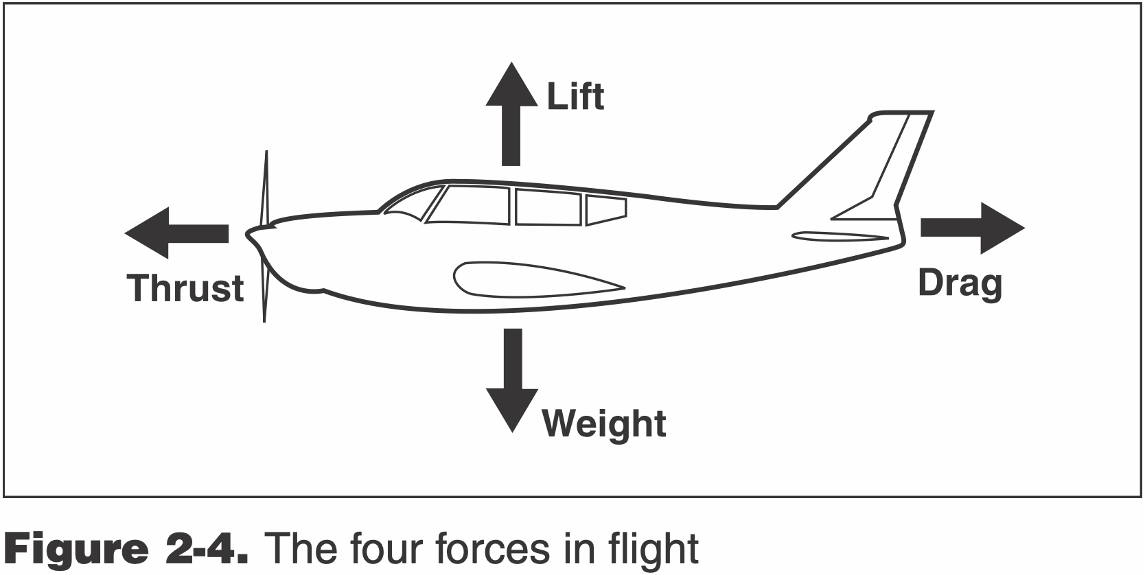
Lift
Lift is given by the following equation
Where
Angle of Attack
The angle between the chord line of the wing and the relative airflow.
For small angles of attack,
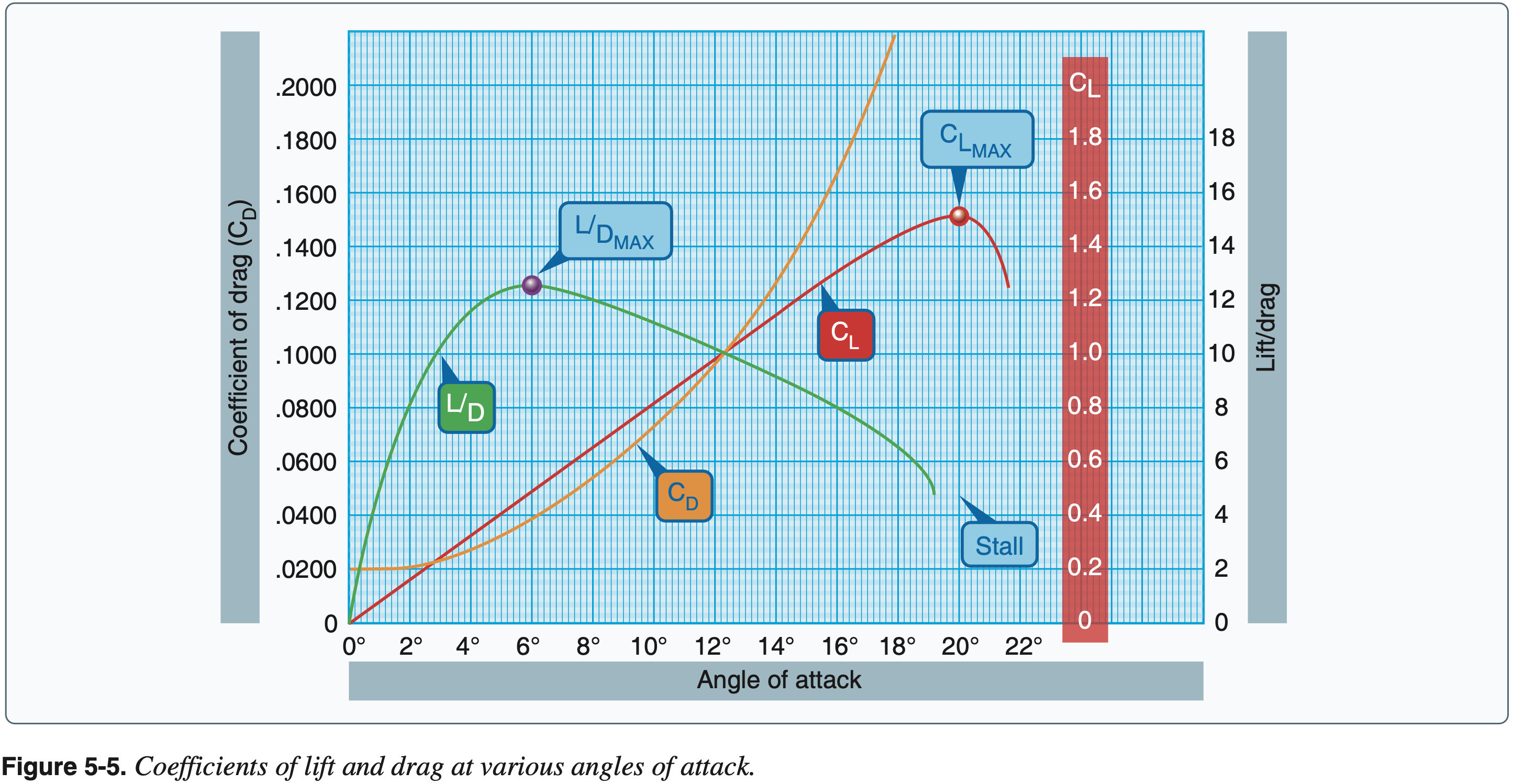
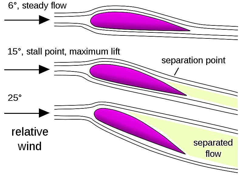
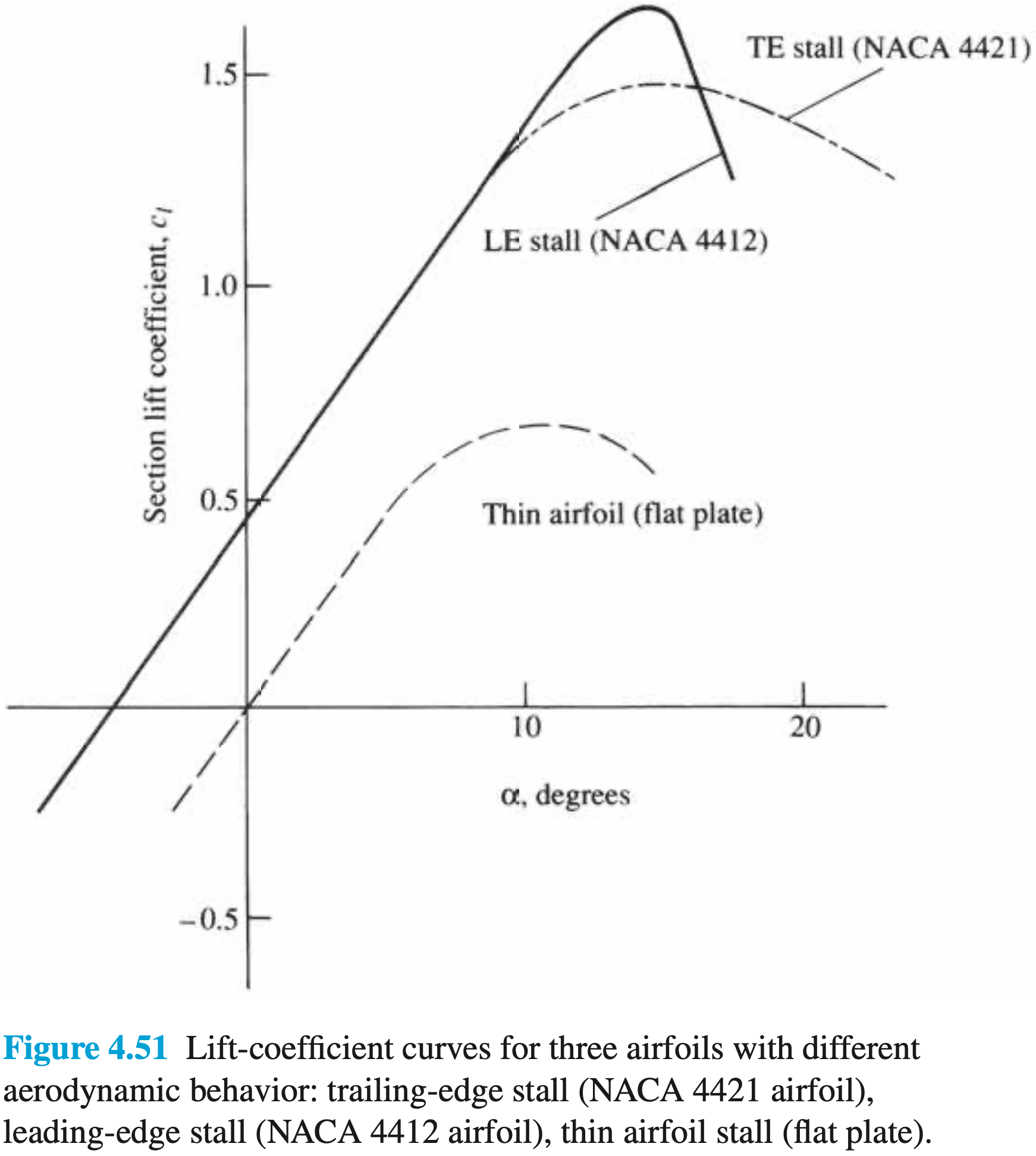
When the angle of attack becomes sufficiently large, there comes a point where it no longer results in an increase in
Critical Angle of Attack
The angle of attack which results in the maximum lift coefficient.
Any increase in the angle of attack beyond the critical angle of attack results in a decrease in the lift coefficient. Exceedence of the critical angle of attack is known as an aerodynamic stall.
NOTE
Stall is a function only of angle of attack. When the critical angle of attack is exceeded, the airfoil will stall, regardless of velocity.
However, most general aviation aircraft are not equipped with an angle of attack indicator, so we try to understand for various flight conditions and configurations what airspeed an aircraft will stall at. This is generally done assuming steady level flight or a steady turn. During steady-level flight at a fixed weight, CG location, and configuration, the relationship beween airspeed and stall is fairly clear - looking at the lift equation \eqref{eq.lift}, as the aircraft slows down
Stall Speed
The speed below which, for a specified aircraft configuration, an aircraft will stall.
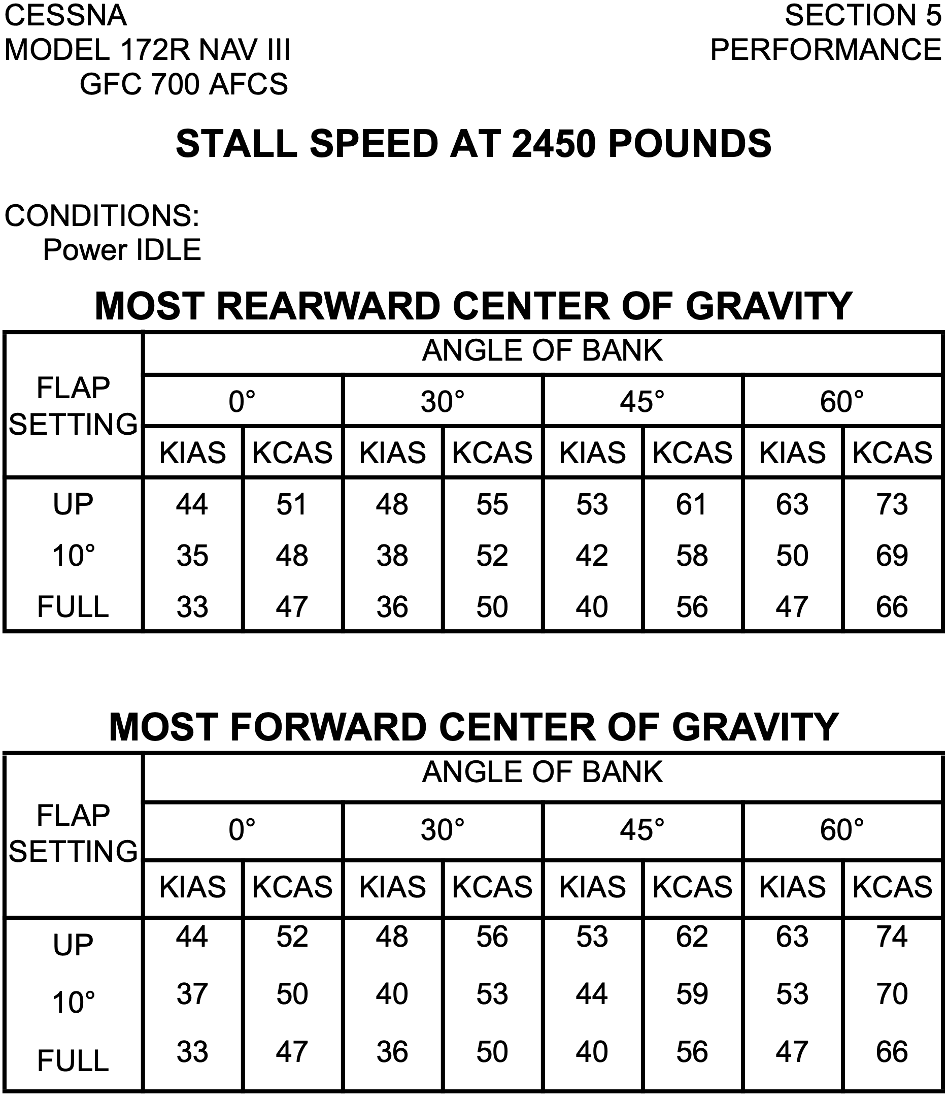
- When aircraft manufacturers publish stall speeds, these variables (weight, CG location, and configuration) must be selected to then provide the stall speed. Furthermore, the flight condition must be selected (level flight or turning).
- For example
is stalling speed in landing configuration with most forward CG during level flight at maximum landing weight with power idle. - See: 14 CFR §1.2 Abbreviations and symbols for definitions, although this just says for
that it is the stalling speed or the minimum steady flight speed in the landing configuration. - Part 25 of the CFRs defines airworthiness standards for transport category aircraft. 14 CFR §25.103 Stall speed defines the conditions under which stall speed is to be determined, and includes requirements, for example, that power is idle and CG is in most forward position.
- Part 23 of the CFRs defines airworthiness standards for normal category aicraft. 14 CFR §23.2110 Stall speed says that the stall speed determination must account for the most adverse conditions for each flight configuration.
- See: 14 CFR §1.2 Abbreviations and symbols for definitions, although this just says for
- In practice the actual stall speed may be different than the published value.
- Also,
, at least in the C172SP seems to be given in KCAS. In this example it is 48 KCAS, which corresponds to 40 KIAS.
- Also,
- The stall speed increases in proportion to the square root of the load factor.
- Looking at the stall speed at the critical angle of attack:
we can see that - See Load Factors below
- Looking at the stall speed at the critical angle of attack:
- The stalling speed increase as CG moves forward and decreases as it moves rearward.
- This is because as the CG moves forward, there is an increase in downward force produced by the horizontal stabilizer to balance out the moments. But to balance out this increase in downward force, more lift must be produced by the wings. Therefore at a given flight condition, the aircraft with the forward CG will require more lift than that with a rearward CG, meaning a higher minimum speed to maintain the flight condition.
Drag
- There are a couple of ways to catagorize types of drag.
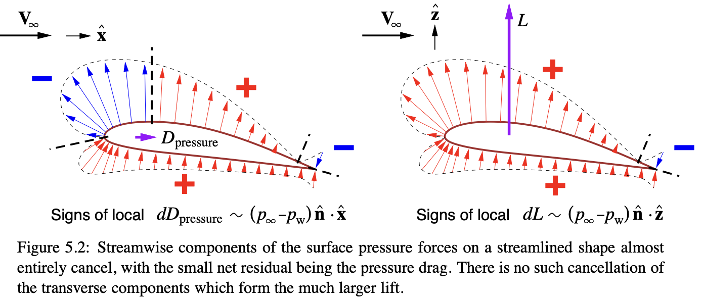
- Pressure drag is due to normal forces
- Skin friction drag is due to shear forces
- Another catagorization is
- Parasitic drag a pure "unproductive" loss
- Induced drag a necessary consequence of creating lift
- For the purposes of these notes, we'll focus on the latter catagorization.
- However, the former catagorization is useful to help understand which type of drag is dominant for various bodies.
- A blunt body is defined as one where pressure drag is dominant, and a streamlined body is one where skin friction drag is dominant.
- Parasitic drag
- Profile drag
- The sum of skin friction drag and form drag for an airfoil.
- When considering a more complex 3D body (where interference drag exists) profile drag becomes synonomous with parasitic drag.
- Skin friction drag
- Due to shear stress acting on surface
- Not captured by inviscid flow theory
- Form drag
- Due to flow separation
- A type of pressure drag
- Also known as profile drag
- Not captured by inviscid flow theory (see d'Alembert's paradox)
- Interference drag
- Due to the presence of multiple bodies
- Caused by mixing of airflow streams
- A type of pressure drag
- Profile drag
- Induced drag
- Drag due to lift
- Occurs on finite, lifting wings
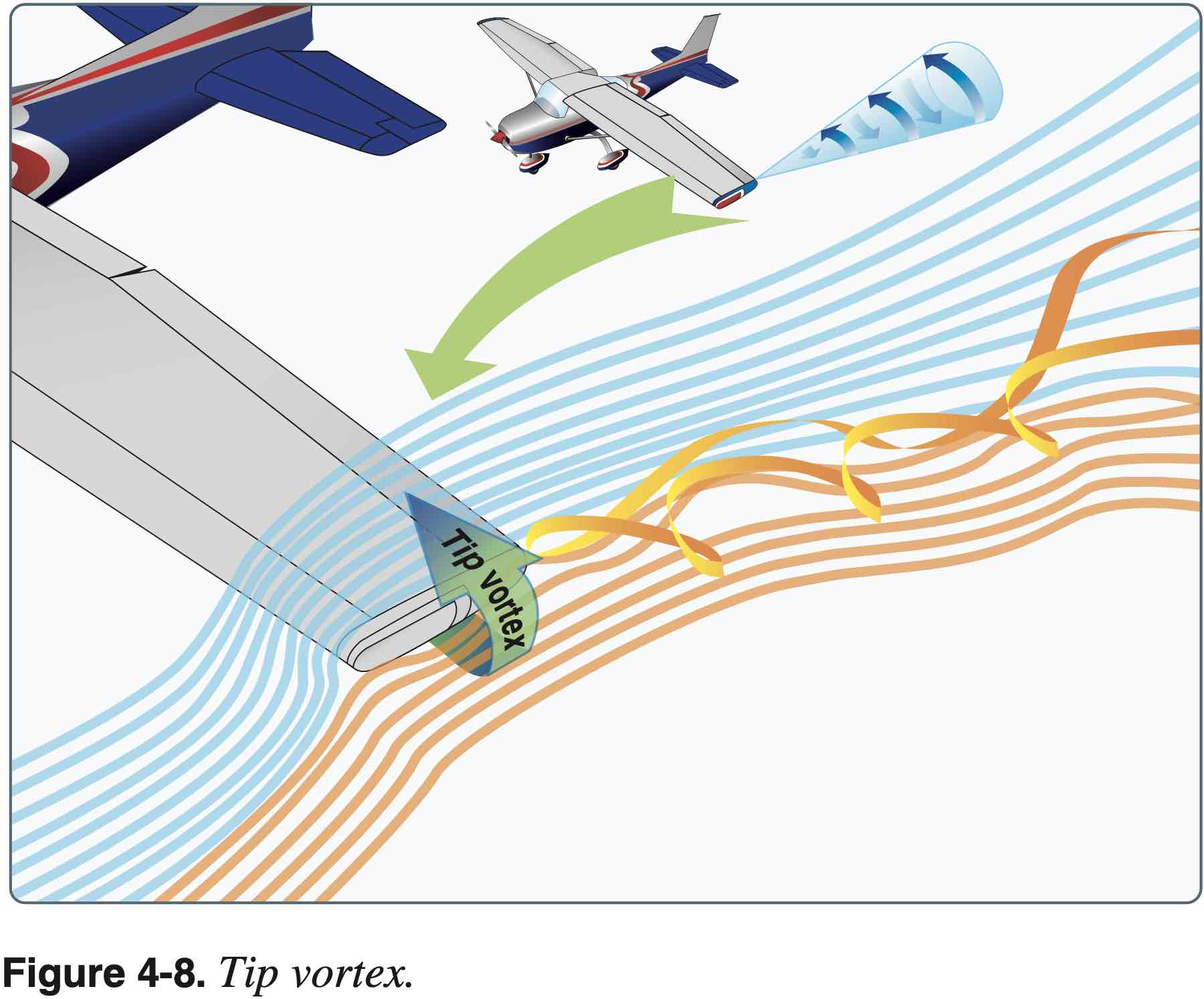
- The spanwise flow around the wingtips, which induce the wingtip vortices, also changes the pressure distribution in the direction of the flow, rotating the lift vector and adding an additional component of drag.
- Thus, is a type of pressure drag.
- Induced drag is present when analyzing inviscid, incompressible flow.
- See: NASA Induced Drag Coefficient
- Induced drag coefficient
is given by the following where is the Oswald efficiency - Lifting line theory shows that the optimum (lowest) induced drag occurs for an elliptic distribution of lift from tip to tip.
- The efficiency factor
is equal to 1.0 for an elliptic distribution and is some value less than 1.0 for any other lift distribution.
- The efficiency factor
- For a wing, the total drag coefficient,
is equal to the base drag coefficient at zero lift plus the induced drag coefficient .
- Wave drag - compressible fluid near speed of sound
- A type of pressure drag
- Occurs in inviscid flow theory
- In supersonic flow d'Alembert's paradox does not occur
Understanding which type of drag is dominant helps us understand why aircraft are designed the way they are. For example, for supersonic aircraft, wave drag becomes dominant and to minimize wave drag sharp leading edges and swept wings are used.
Understanding of induced drag is also important to avoid wingtip vortices and help us understand ground effect. From FAA-H-8083-25B Pilot's Handbook of Aeronautical Knowledge Chapter 5: Aerodynamics of Flight:
When the wing is at a height equal to its span, the reduction in induced drag is only 1.4 percent. However, when the wing is at a height equal to one-fourth its span, the reduction in induced drag is 23.5 percent and, when the wing is at a height equal to one-tenth its span, the reduction in induced drag is 47.6 percent.
For example, when doing a soft-field takeoff want to get off the ground soon but stay in ground effect to build airspeed. Also when taking off, don't retract landing gear before a positive rate is established, or the plane can sink if leaving ground effect prematurely. When leaving ground effect, can experience a nose-up pitching moment as downwash on the horizontal tail increases.
Total Drag
Generally lower case letters are used to denote profile values whereas capital letters are used to denote wing or aircraft values. For example,
Substituting this in we get
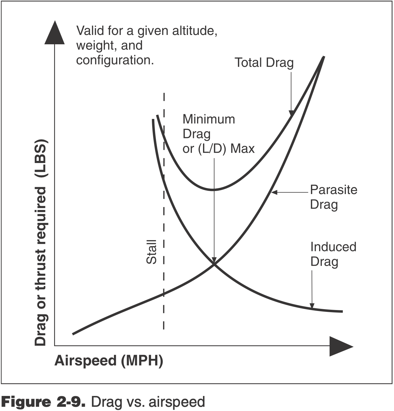
- Total drag is composed of a sum of a
term (parasitic drag) and a term (induced drag) - At low airspeeds induced drag dominates and at high airspeeds parasitic drag dominates

Coordinated Flight
In a coordinated turn there is no lateral acceleration. Uncoordinated flight is flying with the wrong turn rate for a given bank angle. Figure 5-35 in FAA-H-8083-25B Pilot's Handbook of Aeronautical Knowledge Chapter 5: Aerodynamics of Flight is not helpful. The reality is the direction of the net lift vector changes in uncoordinated flight so as to not be strictly in the
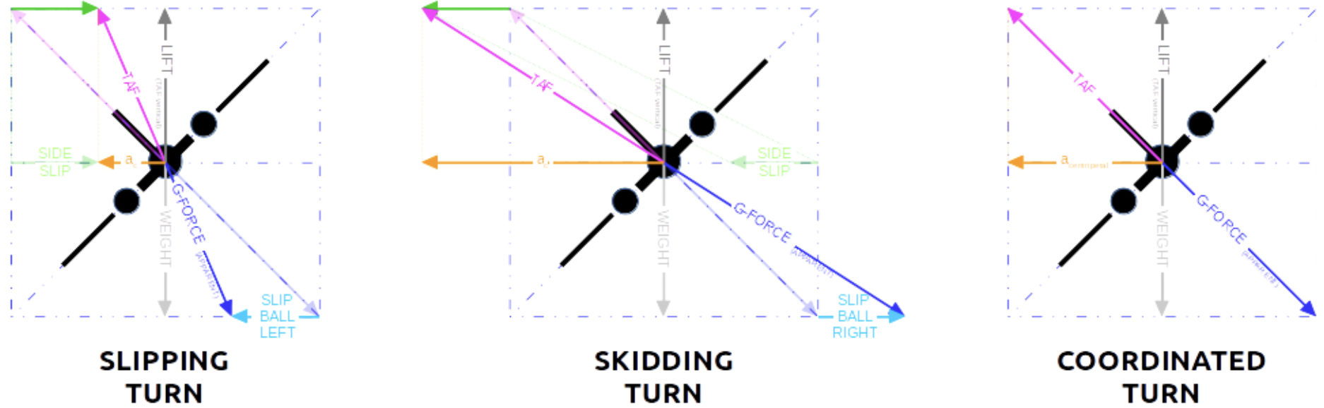
Slipping and Skidding Turns
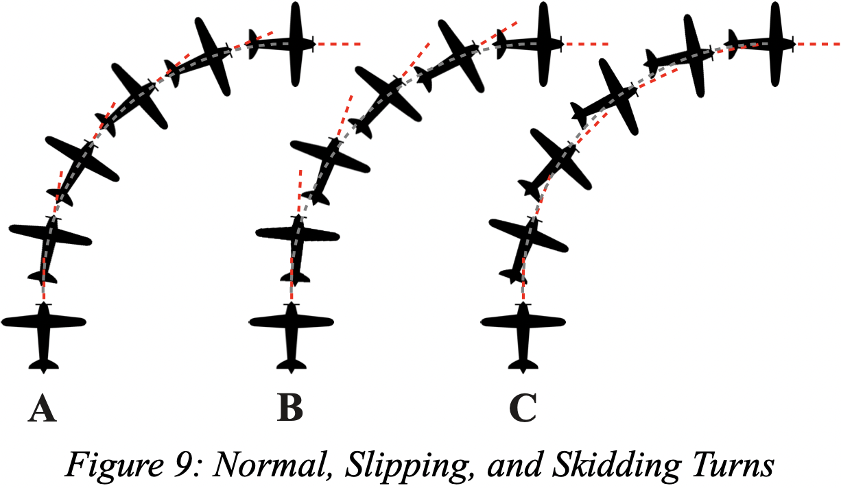
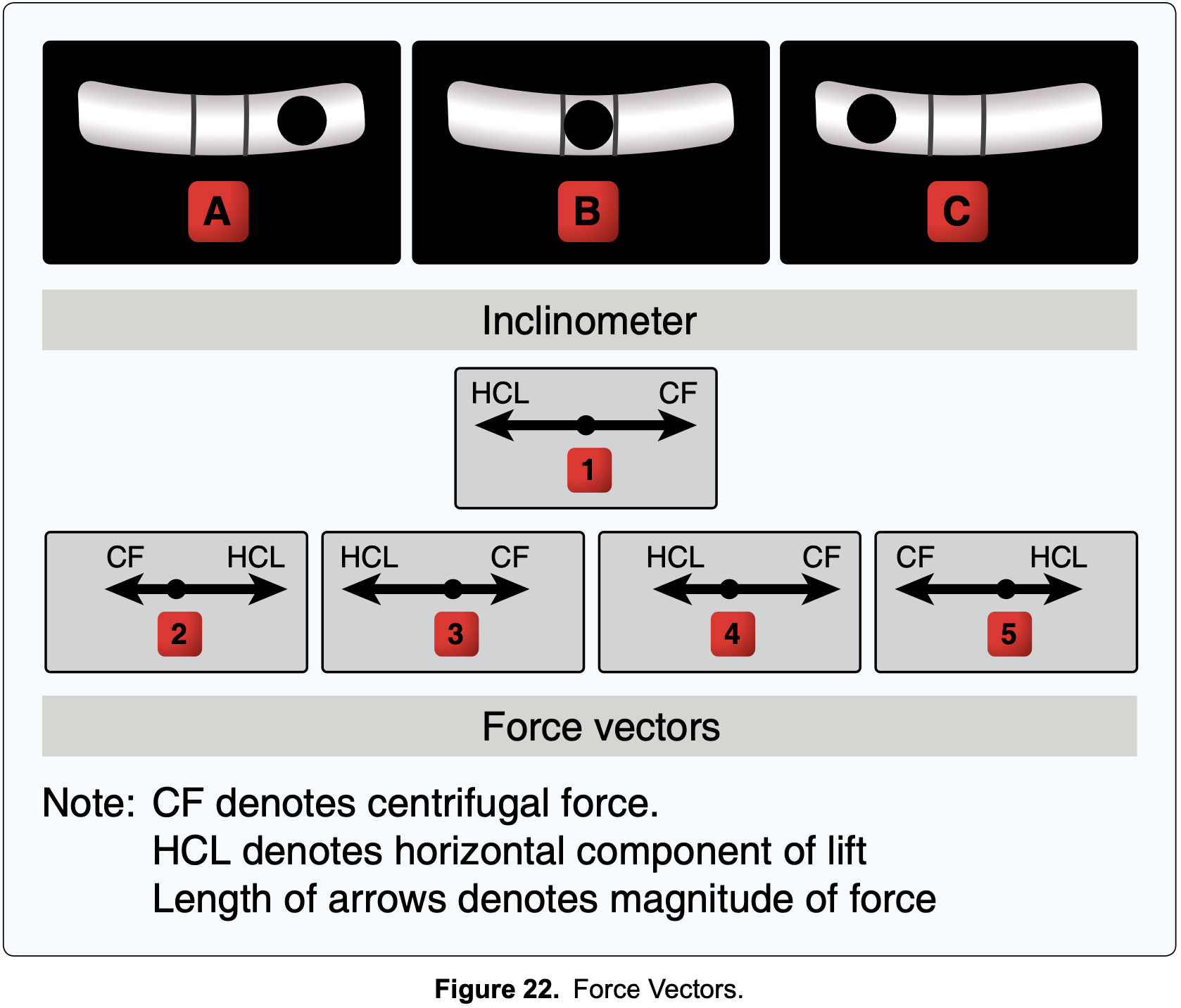
- The figure below demonstrates the difference between a coordinated turn with
- (A) appropriate rudder
- (B) not enough rudder, called slipping
- (C) too much rudder, called skidding
- In right turn if you are:
- Slipping, you need to apply more right rudder
- Skidding, you need to apply more left rudder
- Think of skidding like drifting in a car - too much turn angle for radius of turn, so need to apply rudder in opposite direction
- One thing this image doesn't capture is how in these different scenarios the radius of turn (should?) be different
SAFETY
Skidding is generally considered more dangerous than slipping due to the lowered wing moving more slowly, at a higher angle of attack, and with more aileron and hence being the wing which may stall first. Should this occur, the lowered wing would drop even further rolling the aircraft into a spin.
Turn Rate
Consider an aircraft with roll angle
Putting this together we get
From this we can see that there is a unique solution for
therefore the rate of turn is given by
This relationship is helpful to see as it indicates an increase in bank angle results in a faster turn rate, as does a decrease in airspeed. The latter might seem somewhat counter-intuitive but is important to know as it comes into play in many maneuvers which we fly, such as lazy-eights.
Distance Lost in Gliding 360
- Knowing how much altitude is lost in a gliding 360 degree turn can be helpful to know for the purposes of planning engine-out landings
- The following uses numbers from a C172S to help understand what might be a reasonable value to expect
- Use the following values
- Airspeed is
, or 68 knots which is 35 m/s - Bank angle of 30 degrees
- Glide ratio of 1.5 nm per 1000 ft lost
- Airspeed is
- Recall the expression for turn rate from above
- This gives a turn rate of a little bit more than 9 degrees per second, or 40 seconds to complete a 360.
- At 68 knots in 40 seconds would travel about 0.76 nm
- We didn't take into account the extra induced drag due to higher load factor, which in a 30 degree banked turn is only
- So in 0.76 nm would lose about 500 ft going straight, which we can increase 15% or so
- We didn't take into account the extra induced drag due to higher load factor, which in a 30 degree banked turn is only
- So a good number to assume for C172: about 600 ft lost in 360 gliding turn.
More Aerodynamic Theory
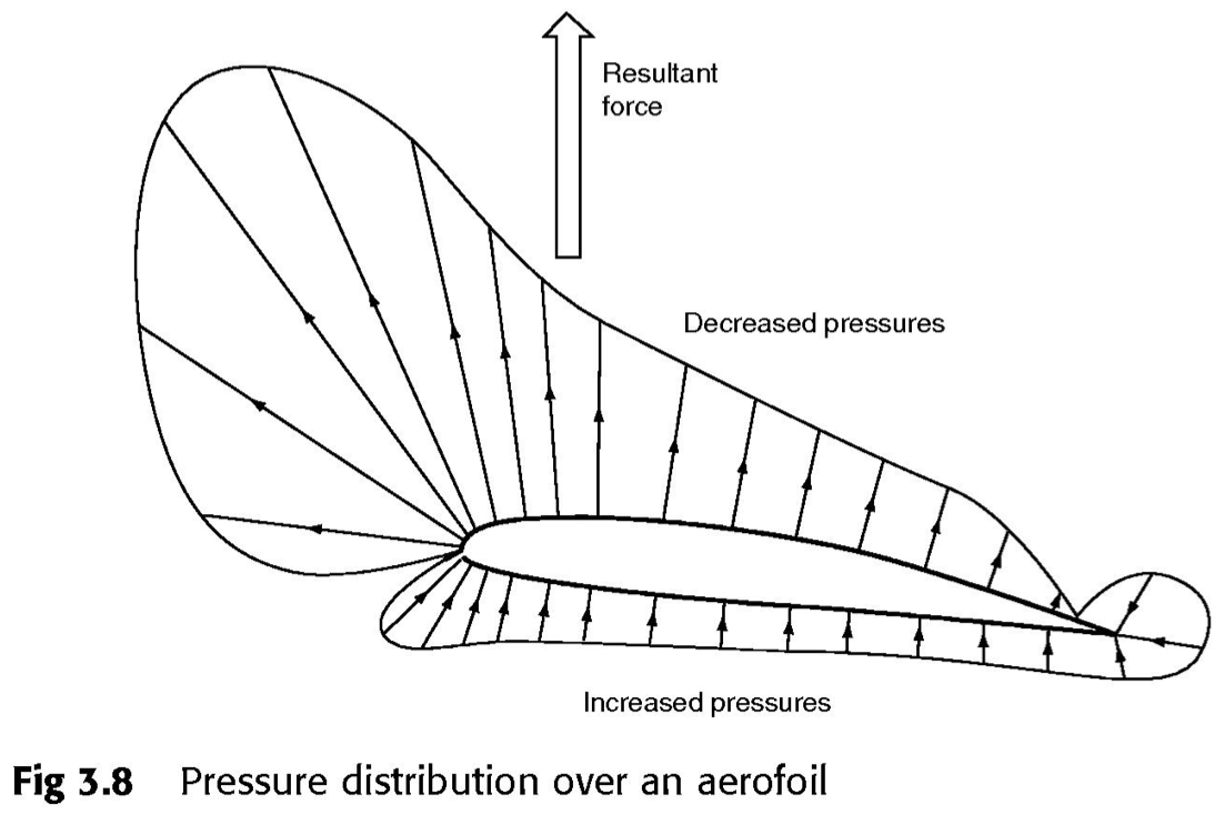
Center of Pressure (CP)
A single point at which the lift and drag forces on an airfoil can be applied about which they exert zero moment.
- Center of pressure
- The location of the center of pressure moves significantly with a change in angle of attack.
- When angle of attack increases, CP moves forward.
- When angle of attack decreases, CP moves rearward.
- See NASA Center of Pressure
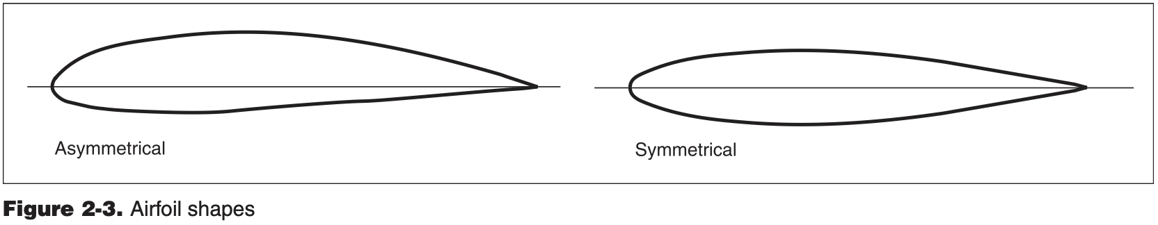
- The location of the center of pressure in a symmetrical airfoil remains relatively constant as the angle of attack changes, but in an asymmetrical airfoil, the center of pressure moves forward as the angle of attack increases and rearward as the angle of attack decreases.
Aerodynamic Center
Point at which the pitching moment coefficient for the airfoil does not vary with angle of attack.
- Aerodynamic center
- Used to simplify calculations in aerodynamic analysis
- Located roughly at quarter-chord.
Aside
- Equal transit time - myth that incorrectly assumes that the parcels of air that divide at the leading edge of an airfoil must rejoin at the trailing edge, forcing the air traveling along the longer upper surface to go faster. wikipedia
- "The Step" - It was a myth that I had heard somewhere before, where a pilot had said by climbing slightly through their desired level-off altitude and descending into it, allowed them to then cruise at a higher airspeed than would have been possible if they had just leveled off upon reaching the target altitude without overshoot.
- This is not true - see the drag vs velocity curve. For a given velocity, there is one drag value. So for a given power setting (as long as not "behind the power curve") there cannot be two different airspeeds/AOA, while lift and drag are the same.
- Now, lift could stay the same if for a lower airspeed and larger AOA these effects balanced out. But
changes pretty much linearly with AOA, and quadratically with velocity. So for lift to remain the same, these would have to balance exactly, which is impossible. - Basically for fixed power setting there is one equilibrium level flight condition.
- Mysteries Of Flight: On The Step
- Winglets
- Changes lift distribution
- Increases wingtip bending moments
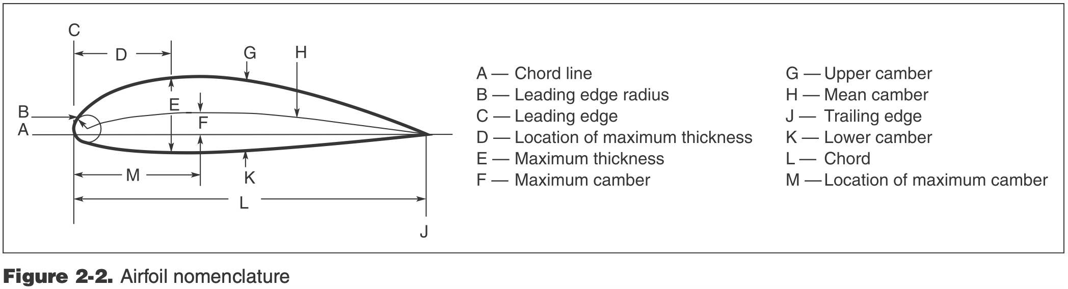
Airfoil Design Characteristics
- Airfoil - the cross-sectional shape of an object whose motion through a gas is capable of generating significant lift.
- Recall lift
- Airfoil vs. wing (2D cross-section vs. 3D)
- Induced drag is only a 3D phenomenon
- Three primary characteristics of a lift-generating airfoil
- Angle-of-attack
- Controllable by the pilot during flight by changing aircraft attitude
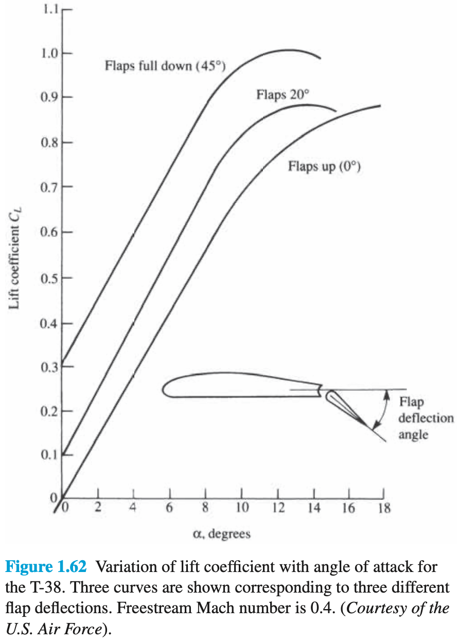
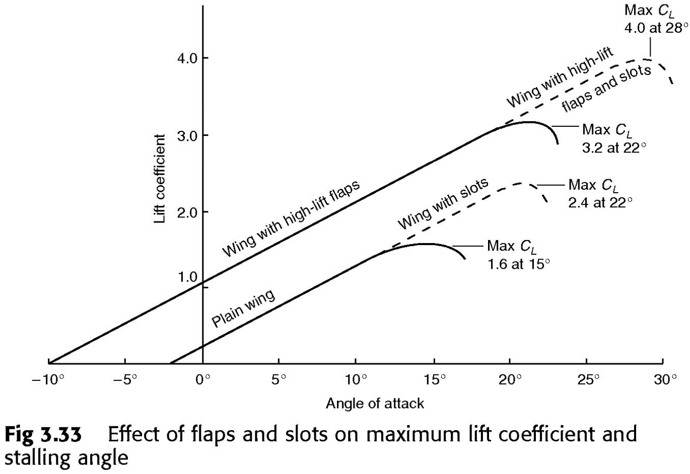
- Camber
- Controllable via flaps
- Thickness
- Fixed in aircraft design
- Angle-of-attack
- Change these variables to change lift and drag
- Consider different phases of flight
- Not just maximum lift and drag, but rather the curves
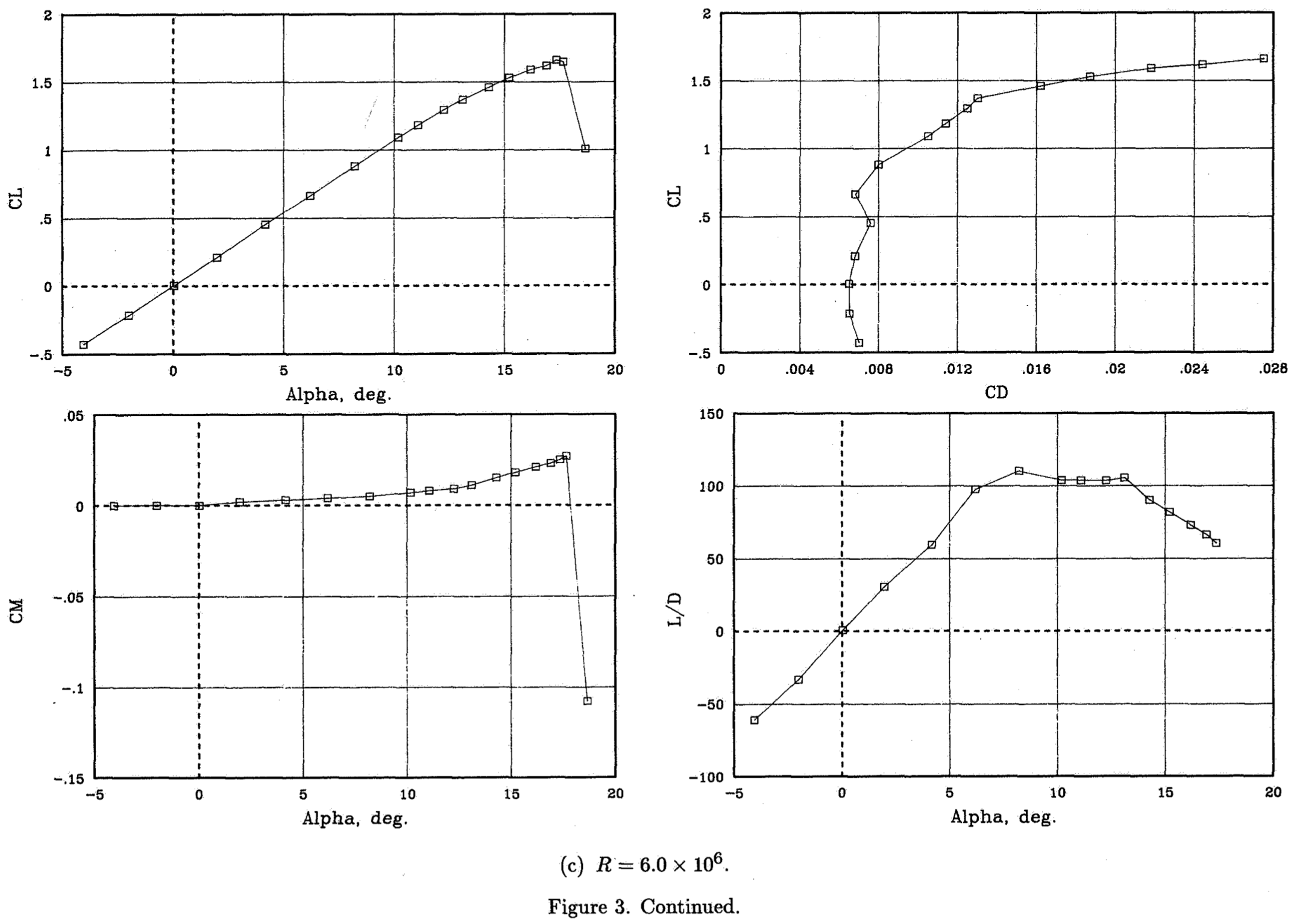
- Common plots that show how aerodynamic performance changes
vs. - lift versus angle of attack vs. - lift versus drag vs. - also versus angle of attack
- Airfoil stall characteristics
- Flaps changing airfoil shape
Common Aerodynamic Plots
- A drag curve is a generic term to describe a plot of drag (or the drag coefficient) versus a number of other variables.
- If one of these variables is lift (or the lift coefficient) it is called a drag polar or drag bucket.
Some Notes on Wings
- The three characteristics of a lift-generating airfoil were given above
- There are additional characteristics which affect lift of a wing
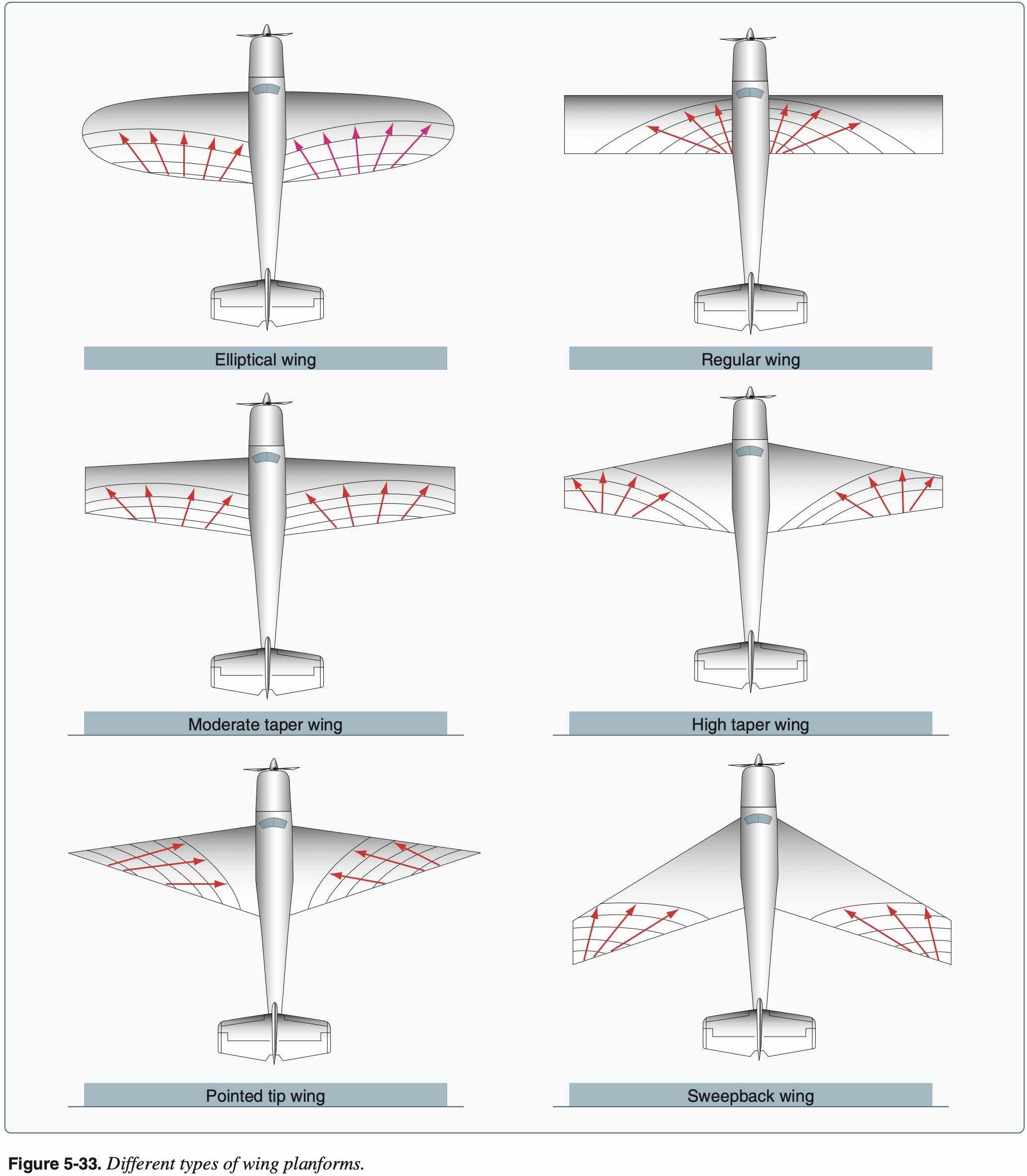
- Planform shape
- Rectangular
- Elliptical
- Delta
- Geometric twist
- Changing incidence angle of the wing along the wing
- Usually this is done to reduce the angle of attack towards the wingtip to delay stall there and provide better stall characterstic of stalling at the wing root first
- Aerodynamic twist
- The angle between the zero-lift angle of an airfoil and the zero-lift angle of the root airfoil.
- In essence, this means that the airfoil of the wing would actually change shape as it moved farther away from the fuselage.
- Typically the zero-lift line is rotated downward toward the wing tips, similar to geometric twist.
- Aspect ratio
- Planform shape
- These characteristics affect not just the aerodynamics of the wing and airplane, but also it's stability and controllability
Airplane Stability and Controllability
Overview
- Controllability
- Capability of aircraft to respond to pilot inputs, especially with regard to flight path and attitude
- Ease of roll, pitch, yaw
- If an aircraft fails to respond to a pilots inputs (or responds in the opposite manner), then it lacks controlability, for example too much adverse yaw when turning
- Affected by CP movement
- Maneuverability
- Quality of airplane that permits it to be easily operated and withstand stresses imposed on it
- Briskness of roll, pitch, yaw
- Stability
- The behavior or response of an aircraft when perturbed from its equilibrium flight condition.
- Example
- An airline would be highly controllable but not very maneuverable - it does respond to pilot inputs predictably and easily, changes in aircraft velocity (roll, pitch, yaw) are slow.
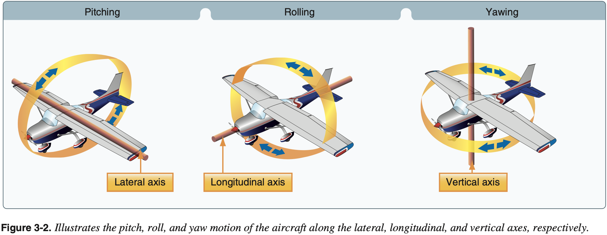
Aircraft axes system is below where
- longitudinal axis - lateral axis - vertical axis
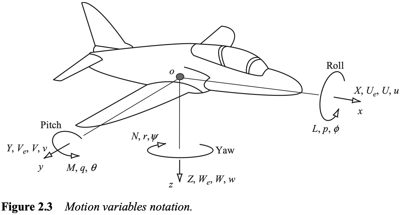
Note: when we talk about stability it can be confusing because longitudinal stability in not stability about the longitudinal axis, but rather in the longitudinal direction, so just keep that in mind.
Types of Stability
- Perturbations can be caused by wind, turbulence, thermals, or pilot inputs
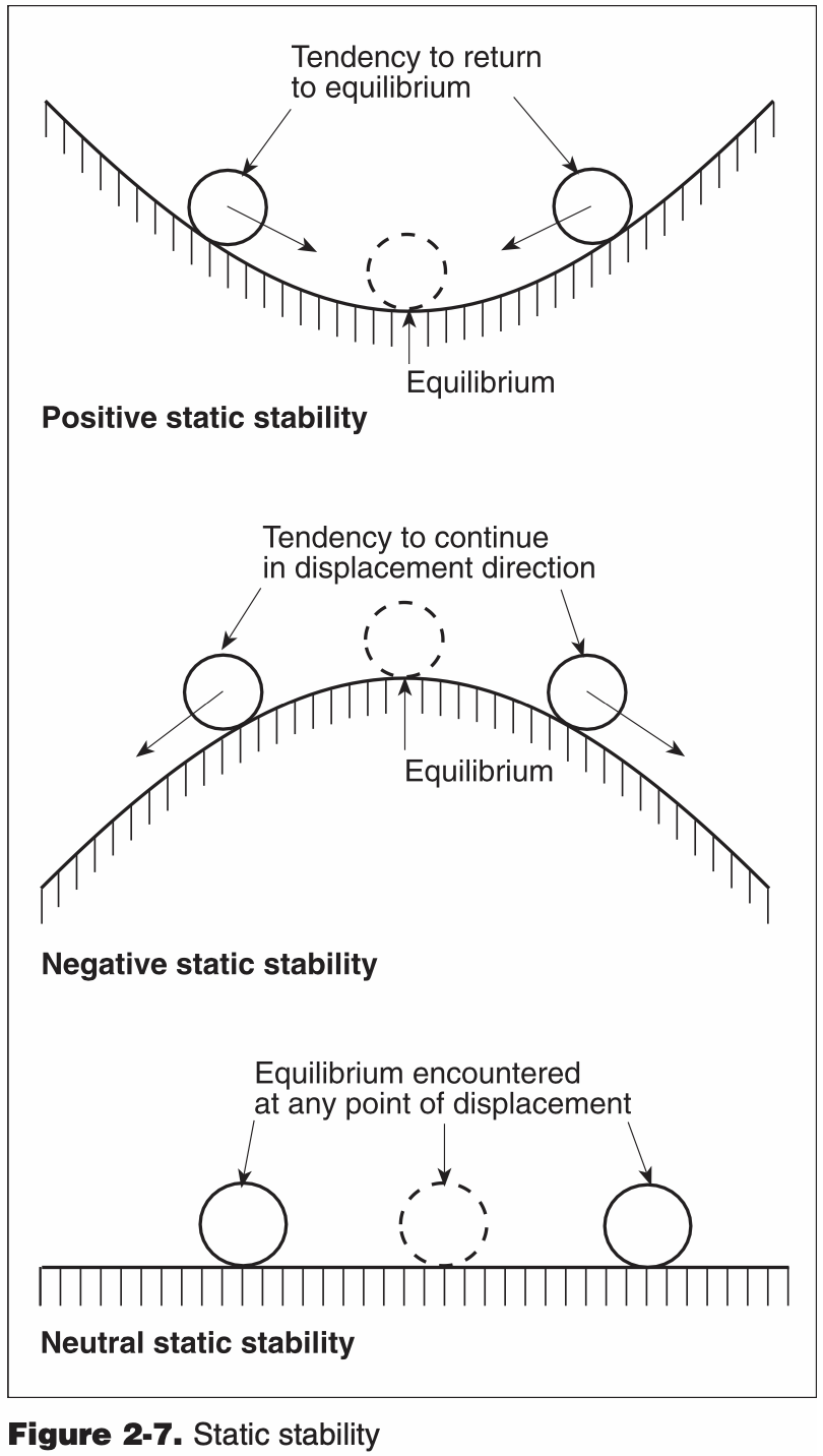
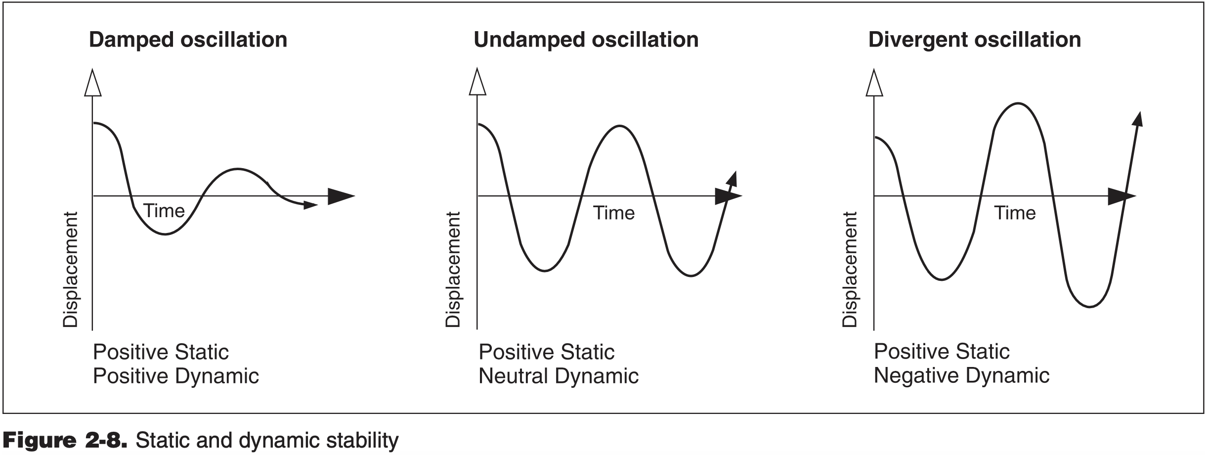
- Static versus dynamic stability
- Initial tendency
- Eventual tendency
- Types of stability
- Positive
- Neutral
- Negative
- Stability about each axis
- Longitudinal
- Lateral
- Directional
- Note: lateral and directional stability more closely coupled
Aircraft Design for Stability and Controllability
- Stability and Controllability are determined largely by aircraft design choices, and often tradeoffs between the two are made depending on the requirements of the aircraft
- These design choices affect more than just stability, and so are balanced with other requirements as well
- For example sweep is also used to improve aerodynamic efficiency at higher speeds
- In larger modern airplanes, stability and control are also provided "artificially" through feedback systems
- May encounter these systems in more expensive and modern GA aircraft as well
- When we consider the restoring moments created on the aircraft due to these different design choices, recall that they are about the aircraft CG
- More on CG location below
- Below we focus on some basic aircraft geometries for stability
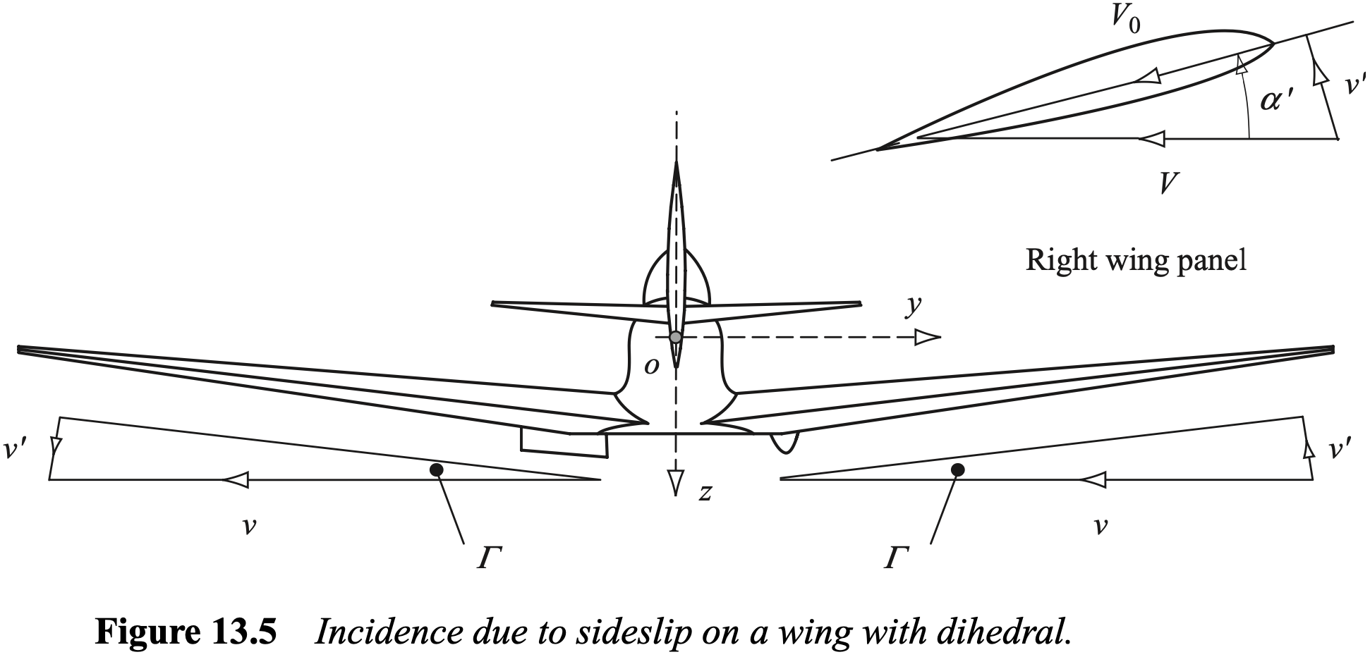
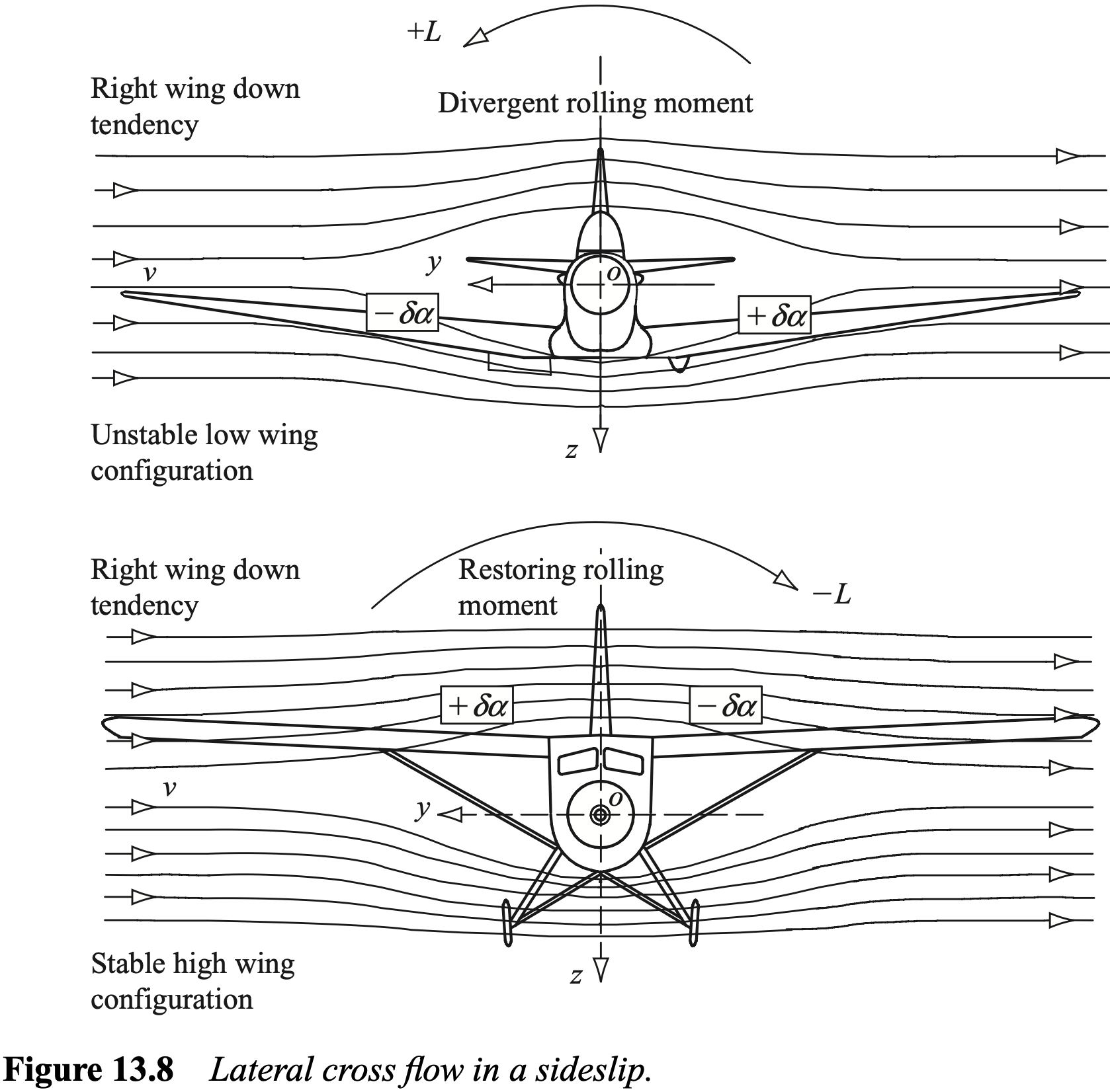
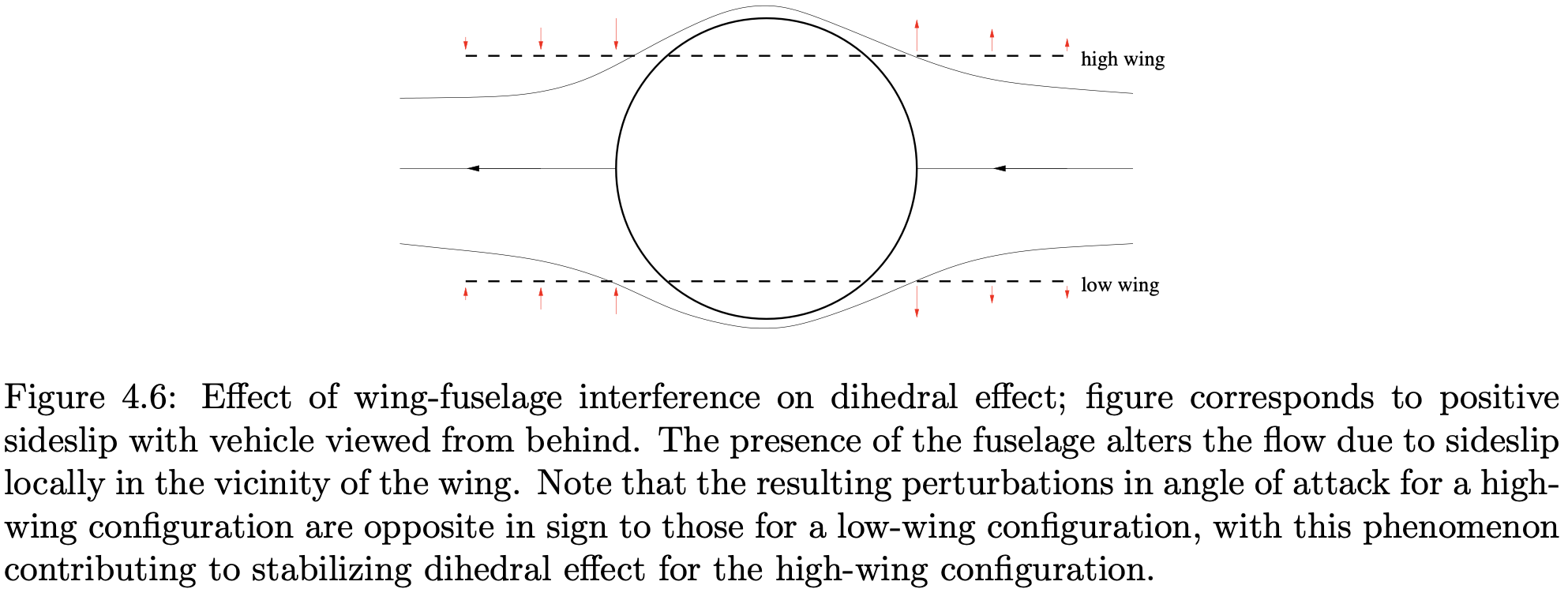
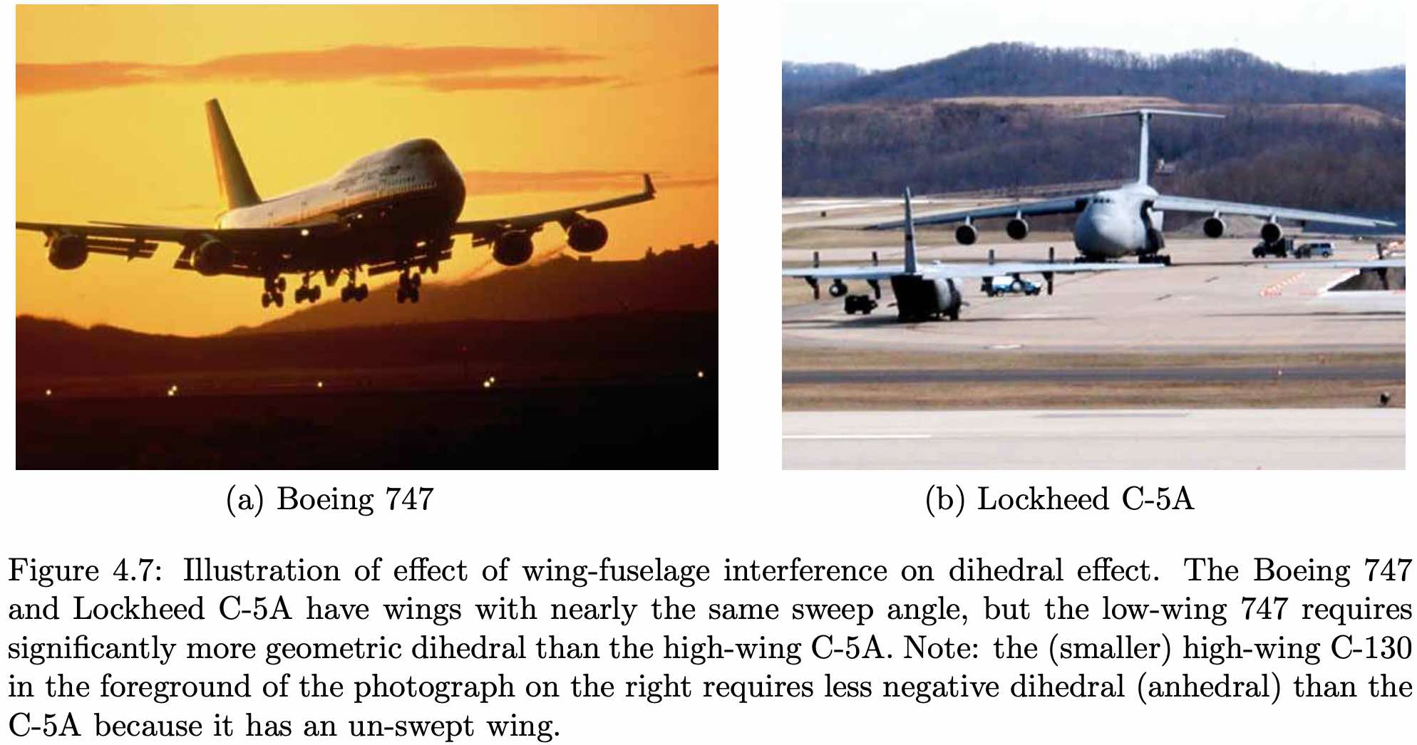
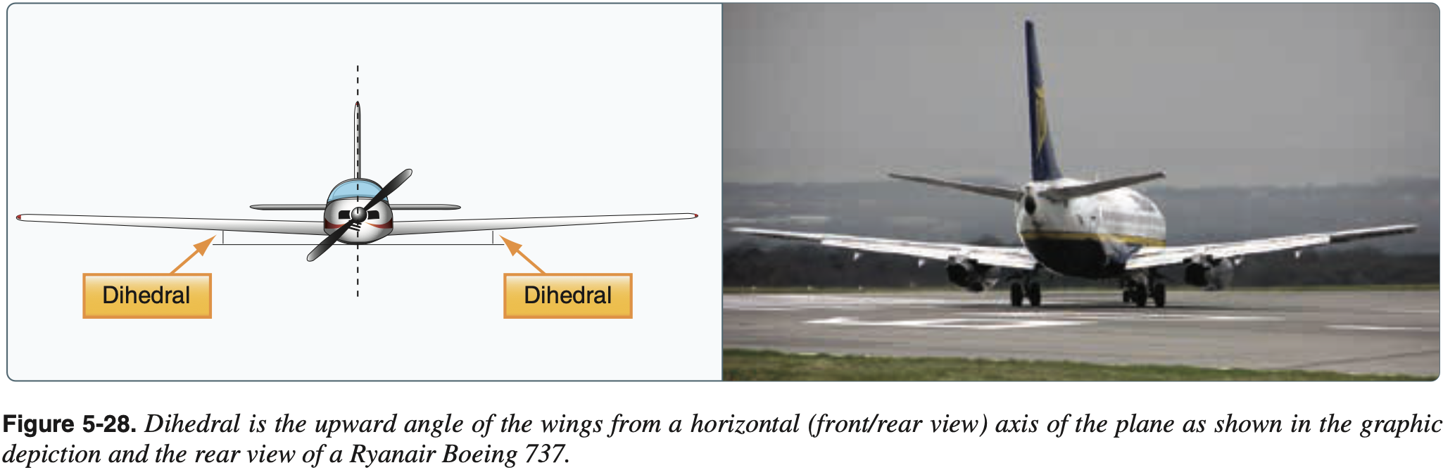
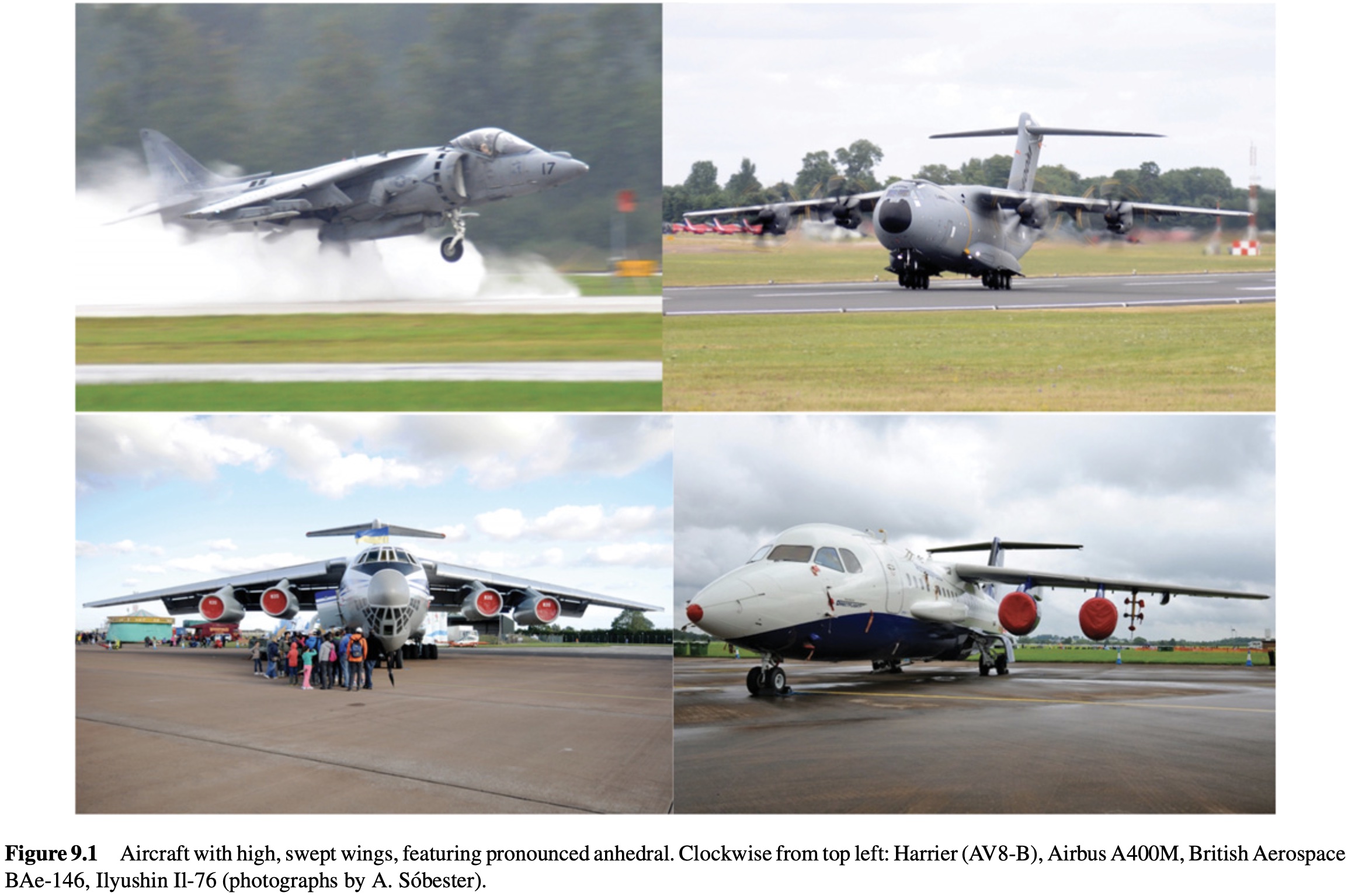
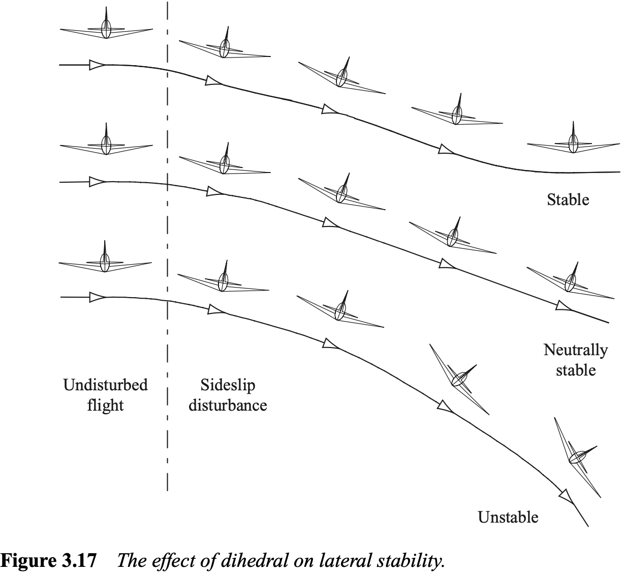
- Dihedral / anhedral
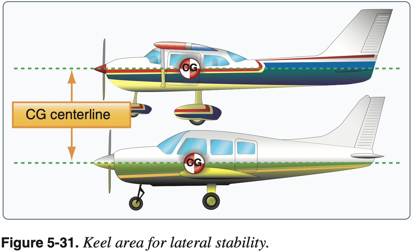
- Generally biggest contributor to lateral stability
- Related to high versus low wing location and keel area
- Increases angle of attack on dropped wing
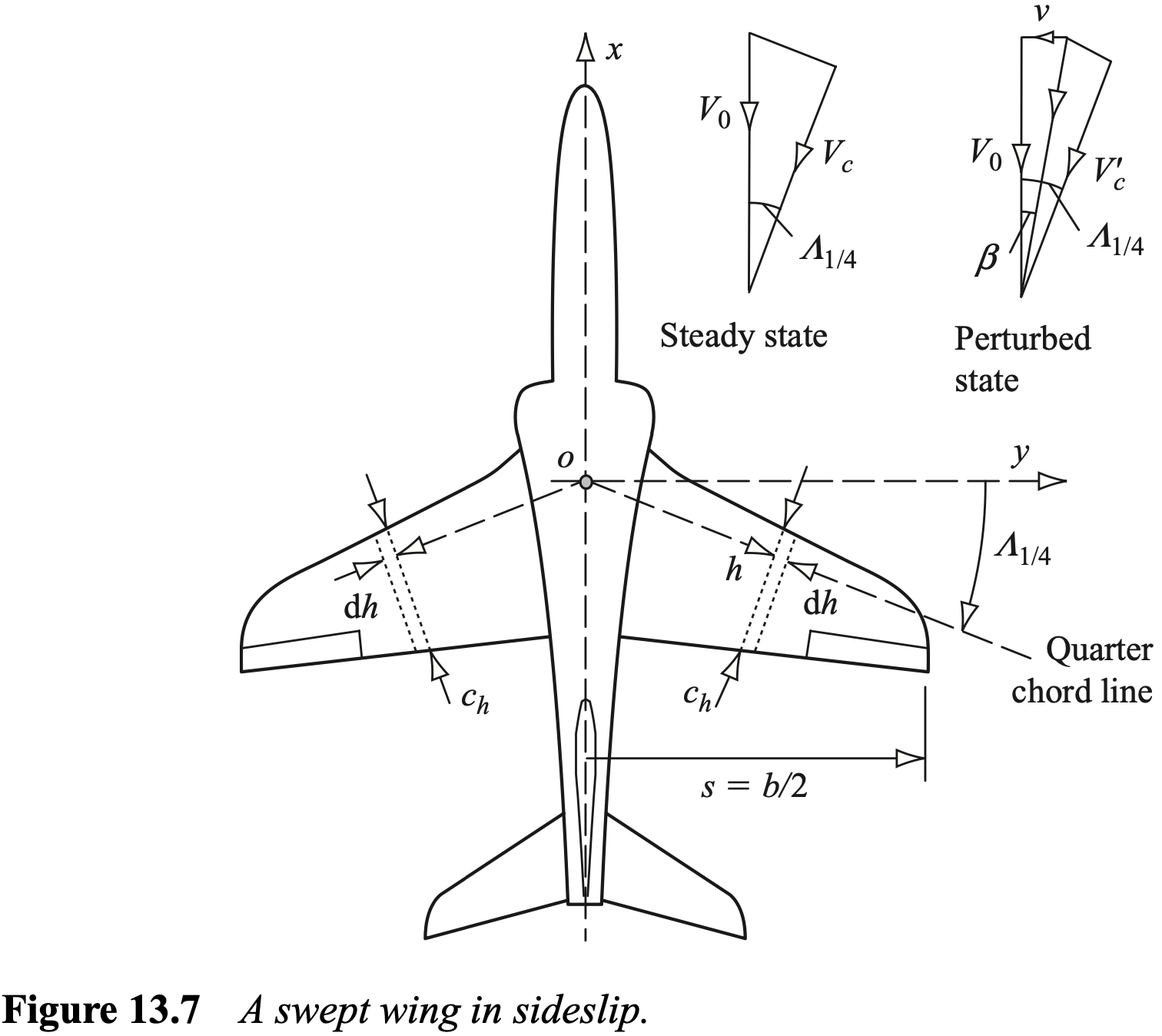
- Sweep
- Lateral stability
- Increases angle of attack on dropped wing
- Horizontal Stabilizer
- Longitudinal stability
- Affected by size and location of aerodynamic surfaces with respect to CG along longitudinal axis
- Slightly nose-heavy for pitch stability
- Size
- Location
- Horizontal stabilizer far from datum, has a lot of leverage
- Vertical location of stabilizer and downwash
- T-tail versus conventional tail
- Downwash from wings on tail
- Provides downward force in level flight, even when horizontal tail is level
- When speed is reduced, downwash on tail is reduced, aircraft tends to pitch down
- Closing the throttle also decreases downwash on tail
- Longitudinal stability
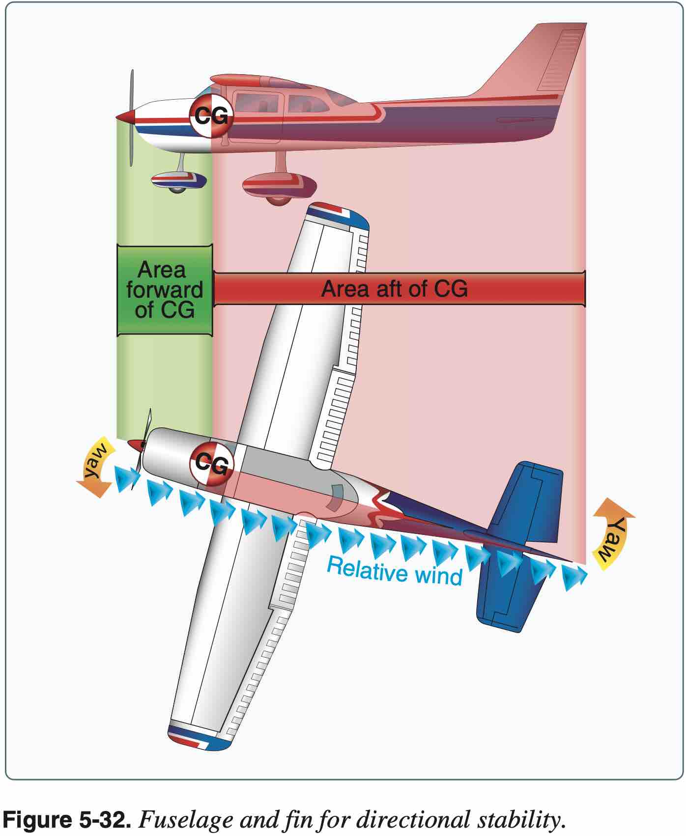
- Vertical stabilizer
- Directional stability
- Weathervane effect
- Thrust line
- Fuselage
- Taper
- Twist
- Engine nacelles
- Dihedral / anhedral
- Wing planform and effect on stall characteristics
- In general, with a lot of the above design choices, given the perturbation of the aircraft consider how this affects aerodynamic forces on different surfaces, and the moment that force creates about the center of gravity
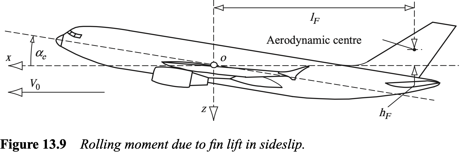
- For example, rolling moment created on vertical stabilizer
- Stability modes
- Longitudinal
- Phugoid
- Short period
- Lateral-directional
- Roll subsidence
- Dutch roll
- Spiral divergence
- Longitudinal
- Important takeaway here is to develop a better understanding for aircraft aerodynamics, and expectations for how and why an aircraft you will be flying behaves the way it does so.

Center of Gravity Effect
- The above design choices are something the aircraft designer chooses - not the pilot
- The pilot can affect stability and control via aircraft loading and the corresponding CG location
- Longitudinally
- Primary axis along which we consider CG location
- Laterally
- Fuel burn
- Longitudinally
- CG effects on spin and stall recovery
- CG effects on performance
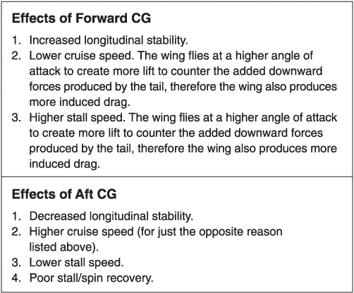
- CG too far forward
- Longer takeoff distance
- Higher stalling speed
- Reduced elevator effectiveness
- Increased stability
- Reduced fuel economy and speed
- Limit imposed by making sure enough elevator authority to hold the aircraft in normal glide with power off / aircraft's landing characteristics are suitable.
- CG too far rearward
- Worse than too far forward
- Unstable
- Reduced elevator effectiveness
- May not be able to recover from a spin
- Limit imposed by stability (making sure aircraft has correct damping) / stall recovery
Turning Tendency
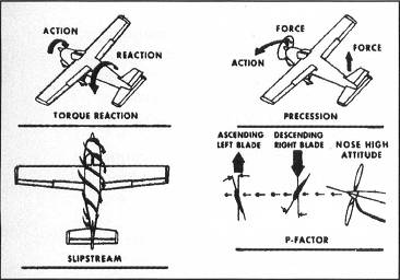
- Note: most United States built aircraft engines rotate the propeller clockwise, as viewed from the pilot's seat.
- Four causes of turning tendency below.
- Torque reaction from engine and propeller
- Tends to push left wing down
- Aircraft may be designed to minimize this, for example by offsetting the engine
- During takeoff roll, with more force on left gear there is more friction and a left-turning tendency
- Corkscrewing effect of the slipstream
- Slipstream from propellor tends to hit the vertical stabilizer on the left side causing additional left turning tendency
- Gyroscopic action of the propeller
- Pitch or yaw generates a force 90 degrees in the direction of rotation
- More prominent in tailwheel aircraft when rotating during takeoff roll
- See section below
- Asymmetric loading of the propeller (P-factor)
- Local angle of attack on propeller is not uniform
- For example, at large (aircraft) angles of attack the descending blade (on the right side of the aircraft) will have a larger local angle of attack than the ascending blade (on the left side). Thus there will be asymmetric thrust that is higher on the right side of the aircraft causing a yawing moment to the left.
- The "P" stands for pitch of the prop
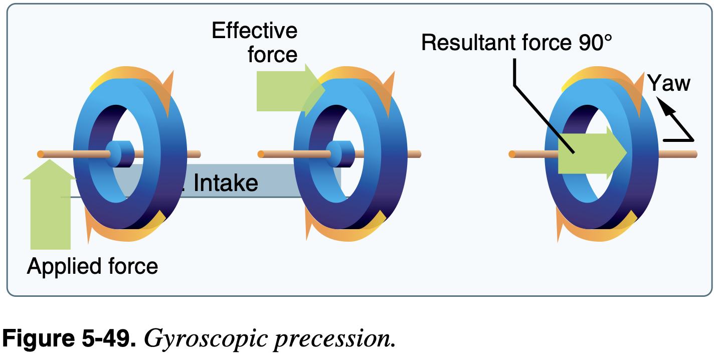
Aside: Gyroscopic Precession
- The theory here is applicable both to a turning propellor and turning gyroscopic instruments
- Principles
- Rigidity in space
- Precession
- These principles areapplicable to understand the gyroscopic action of the propeller as well as gyroscopic instruments.
- First consider precession
- Consider a rotating disc.
- moment of momentum (or angular momentum) vector, parallel to rotation - Moment of momentum measures an objects tendency to continue to spin, it describes the rotary inertia of a system in motion about an axis.
- Apply couple (or pure moment)
perpendicular to - Newton's second law for rotation is
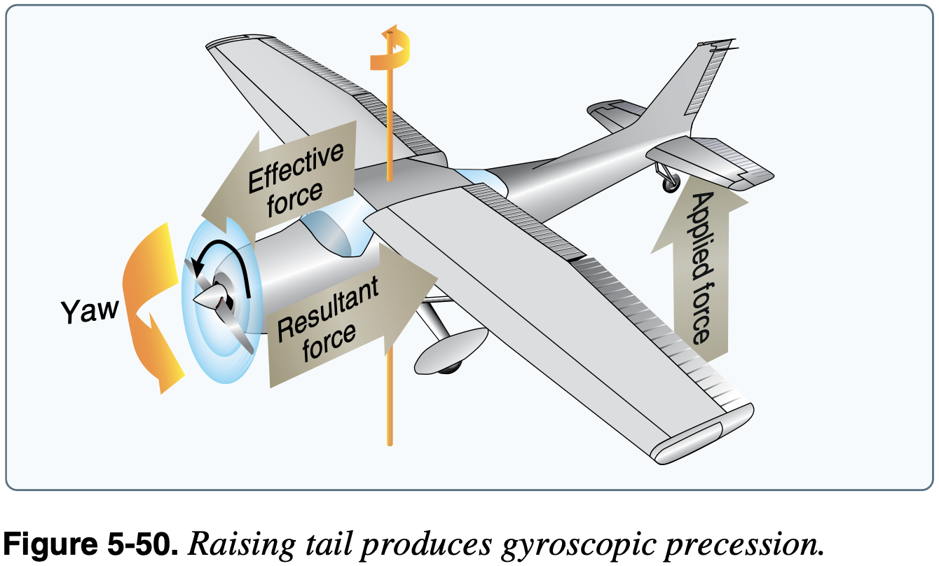
, therefore the angular momentum vector is moving in the direction of - Applying this to an tailwheel aircraft rolling down the runway as it rotates, which is a common instance where this effect can be experienced
is out the nose representing the angular momentum of the spinning propellor, which is spinning clockwise from the pilot's view - A pitch down to raise the tailwheel is a couple
out the left side of the plane - Therefore
is also out of the left side of the plane, meaning the angular momentum is changing towards the left, indicating a left turning tendency
Load Factors
Load Factor
The ratio of an aircraft's lift to it's weight.
The load factor
is given by and is important for two reasons: - It is possible for a pilot to impose a dangerous overload on the aircraft structures.
- An increased load factor increases the stalling speed and makes stalls possible at seemingly safe flight speeds.
Load factor is a convenient value which to specify - it's what the occupants feel, and thus certification standards uses this value on which to set limits.
But since the load factor is dependent on the aircraft weight, the load factors that aircraft are certified for need to meet the requirement at maximum weight.
But this also means that if an aircraft is flown overweight, the same load factor results in greater aerodynamic load than the aircraft is designed to withstand.
14 CFR §23.321 General states:
Compliance with the flight load requirements of this subpart must be shown - at each critical altitude within the range in which the airplane may be expected to operate; at each weight from the design minimum weight to the design maximum weight
The load factors themselves were specified in 14 CFR §23.337 Limit maneuvering load factors. This section of the CFRs was updated on 2017-08-30, and the relevant diff can be viewed here.
The new CFRs for normal category aircraft has changed, but basically says the same thing that the limits must be met under all conditions (including worst case for load factors which is maximum weight)
14 CFR §23.2200 Structural design envelope
The applicant must account for all airplane design and operational parameters that affect structural loads, strength, durability, and aeroelasticity, including: Each critical weight from the airplane empty weight to the maximum weight and the weight and distribution of occupants, payload, and fuel.
14 CFR §23.2210 Structural design loads
Determine the loads required by paragraph (a)(1) of this section at all critical combinations of parameters
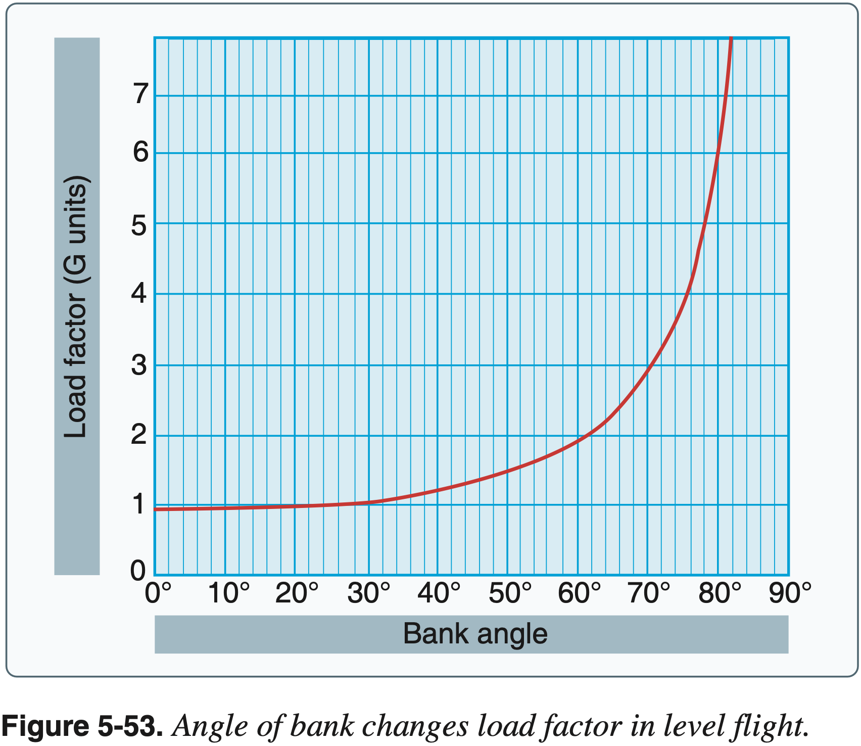
To see how load factor varies with roll angle
So figure 5-53 in PHAK is just a plot of
The maximum speed at which an airplane may be stalled safely is the design maneuvering speed
Maneuvering speed changes proportionally to weight - the lighter the aircraft the slower its maneuvering speed. This is because at lighter weights the angle of attack required for a given flight condition is less, and therefore an abrupt maneuver which can increase the angle of attack to the critical angle of attack will result on a greater increase in load than if the aircraft were heavier and thus starting at larger initial angle of attack.
In the event that maneuvering speed
- Be aware of the aircraft's load factor limit and how to avoid exceeding them
- Stay below
during turbulent conditions - Note the nonlinear increase in load factor with bank, and be mindful of bank angle in steep turns
- Stay below
- Understand how aircraft loading (weight) affects load factor
- And how load factor affects stall speed
- Recognize the importance of operating the aircraft within its limitations
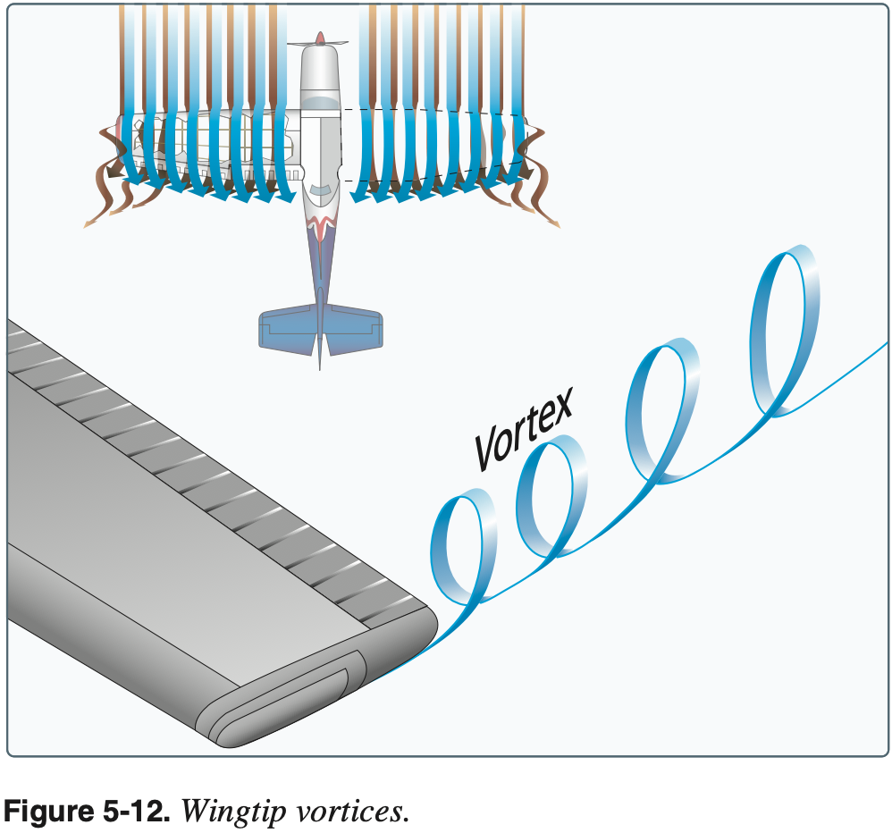
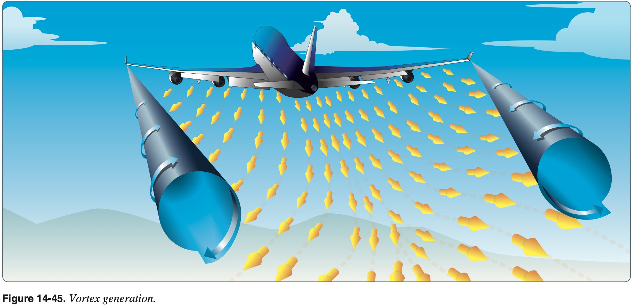
Wingtip Vortices
- Produced as a consequence of a lifting wing
- High pressure below the wing moves around the wingtip to low pressure on top in an inward circular motion
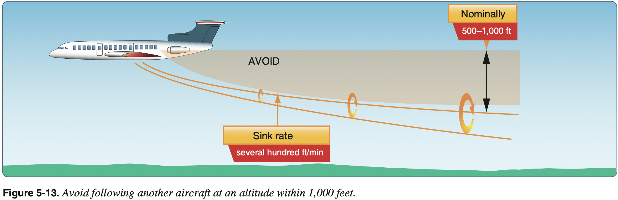
- Wingtip vortices sink behind the aircraft
- Wake turbulence
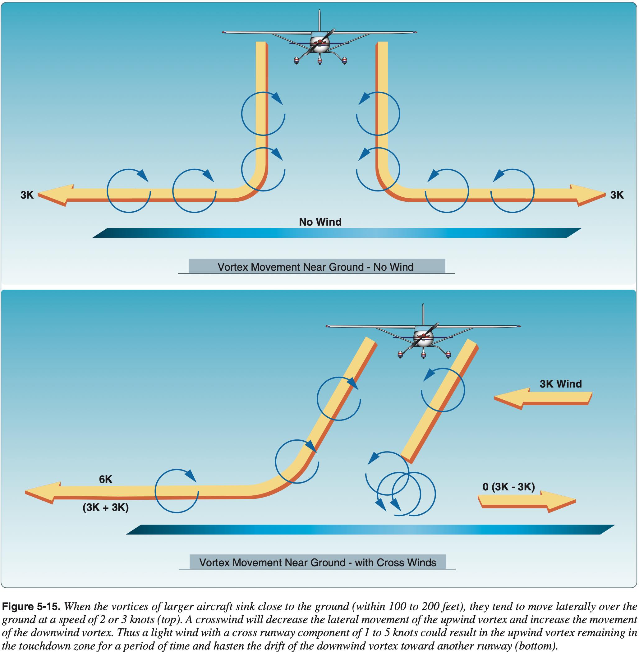
- Lateral vortex movement near the ground about 3 knots
- Light crosswind tendency to keep upwind vortex on runway
- Lateral vortex movement near the ground about 3 knots
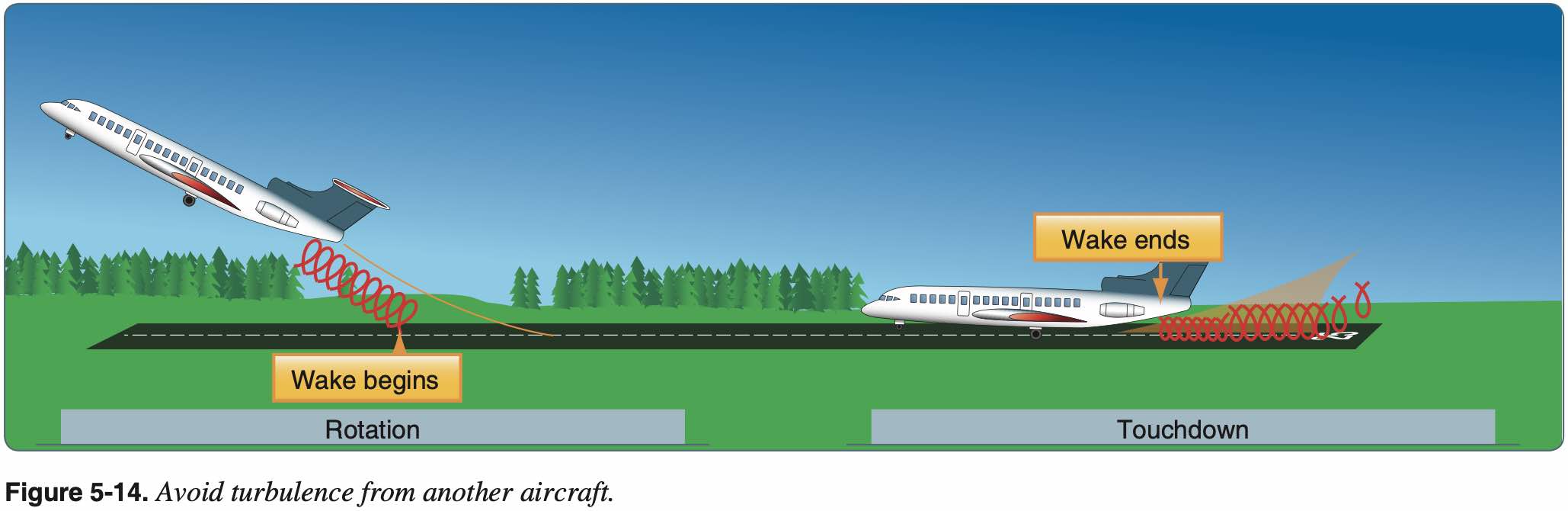
- Avoiding wake turbulence
- Avoid flying through another aircraft's flight path
- Recall radio about Gulfstream following A380 and breaking plates
- Rotate prior to the point at which the preceding aircraft rotated when taking off behind another aircraft
- Waiting 3 minutes for vortices to dissipate also provides a safety
- Avoid following another aircraft on a similar flight path at an altitude within 1,000 feet
- Approach the runway above a preceding aircraft's path when landing behind another aircraft and touch down after the point at which the other aircraft wheels contacted the runway
- Avoid flying through another aircraft's flight path