OEI Performance
This page covers Task P. One Engine Inoperative (OEI) Performance from the FAA-S-ACS-25 Flight Instructor for Airplane Category Airman Certification Standards.
The transition to multi-engine aircraft requires a change in thinking from single-engine aircraft.
- Different mindset - speed is king
- Assume always one engine
- More about maintaiing speed than altitude
- Sacrifice altitude for speed
- Shallower climbout
- Multi considered safer due to redundancy of power and some systems
- Loss of an engine results in 50% loss in power and 80-90% loss of performance
- Also descend shallower too
- More to manage
- For example, starting to descend to KHEF from 2000 feet 8 miles out is reasonable
- Throttle quadrant
- Increase into the knee
- Decrease out of the knee
Performance Charts
- Light twin have no required single-engine performance
- The manufacturer just must publish the value, whether it be a climb or a descent
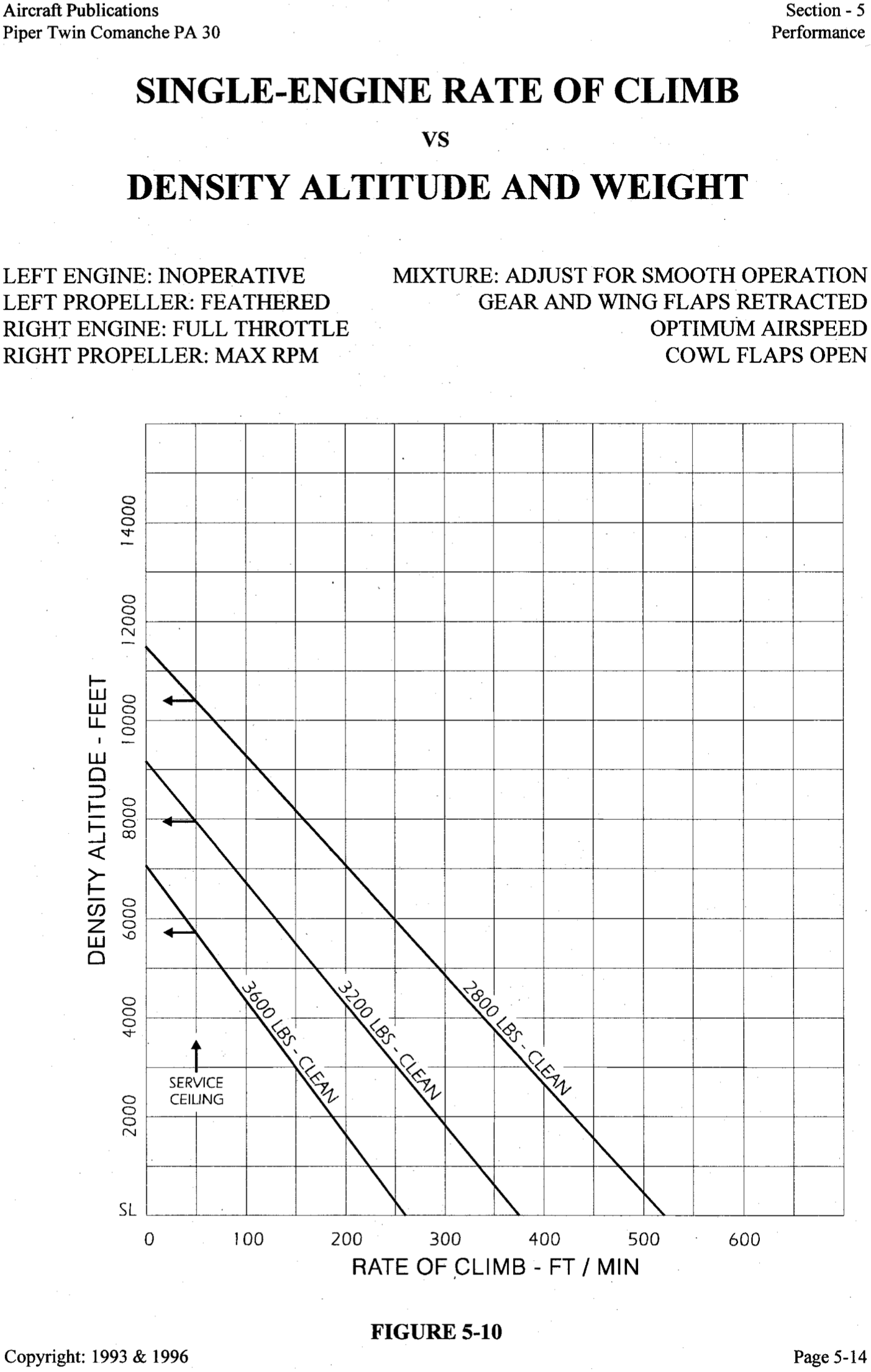
- This is true for twins 6000 lbs or less max weight and
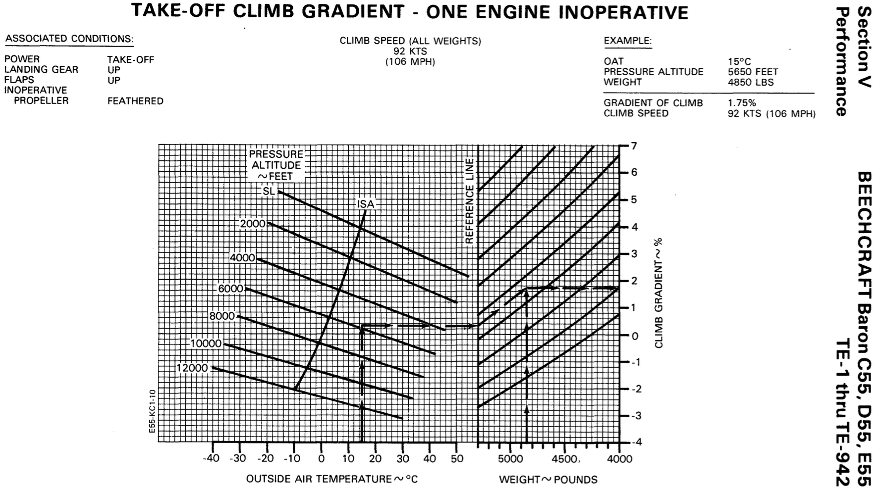
61 kts or less (PA30 is 60) the single engine rate of climb at 5000' MSL must simply be determined - This is not true for the Baron, which has
69 KIAS (see page 2-4 of the POH)
- Starting considerations - which engine to start first
- Engine that starts more easily
- Distance from battery
- Start the engine closer to battery first
- Better being able to hear the second engine start
- Start the engine on pilot side second
- Engine start relative to onboarding passengers
- Start the engine further from onboarding passengers first
- More power in upwind engine when taxiing
- Running both engines up at the same time allows the comparison of the response of each engine
- Be careful on slick surface - may not be able to run up both engines without slipping
- For Twin Comanche accelerate-stop and accelerate-go distances need not be published
- It is a normal category plane not weighing more than 6,000 lbs
- Note: the Twin Comanche was certified under CAR Part 3, so it is those regulations that should be cited
- On takeoff to counteract left turning tendencies can lead with left engine power
- Can also lead with more throttle on the upwind engine in a crosswind
- In no phase of liftoff or takeoff should fly at less than
- Generally: short-field takeoff at
plus 5 knots - In PA-30 short-field takeoff exactly at
(90 mph)
- Generally: short-field takeoff at
Effects of Exceeding Limitations
- TBD
Effects of Atmospheric Conditions on Performance
- TBD
Factors to Consider when Determining Performance
- Basically follow everything in POH/AFM
- Takeoff/landing performance
- Winds
- Surface condition
- Density altitude
- Runway slope
- Cruise performance
- Winds
- Density altitude
- Lean technique
- If there is anything not covered in POH/AFM, use good ADM and act conservatively
- For example, flat spots on tires may decrease landing performance on a wet surface
- Pilot performance
- For example, demonstrated crosswind doesn't mean it's smart for the pilot to do that
- Make sure to do in flight what you have planned for on ground
- For example, if planned for given RPM for fuel burn calculations, not using that power setting in flight will change actual fuel burn versus planned
- From AFH page 13-32 -- Without specific guidance for zero sideslip, a bank of 2 degrees and one-third to one-half ball deflection on the slip/skid indicator toward the operative engine is suggested.
- Generally, weight negatively impacts performance
- Generally, a forward CG decreases performance and increases stability
OEI Aerodynamics
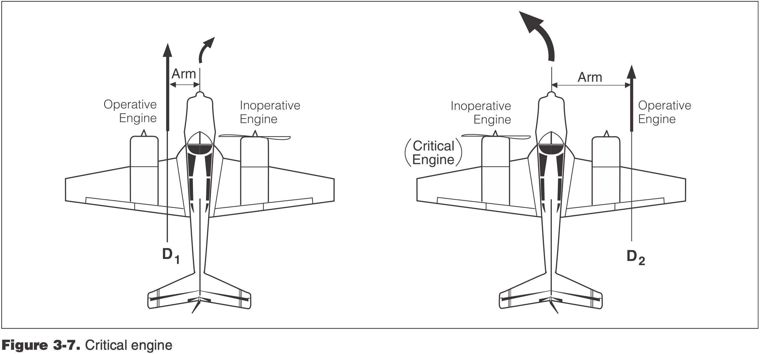
Critical Engine
Critical Engine
The engine which if it fails most adverserly effects aircraft performance and handling. 14 CFR § 1.1
- Determining critical engine (PAST)
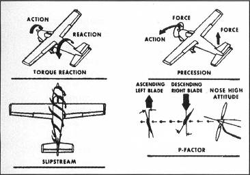
- P - P-factor
- Yaw - due to larger lever arm from center of thrust on the right engine compared to the left
- A - Accelerated slipstream
- Roll - increased lift due to accelerated slipstream is outboard of the right engine and inboard of the left engine, hence a longer moment arm on the right as compared to the left
- Pitch - accelerated slipstream from the left engine has more interaction with the horizontal stabilizer, meaning if the left engine fails there is a larger pitching moment change than if the right engine fails
- S - Spiraling slipstream
- Yaw - The spiraling slipstreams move to the right (due do the accelerated slipstream) and therefore the spiraling slipstream from the left engine interacts more with the vertical stabilizer creating a yawing moment to the left, which is a restoring moment if the right engine is lost. But if the left engine is lost, there is no restoring moment due to the spiraling slipstream from the right engine.
- T - Torque
- Roll - Due to the accelerated slipstream and the rolling moment due to the vertical stabilizer, the aircraft will tend to roll towards the inoperative engine. The torque of the propellor on the aircraft tends to roll the aicraft to the left. Hence, if the right engine fails, the torque effect helps balance the roll, whereas if the left engine fails the torque effect worsens the rolling moment.
- P - P-factor
- When an engine fails the aicraft will tend to:
- Yaw - towards the inoperative engine
- Roll - towards the inoperative engine
- Pitch - down
NOTE
Conventional engines rotate clockwise when viewed from the pilot's position, therefore on most twins the left engine is the critical one.
Minimum Control Speed (
Definition from 14 CFR §23.149 - Minimum control speed (2017)
VMC is the calibrated airspeed at which, when the critical engine is suddenly made inoperative, it is possible to maintain control of the airplane with that engine still inoperative, and thereafter maintain straight flight at the same speed with an angle of bank of not more than 5 degrees.
Minimum Control Speed
Speed below which we cannot maintain directional control if the critical engine quits suddenly.
Minimum control speed (
) - Denoted by a red line on airspeed indicator
- See more below
Page 70
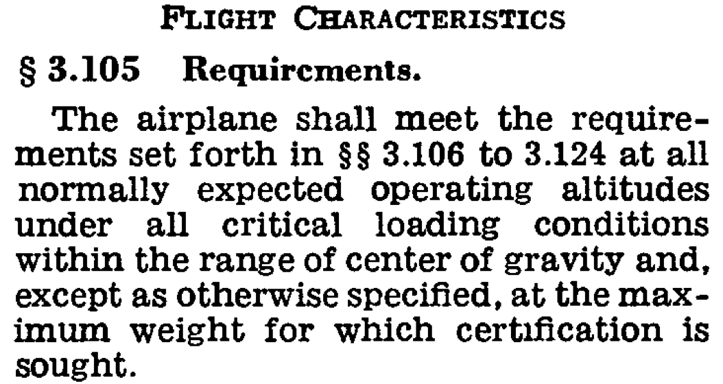
There are variable factors affecting the minimum control speed. Because of this, VMC should represent the highest minimum airspeed normally expected in service.
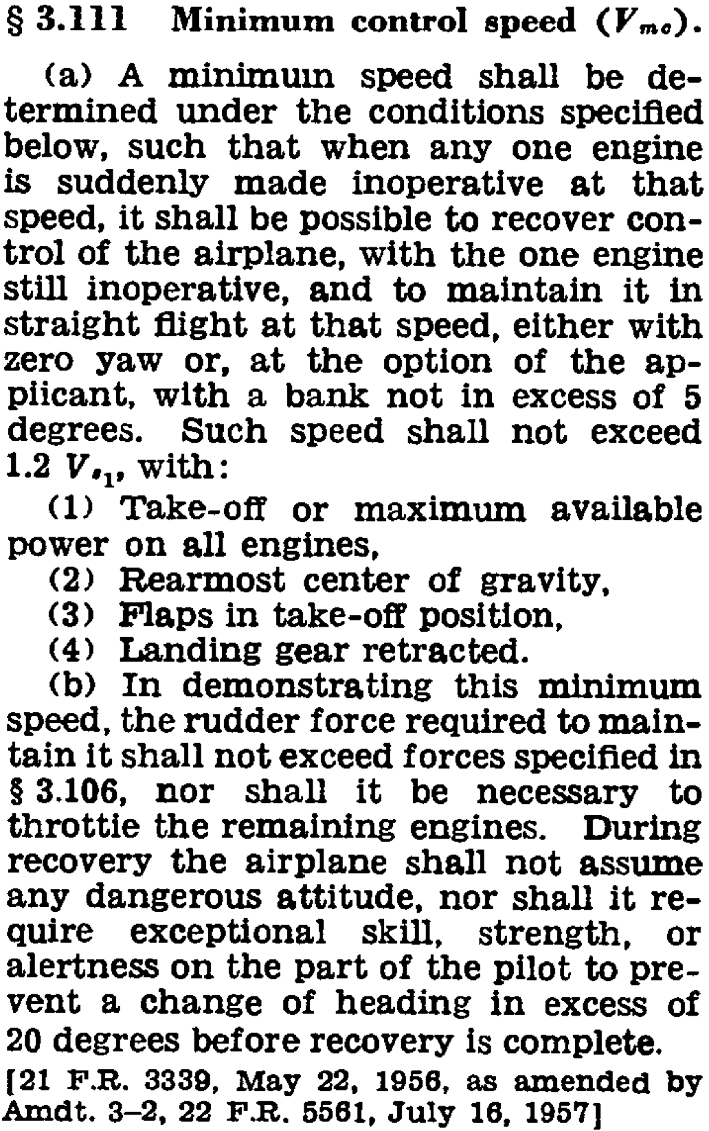
However in old CFR that was current at time of certification 14 CFR PART 3 - Airplane Airworthiness; Normal, Utility, and Acrobatic Categories the regulation seems different in that maximum gross was used.
- Note that the below has changed when Part 23 was rewritten
- The below should be accurate for most light twins that were certified before this change
- Previous Part 23: 14 CFR §23.149 - Minimum control speed (2017)
- Current Part 23: 14 CFR §23.2135 - Controllability
- Went into effect December 30, 2016?
- But eCFR seems to show the old one through 17-August-2017
- The previous Part 23 requirements are explained in FAA-AC-23-8C Flight Test Guide for Certification of Part 23 Airplanes
- See page 70: 4. §23.149 Minimum Control Speed.
- Sample comparison page of old versus new CFR: 14 CFR §23.149(b)(4) (2017)
- Comparison: 14 CFR §23.149 - Minimum control speed (2017)
- Old CFR from the 1960s: 14 CFR PART 3 - Airplane Airworthiness; Normal, Utility, and Acrobatic Categories
- Determined with (COMBATS)
C - Critical engine failed and windmilling
- Failed engine propeller full forward in the high RPM setting
- 14 CFR §23.149(b)(5) (2017)
O - Operating engine at takeoff power
- Lowering power decreases
- Less moment due to assymetric thrust that needs to be offset by rudder
- 14 CFR §23.149(b)(1) (2017)
- Lowering power decreases
M - Most unfavorable weight (light)
- Lighter weight is unfavorable and increases
- This is because the bank effect at light weight is reduced, either in that a bank up to the maximum of 5° is not sufficient to achieve zero sideslip, or that in any case more bank is required at a lighter weight, hence less vertical lift. It is this bank effect that is mentioned in FAA-AC-23-8C. The argument of weight relating to moment of inertia is not clear to me, but the process for determining
as described in FAA-AC-23-8C does discuss using the highest of the static and dynamically determined values in the AFM.
- This is because the bank effect at light weight is reduced, either in that a bank up to the maximum of 5° is not sufficient to achieve zero sideslip, or that in any case more bank is required at a lighter weight, hence less vertical lift. It is this bank effect that is mentioned in FAA-AC-23-8C. The argument of weight relating to moment of inertia is not clear to me, but the process for determining
- See 14 CFR §23.149(b) (2017)
- Lighter weight is unfavorable and increases
B - Bank up to 5° to raise the dead engine
- 2-3° is usually enough to attain zero sideslip
- Banking beyond the zero-sideslip value can decrease
but also decreases performance - A slight bank decreases
due to the reduction in sideslip, which otherwise during equilibrium wings-level flight creates an additional adverse yawing moment due to weathercock stability. See Controlling Multi-Engine Airplanes after Engine Failure by Harry Horlings. - 14 CFR §23.149(a) (2017)
A - Most unfavorable CG (aft)
- Aft CG is unfavorable and increases
- Forward CG decreases
- Longer moment arm between rudder and CG
- See 14 CFR §23.149(b) (2017)
- Aft CG is unfavorable and increases
T - Takeoff configuration
- Trimmed for takeoff
- Flaps in takeoff position
- More flaps, gear, cowl flaps all decrease
- More flaps, gear, cowl flaps all decrease
- Gear up
- Cowl flaps in takeoff position
- Props forward
- Out of ground effect
- Ground effect decreases
- Ground effect decreases
S - Standard day
Sea-level
See FAA-AC-23-8C page 74
The
resulting from this extrapolation to sea level is the one entered into the AFM and marked on the airspeed indicator.
Up to 150 lb of rudder force required
is established based on the certification requirements above, but changes with changing aircraft configuration and flight condition - If we are near
and slowing, recover by decreasing power on remaining engine and decrease pitch decreases with altitude because power decreases - But aerodynamic force of rudder to counteract yawing moment from a single engine is also less, what is the functional relationship with aero force versus altitude as compared with thrust versus altitude?
- By 14 CFR §23.149(e) (2017) and 14 CFR §23.149(a) (2017) the "maintaining directional control" is defined that the test pilot must be able to
- Stop the turn within 20 degrees using max rudder and no more than 5 degree of bank
- Maintain straight flight with no more than 5 degrees of bank
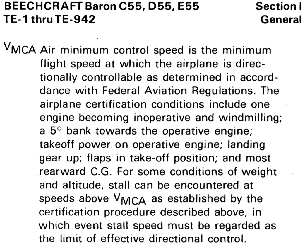
- The title page of the POH states that the C55 Baron was certified under CAR 3.
C55 Baron COMBATS
- C - Critical engine failed
- CAR3 doesn't seem to explicitly state prop full forward, although the newwer 14 CFR §23.149 (2017) does
- Also that the prop be windmilling seems to not be specified in CAR 3, but the Baron E55 POH, under the definition of VMCA, says that CAR 3 does specify with the prop windmilling.
- O - Operating engine at takeoff power
- M - Max gross weight
- The later 14 CFR §23.149 (2017) specified most unfavorable weight
- B - Bank up to 5° to raise the dead engine
- A - Aftmost CG
- T - Takeoff configuration
- Gear up
- Flaps up
- S - Standard day
- 1 - 150 lb rudder force max
- C - Critical engine failed
The later 14 CFR §23.149 (2017) specifies out of ground effect, but CAR3 does not seem to
FAA-H-8083-3C Airplane Flying Handbook Chapter 13: Transition to Multiengine Airplanes says the following
A knowledgeable and competent multiengine pilot understands that
is not a fixed airspeed under all conditions. is a fixed airspeed only for the very specific set of circumstances under which it was determined during aircraft certification. In reality, varies with a variety of factors as outlined below. The noted in practice and demonstration, or in actual OEI operation, could be less or even greater than the published value, depending on conditions and pilot technique. Increased weight decreases
There may be an arguement here about the corresponding increased moment of inertia in the dynamic case, although this doesn't really apply to the static case
FAA-AC-23-8C Flight Test Guide for Certification of Part 23 Airplanes says the following
should be determined at the most adverse weight. Minimum practical test weight is usually the most critical because the beneficial effect of banking into the operating engine is minimized. This seems to imply that this is only true of the 5° limit on bank angle is imposed - if in practice we need not respect that limit - then I don't see how weight has that strong of an effect of
.
Addition of bank offsets horizontal aerodynamic force from rudder to achieve lower drag by zero-sideslip flight
See Section 4 23.149 Minimum Control Speed on Page 70 of FAA-AC-23-8C Flight Test Guide for Certification of Part 23 Airplanes
Dynamic vs Static
The discussion of dynamic versus static
FAA-AC-23-8C Flight Test Guide for Certification of Part 23 Airplanes
Appendix 3. Static Minimum Control Speed Extrapolation to Sea Level
The purpose of this appendix is to identify one method of extrapolating minimum control speeds (
) observed during flight tests, to sea level, standard temperature conditions. There is a geometric relationship between the yawing moment about the c.g. caused by the operating engine, and the rudder deflection necessary to offset this tendency and cause an equilibrium. 14 CFR §23.149(a) (2017) requires the following.
is the calibrated airspeed at which, when the critical engine is suddenly made inoperative FAA-AC-23-8C Flight Test Guide for Certification of Part 23 Airplanes describes the static
testing process. Gradually reduce airspeed until it is no longer possible to prevent heading changes with maximum use of the directional and near maximum use of the lateral controls, or the limit control forces have been reached. No changes in lateral or directional trim should be accomplished during the speed reduction.
It then requires the applicant to perform dynamic
testing as follows. After determining the critical engine static
, and at some speed above static , make a series of engine cuts (using the mixture control or idle cutoff control) dynamically while gradually working speed back toward the static speed. It goes on to describe the requirements of such dynamic
testing including the heading deviation no more than 20° heading change. Frequently, the dynamic
demonstration will indicate a lower than is obtained from static runs. This may be because the inoperative engine, during spooldown, may provide net thrust or control force peaks that exceed limit values for a short period and go undetected, or, due to high yaw and pitch angles and rates, the indicated airspeed values are erroneous. Because of the multi-variable nature of the dynamic demonstration, the AFM value should represent the highest of the static or dynamic test data, corrected to critical conditions.
Effects of Bank Angle on
- There seems to be a lot of incorrect explanations around as to why a bank angle to raise the dead engine is good.
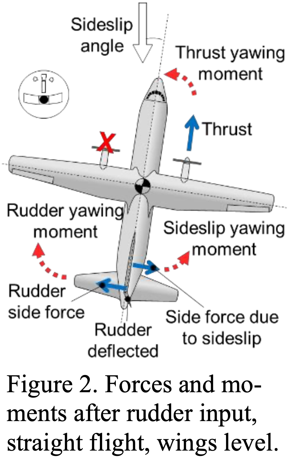
- The best reference I found is Controlling Multi-Engine Airplanes after Engine Failure with better diagrams than in the FAA handbooks.
- To explain it concisely, it is easiest to talk about the forces in the aircraft body-fixed axes.
- Without a bank, in steady-level flight, the aircraft is sideslipping.
- The weathercock stability due to this sideslip produces a moment in the same direction as the operative engine, making a larger moment that the rudder needs to counteract, and therefore requiring a higher speed to achieve this moment.
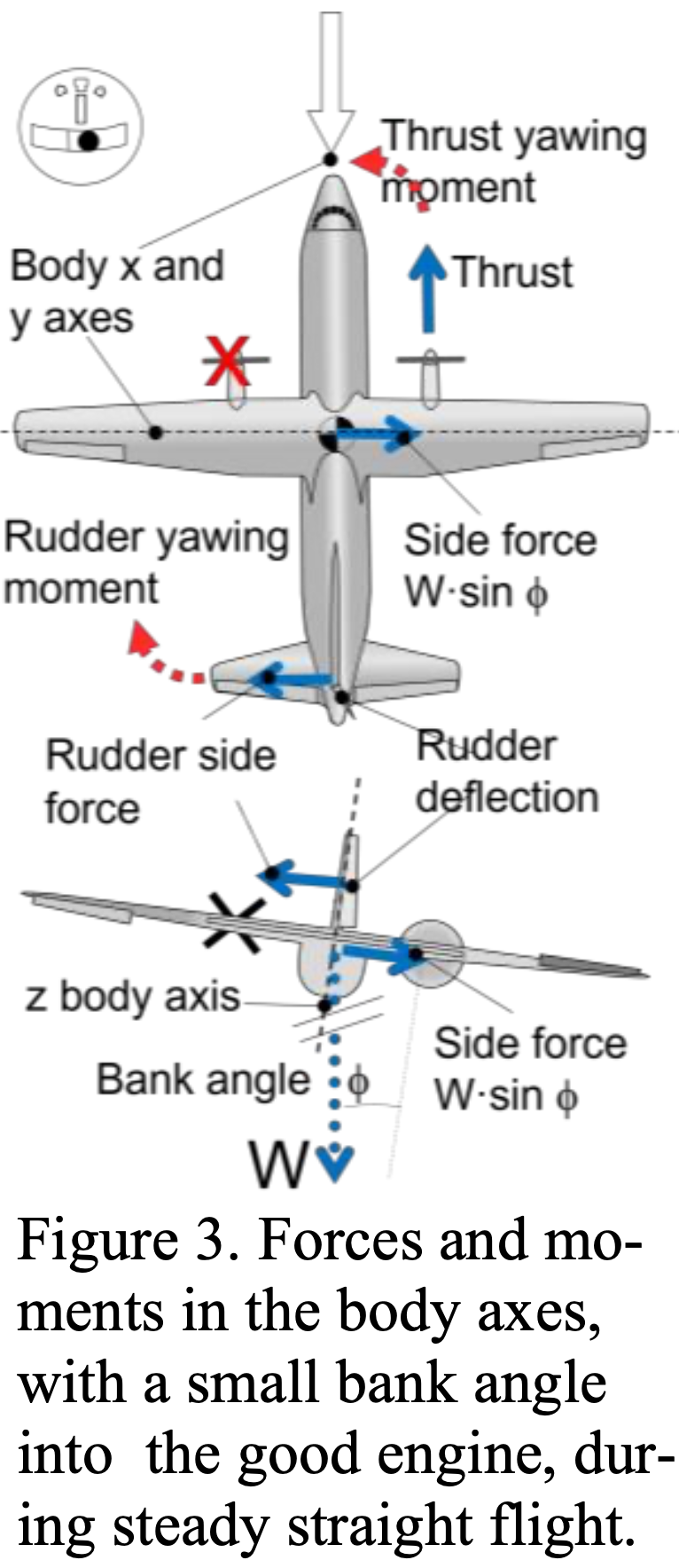
- By banking slightly, a component of gravity acts along the body y-axis preventing sideslip.
- This means the moment the rudder must provide is lower, and therefore at maximum rudder deflection a lower airspeed can be used.
Part 23 and
The rules that pertain to an airplane depend upon the rules in effect during type certification and do not depend on the production year after certification.
The determination of
as described above was changed on 30-August-2017. - This ammendment was 81 FR 96689
The article AOPA Understanding Part 23 Rewrite has a bit of information
14 CFR §23.149 - Minimum control speed (2017) provides the previous rules for certification which is applicable to planes certified under the older rules
14 CFR §23.2135 - Controllability provides the new rules for certification
Given the recency of the change, most of the light twins used for training purposes will have been certified under the old rules, so that is probably best considered as the "primary" reference
FAA-H-8083-3C Airplane Flying Handbook Chapter 13: Transition to Multiengine Airplanes says the following, where emphasis has been added.
The following bullets describe the way several factors affect
speed for those multiengine airplanes often used during training, which were certified in accordance with historical 14 CFR part 23, section 23.149.
Appendix
Increased weight decreases
There may be an arguement here about the corresponding increased moment of inertia in the dynamic case, although this doesn't really apply to the static case
FAA-AC-23-8C Flight Test Guide for Certification of Part 23 Airplanes says the following
should be determined at the most adverse weight. Minimum practical test weight is usually the most critical because the beneficial effect of banking into the operating engine is minimized. This seems to imply that this is only true of the 5° limit on bank angle is imposed - if in practice we need not respect that limit - then I don't see how weight has that strong of an effect of
.
Addition of bank offsets horizontal aerodynamic force from rudder to achieve lower drag by zero-sideslip flight
See Section 4 23.149 Minimum Control Speed on Page 70 of FAA-AC-23-8C Flight Test Guide for Certification of Part 23 Airplanes
Single Engine Aerodynamics Overview
NOTE
Loss of an engine in a twin reduces thrust by 50%, but decreases climb performance by 80-90%.
- Climb rate is dependent on excess power which is why when losing half the aircraft's thrust results in less than half the normal climb rate
- Climb angle is dependent on excess thrust
- Recall
where is power, is thrust, and is velocity - Rolling tendency occurs when an engine fails due to lift distribution being higher on wing with operative engine
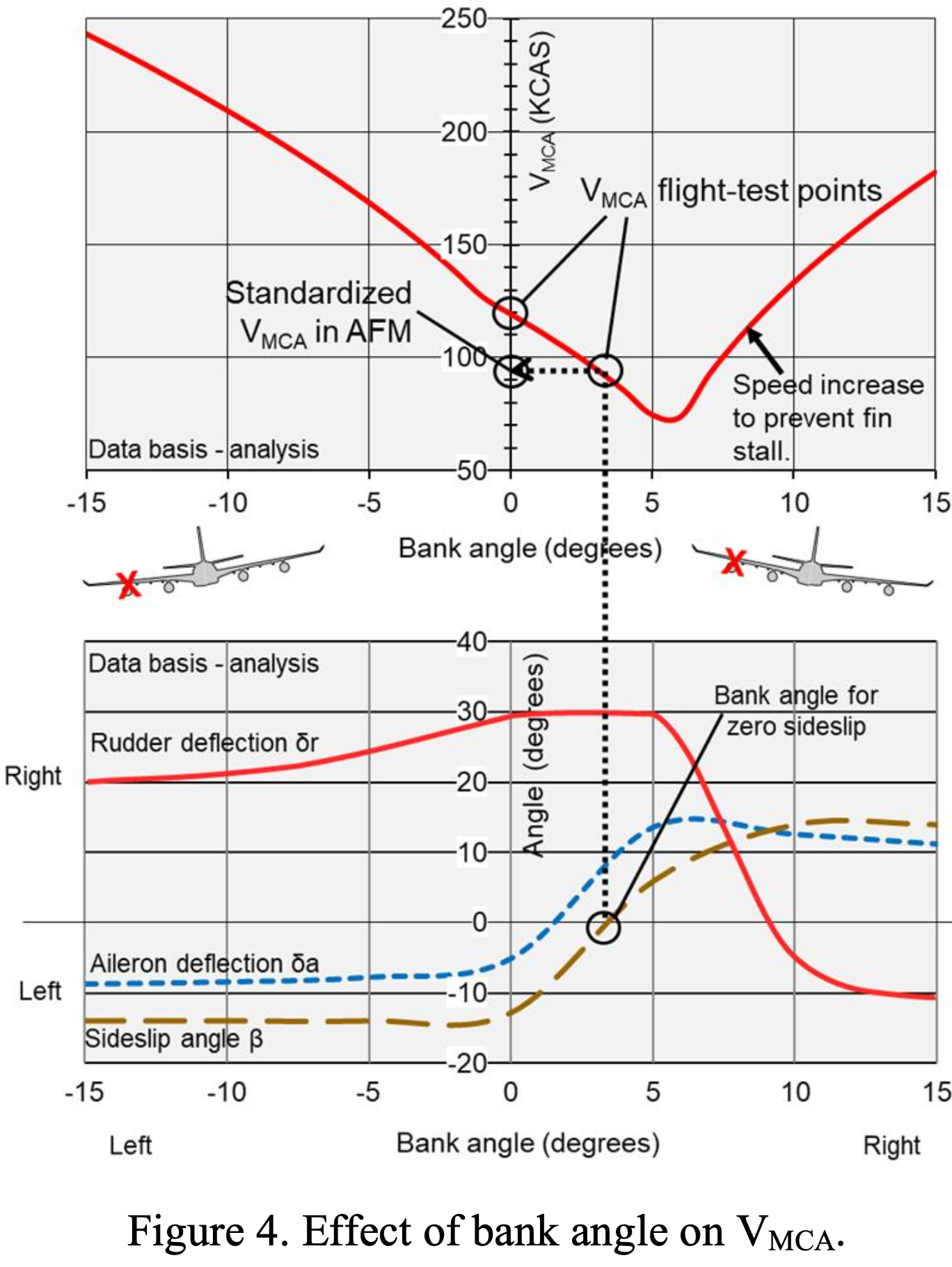
- Can use more than 5° bank to improve directional control
- Greater bank angle = lower
- This reduces performance though because of increased drag
- Greater bank angle = lower
- After directional control is established reduce the bank to 5°
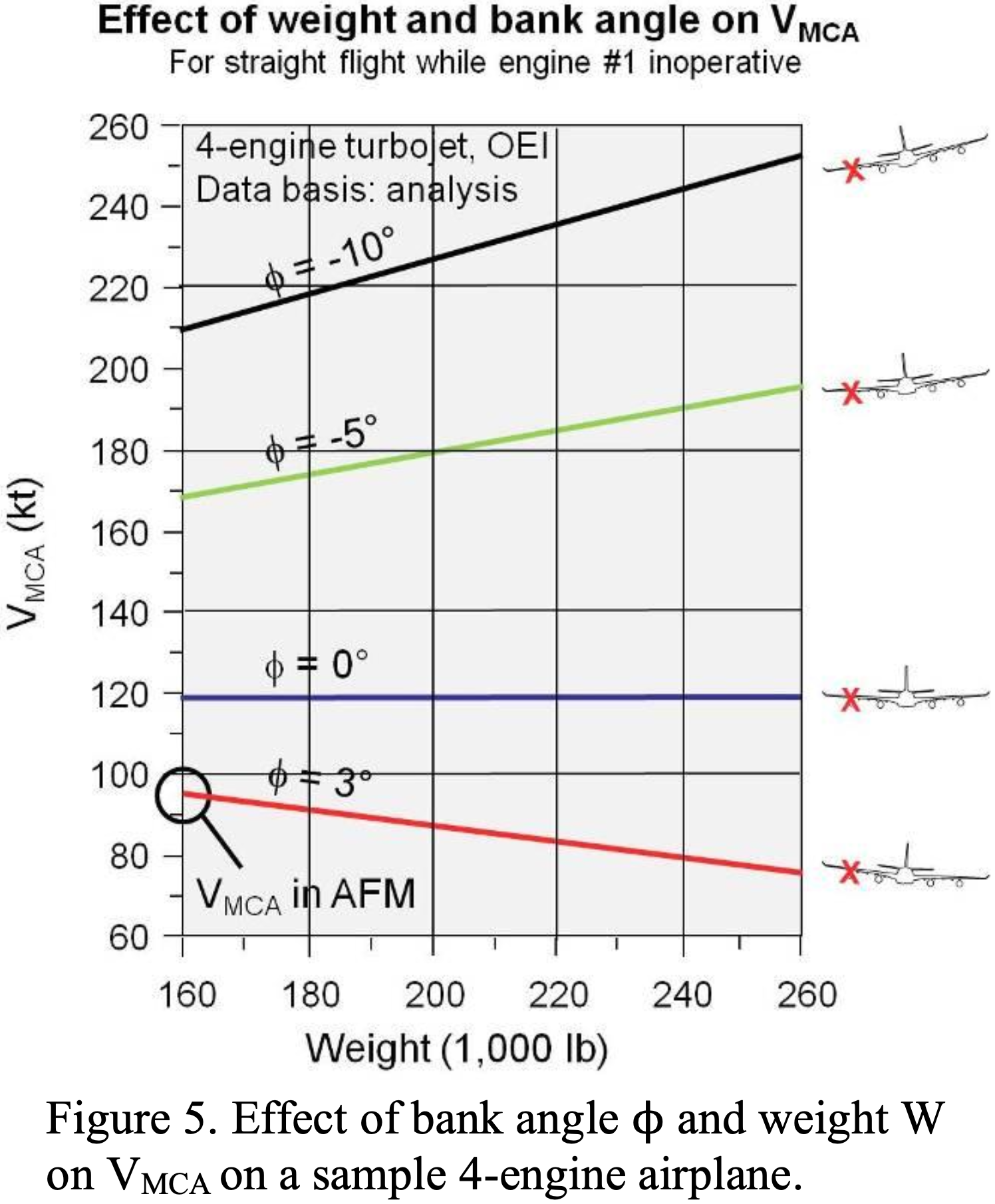
- Increase in weight also decreases
- Feathering dead engine reduces
can increase by as much as 20 knots with wings level - When practicing
demonstration - Sufficiant altitude (Minumum 3,000' AGL in PA-30, 5,000' in B55)
- Use
safe single engine speed - 97 mph for PA-30 - Gear up
- Flaps and cowl flaps in takeoff setting
- Trim for takeoff
- Prop full forward, throttle to takeoff power
- Reduce throttle on critical engine to idle
- Raise the dead
- Slowly pitch to single engine climb attitude
- Apply rudder to maintain heading until full rudder deflection applied
- Rudder deflection can be artificially limited with a foot to ensure simulated
occurs sufficiently above stall speed
- Rudder deflection can be artificially limited with a foot to ensure simulated
- Recovery
- Reduce power on good engine
- Pitch down to increase airspeed and increase angle of attack
- Pitch for
- If prop loses oil pressure it will feather by default
- The impacts of the loss of an engine can be separated into two categories
- Loss of performance
- Loss of control
Multi-engine Airspeed Definitions
- speed below which directional control cannot be maintained - safe single engine speed, minimum speed to use during OEI training - best angle of climb with OEI - best rate of climb with OEI - rotation speed - unless otherwise published should be at least plus 5 knots
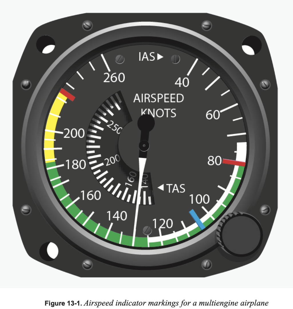
Single engine best rate of climb (
- Denoted by blue line on airspeed indicator
- Previous Part 23:
- Current Part 23: 14 CFR §23.2120 - Climb requirements
- For planes 6,0000 lb or less and
of 61 knots or less (like the PA-30), single-engine climb performance must simply be determined - For planes 6,0000 lb or more and/or
of more than 61 knots (like the C55 Baron) single-engine climb performance must be at least 0.027
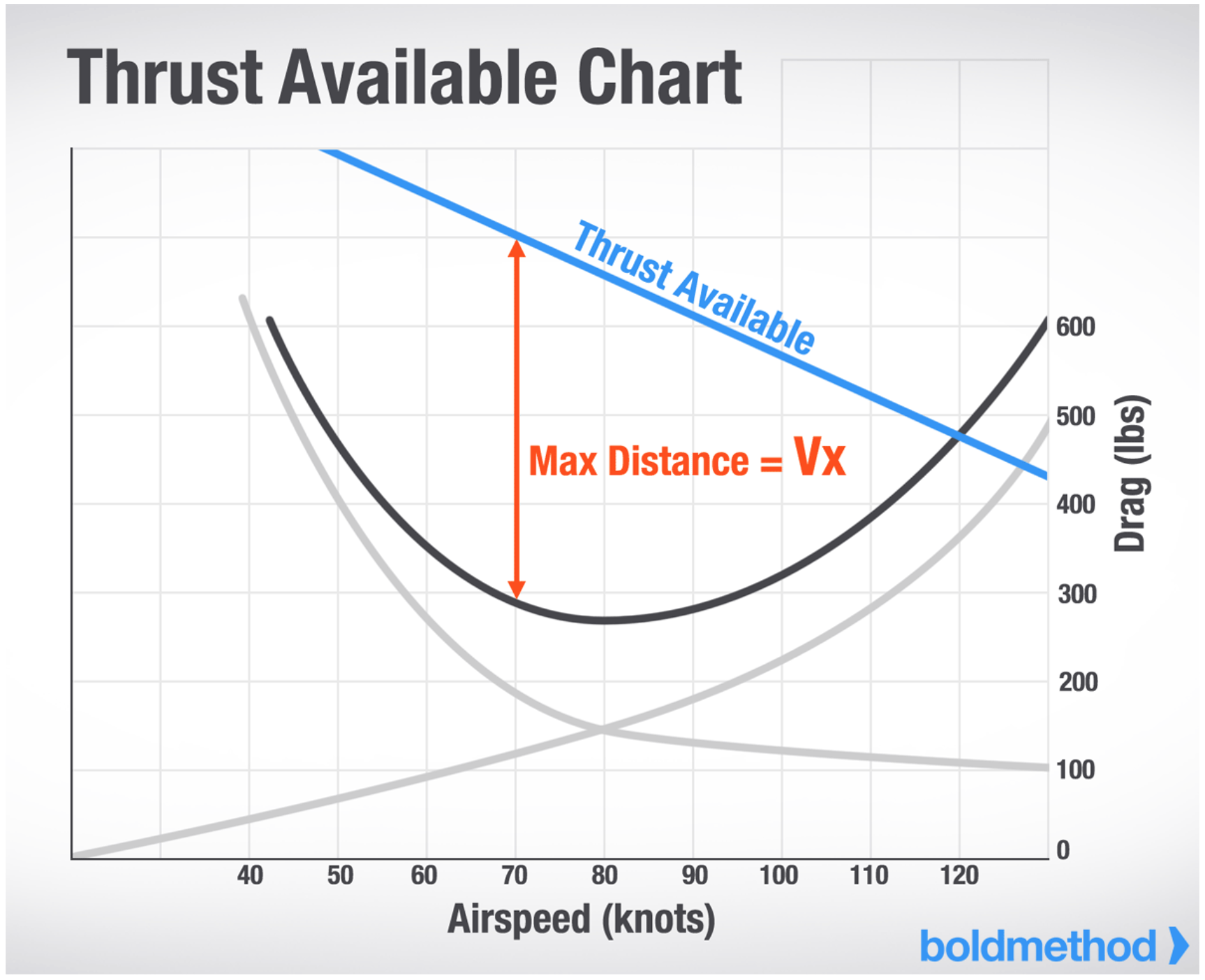
Comparison of
- Total drag is also known as thrust required - the amount of thrust you need to stay level at a specific airspeed.
- Your propellor can generate the most thrust at a slow speed. Why? Because it's at a high angle of attack. As your airspeed increases, the propellor's angle of attack decreases, and it can generate less thrust.
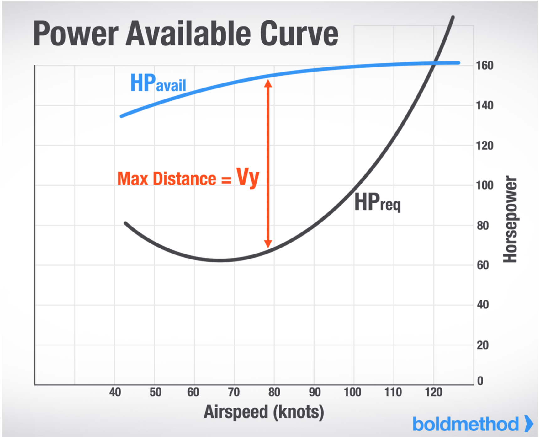
is when most thrust is available. Basically, for want to climb slowly, to minimize distance traveled over the ground. is the speed where you have the biggest difference between power required and power available. - For a piston plane, the angle of climb depends on excess thrust.
Derivation of
The following are in the aircraft body axes frame.
From \eqref{eq.xdir}:
The maximum flight path angle is therefore given by the following
Thus
Maximizing
Thus
Comparing Best Angle and Rate of Climb AEO vs. OEI
- Assume a fixed altitude and atmospheric conditions, and evaluate the following
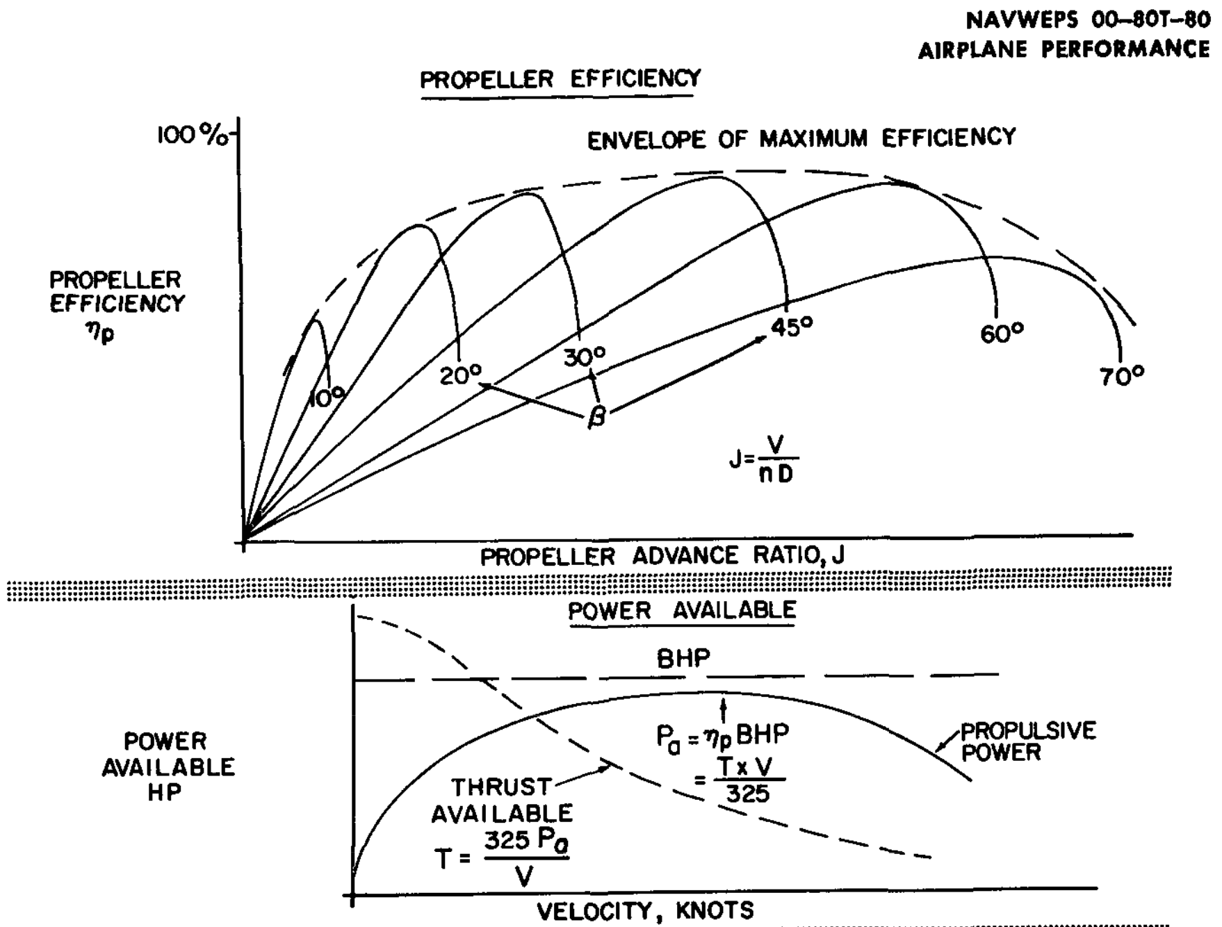
- Start with fixed engine BHP as a function of airspeed
- Take an propellor efficiency curve which is 0 at 0 KIAS and is concave down
- Propulsive efficiency
- Propulsive efficiency
- This gives a propulsive power curve of the same shape (as the efficiency curve is multiplied by a constant)
- In NAVAIR 00-80T-80 Aerodynamics for Naval Aviators
is used for propulsive power available - Assume as well that the peak propellor efficiency is around cruise airspeed
- Then thrust is given by the following
- To see how thrust then decreases with airspeed, we can assume a (concave down) quadratic form in
- When dividing such a quadratic form in
by , the result is linear with a negative slope
- When dividing such a quadratic form in
- With this, when power is halved (assuming one of two engines is inoperative), given it is increasing over the airspeed range of maximum excess power, this halving results in the available power curve flattening and therefore
being less than . - Similarly, given thrust is increasing over this range, the same flattening that occurs when it is halved makes
greater than .
Reasons for loss of directional control
- Unable to balance moments caused by only one operative engine
- This is largely related to a decreased airspeed which reduces rudder effectiveness
- Other factors include
- Failing to follow the correct procedures
- Setting correct aircraft configuration
- Flying the right airspeed and bank angle
- Inattention due to distraction
- Failing to follow the correct procedures
- Must stay above
and in most situations if possible
More Stuff
- Indications of loss of directional control
- After rudder is fully deflect and a yaw occurs
- Importance of maintaining the proper pitch and bank attitude, and the proper coordination of controls
- Correct pitch and bank lowers
- Coordination during OEI does not mean centering the ball
- Proper coordination of the flight controls helps ensure that
is low and performance is good
- Correct pitch and bank lowers
- Loss of directional control recovery procedures
- The initial loss of direction control will happen during the maneuver
- Unless indications of impending stall are experienced first, in which case recovery will be initiated
- The recovery procedure requires
- Reducing the overwhelming moment on the plane due to a single operative engine
- Increasing airspeed to get above
, targeting
- To perform the recovery
- Reduce the power on the operative engine to idle
- Lower the nose to increase airspeed
- After above
increase the throttle of the operative engine to full and climb away at
- The initial loss of direction control will happen during the maneuver
- Engine failure during takeoff including planning, decisions, and single-engine operations.
- The plan for what to do should the engine failure at different points during the rollout, takeoff, and climbout should be briefed ahead of time
- Performance data should be calculated to be able to form the correct plan
- Environmental effects also must factor into the engine failure plan
- General recommendation from AFH page 13-16 is raise the gear no later than after reaching
airspeed on takeoff
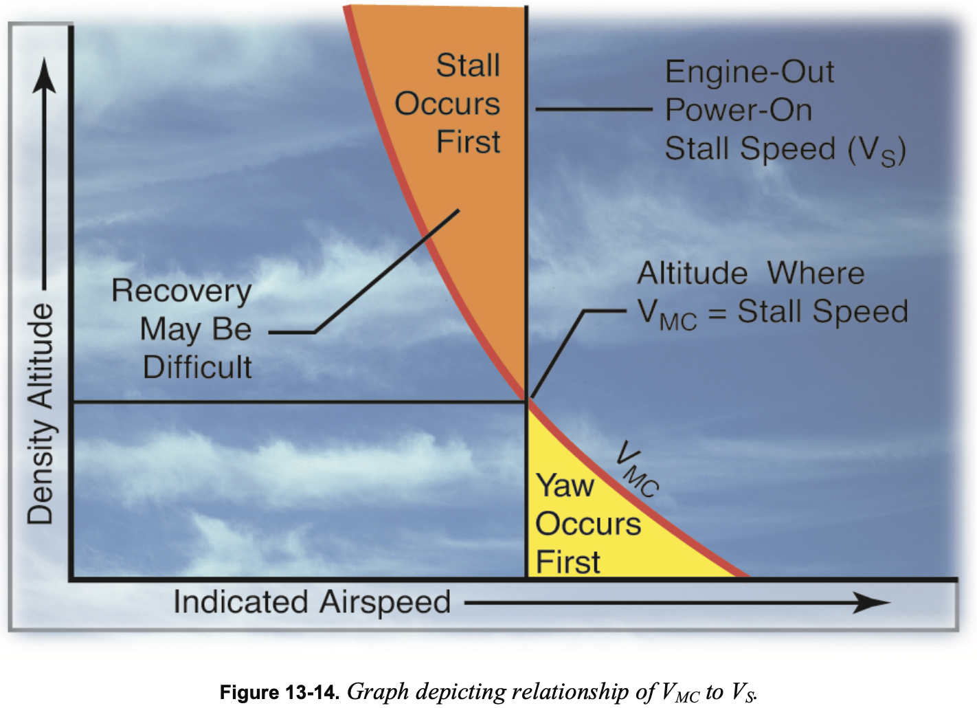
Relationship Between
- As the aircraft is slowing during a VMC demonstration, it is approaching one of two possible things happening
- Stall
- Loss of control
- See the figure below,
decreases with altitude, stall speed remains the same - When plotted against IAS
Determining Best Course of Action After Engine Failure
- TBD