Flight Controls and Systems
This page covers Task E. Aircraft Flight Controls and Operation of Systems from the FAA-S-ACS-25 Flight Instructor for Airplane Category Airman Certification Standards.
Primary flight controls
Primary Flight Controls
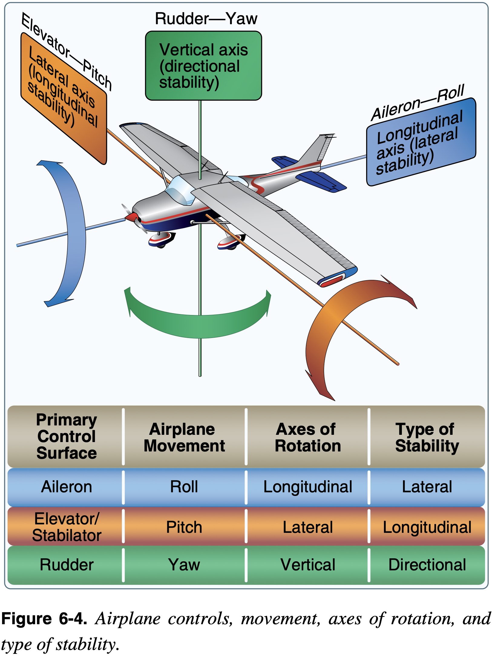
Control the surfaces to create the moments to rotate an aircraft about its three axes of rotation.
- Airplanes are maneuvered by changing the direction of lift.
- There are three axes about which moments are applied and the aircraft rotates.
- Different primary flight control surfaces
- Elevator
- Aileron
- Rudder
- More
- V-tail
- Stabilator
- Different primary flight control surfaces
Adverse Moments
- Control surfaces intended to induce moments about one particular axis often also induce moments about other axes as well
- For example, with the vertical stabilizer being offset above the aircraft's longitudinal access, deflection of the rudder, while it primarily induces a yawing moment also induces a rolling moment
- Adverse yaw is the term used to describe the yawing moment that typically accompanies deflection of the ailerons
- For exampe, to roll to the right the left aileron must deflect downwards
- This downward deflection, used to increase the left on the left wing, also creates additional drag and therefor a yawing moment to the right, opposite the direction of turn
- This is why coordination of ailerons and rudders is important
- Differential ailerons are a design choice used to reduce this effect by reducing the downward aileron deflection relative to the upward deflection.
- The Piper Archer uses differential ailerons
Secondary Flight Controls
Secondary Flight Controls
Those which are not considered primary and are used to change the aircraft's performance, or reduce the amount of control a pilot has to use.
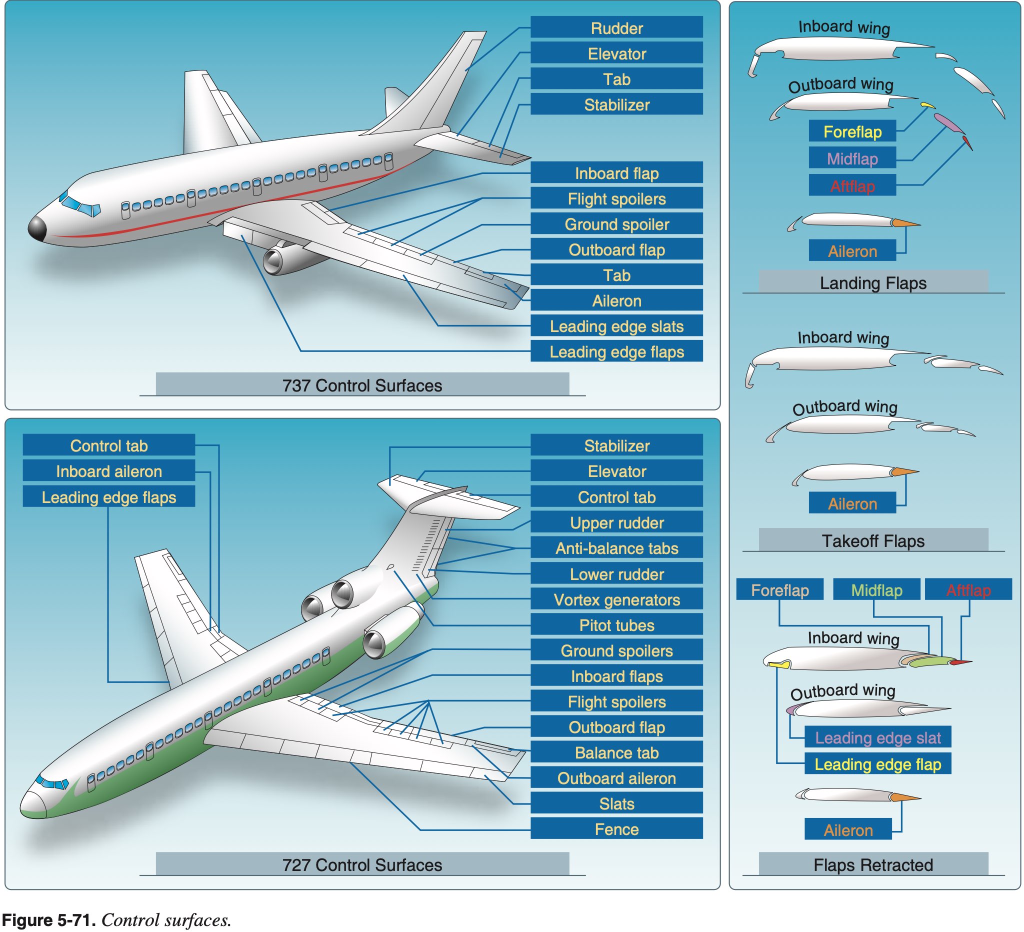
- They may consist of wing flaps, leading edge devices, spoilers, and trim systems.
- Flaps
- Change the relationship between lift and drag
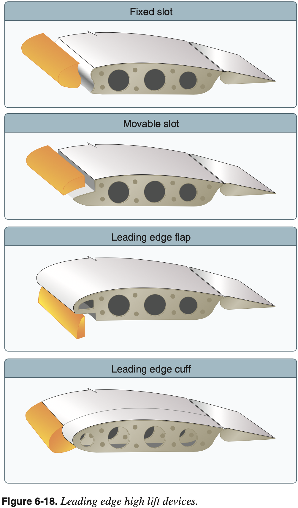
- Slots / Slats
- Located on the leading edge
- Allows higher angles of attack by redirecting airflow from under the wing to the top delaying separation
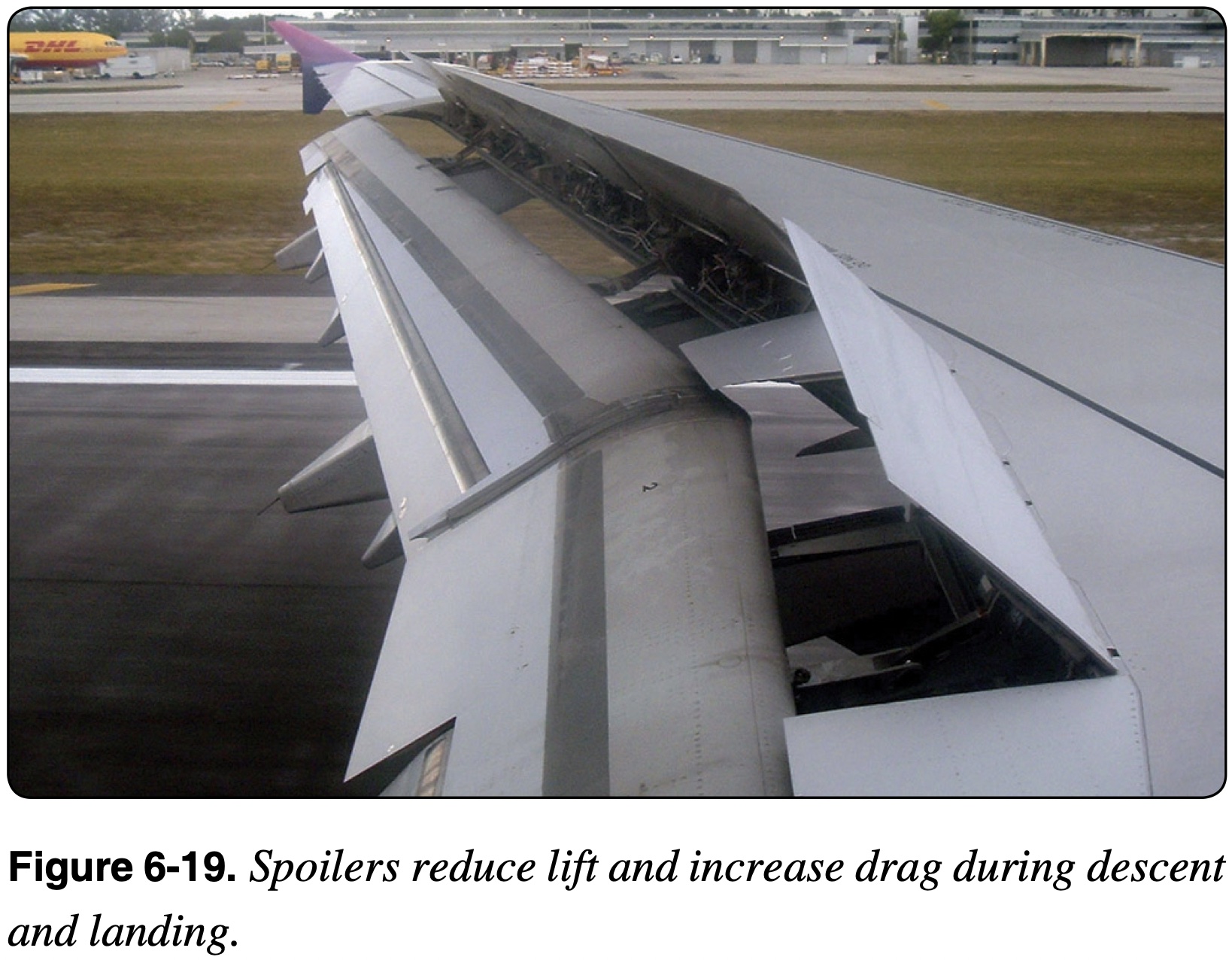
- Spoilers
- Reduce lift and increase drag
Flaps
NOTE
At the most fundamental level, flaps change the shape of the wing with the primary goal of changing the relationship between lift and drag.
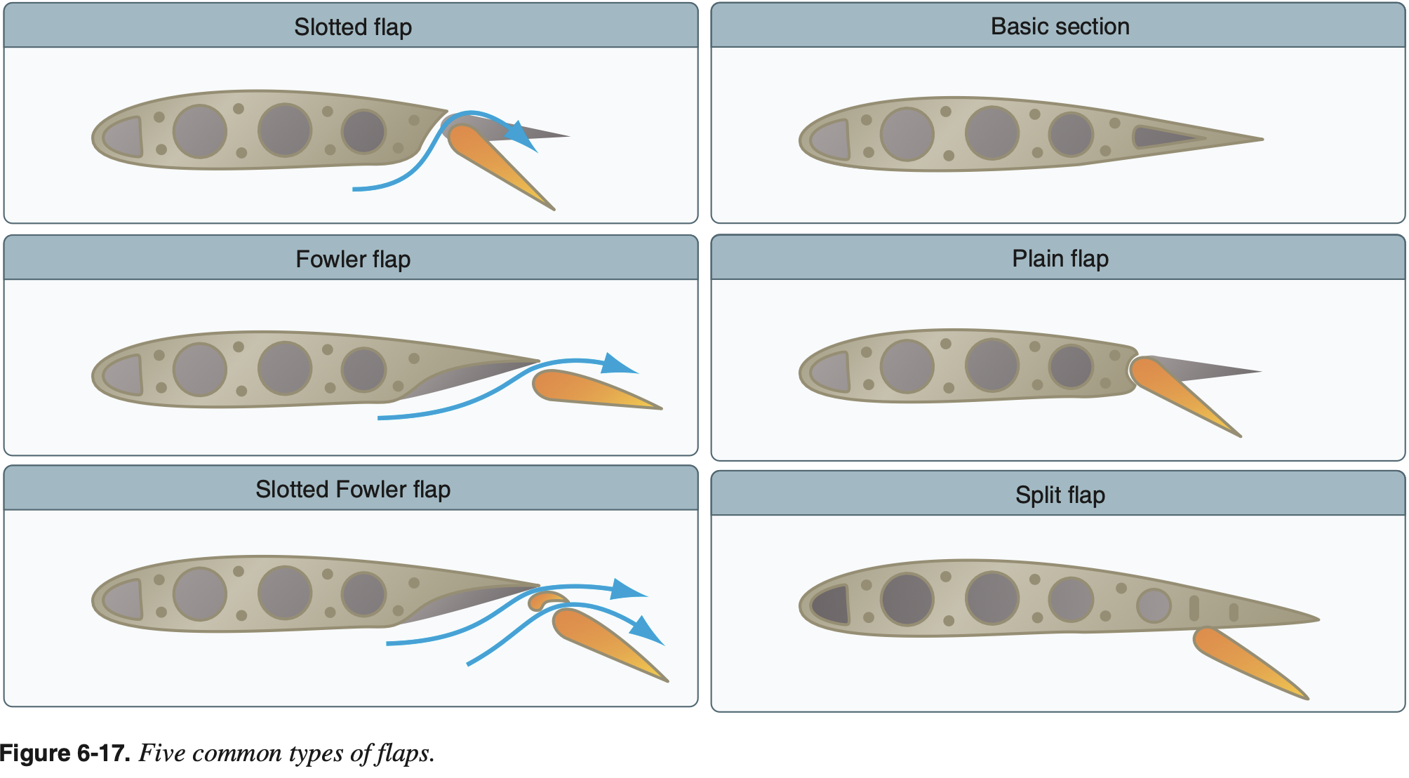
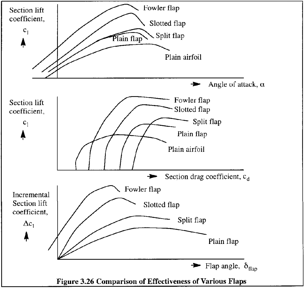
Flap Types
- Plain Flaps
- Characterized by a hinging a rearward section of an airfoil about a point within the airfoils contour
- Main effect is an increase effective camber of the airfoil
- Increases lift coefficient at zero angle of attack and reduces stall angle of attack
- Split Flaps
- Characterized by hinging only the lower portion of a rearward section of an airfoil
- Similar aerodynamically to plain flaps but with better high angle of attack performance due to less separation on the upper surface
- Creates least change in pitching moment
- Slotted Flaps
- Characterized by slots between the flap and main airfoil section when the flap is deflected
- Flap rotates about a point outside of the airfoils contour creating a gap, or a slot, through which air can flow
- Uses high energy air beneath the airfoil to delay separation over the flap
- Fowler Flaps
- Charaterized by a rearward translation of the flap resulting in an increase in the effective wing chord and correspondingly an increase in wing area
- Produces greatest change in pitching moment
- Greatest increase in lift with minimal changes in drag
Flap Aerodynamics
For example, permit a higher
for a given thus permitting slower flight for takeoff and landing. Alternatively flaps my permit a larger
for a given , enabling the aircraft to better slow down. Basically - flaps shift the drag bucket to obtain the desired
at a given . The relationship between lift and drag is often plotted on a drag curve which is a generic term to describe a plot of drag (or the drag coefficient) versus a number of other variables.
One of these variables is lift (or the lift coefficient) in what is called a drag polar or drag bucket.
From Modeling and Simulation of Aerospace Vehicle Dynamics, Third Edition:
We go back to the latter part of the 19th century and find Otto Lilienthal experimenting with hang gliders. He took his hobby very seriously and is credited with relating lift and drag by what he called "die Flugpolare" (the drag polar).
Flaps change the camber of the wing's airfoil and thus the zero-lift angle of attack
Flaps also move the center of pressure (CP) aft on the airfoil
- This effect results in a nose-down pitching moment
- Other effects are change in airflow over horizontal stabilizer (e.g. more downwash contributing nose-up pitching moment), and increase in drag above the CG which may have different effects depending on the airplane.
- Such secondary effects are typically not as obvious
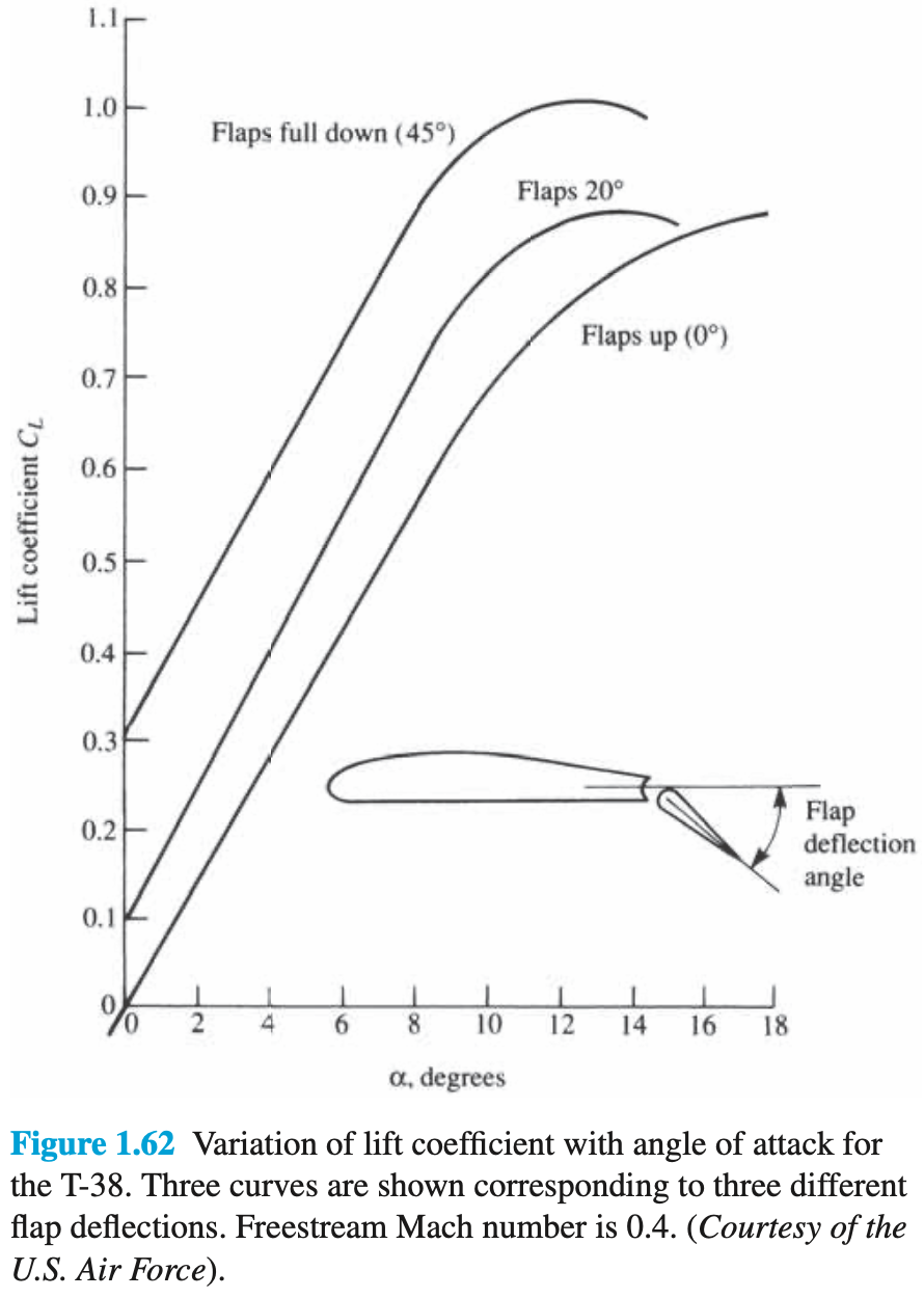
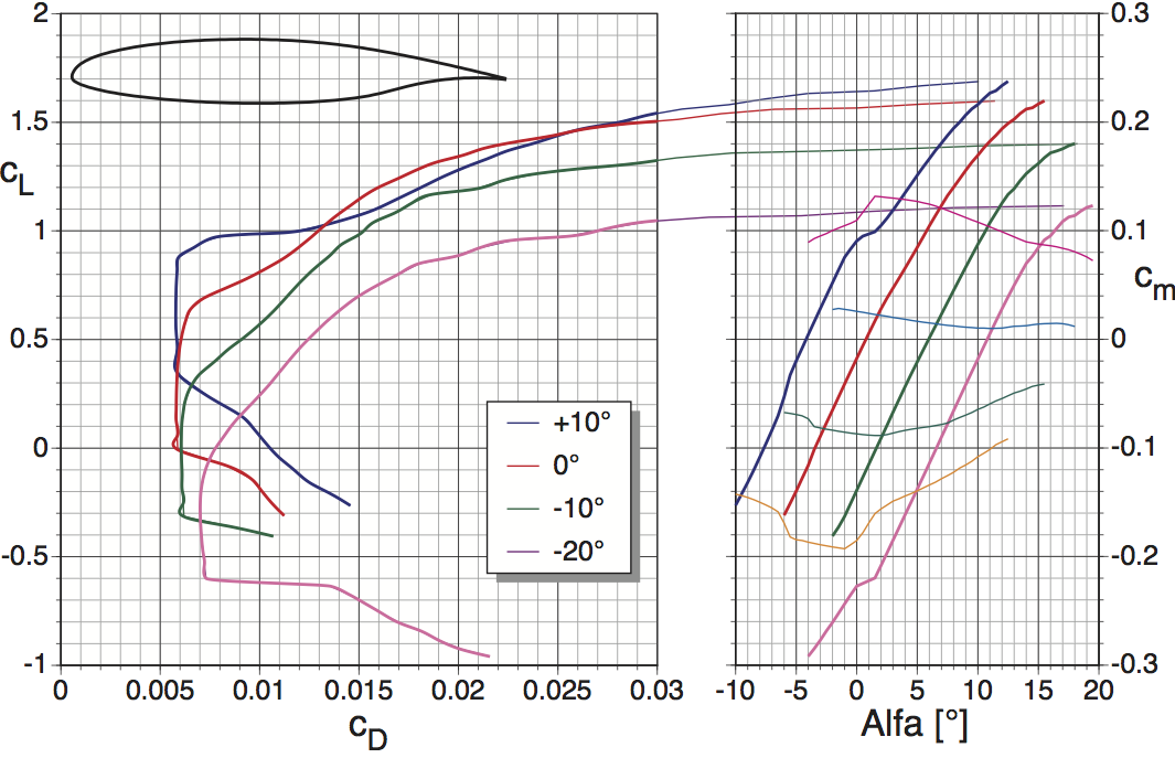
In the following picture, can see how the drag bucket changes for the given airfoil with different flap settings. For example, if takeoff
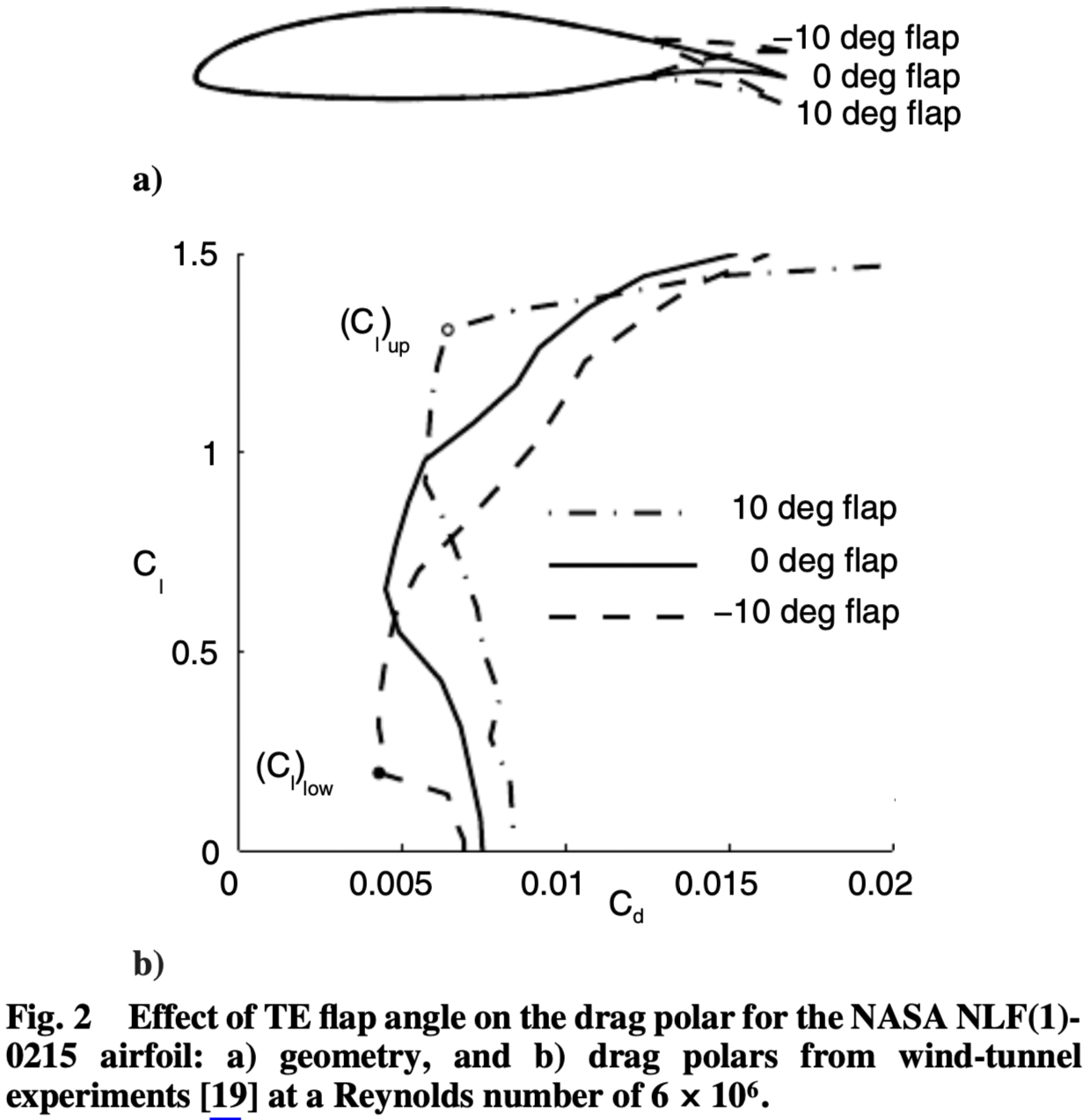
In the following picture, can see how the drag bucket changes for the given airfoil with different flap settings.
Flap Definitions
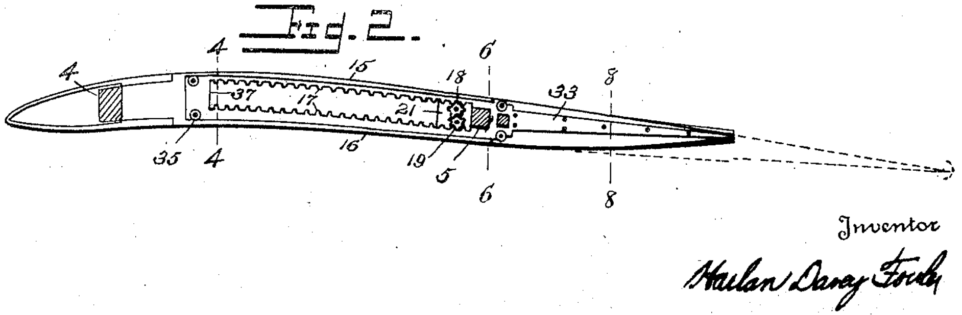
- The original 1921 patent by Harlan Davey Fowler was for a flap which would "maintain the general curvature and upper camber of the airfoil"
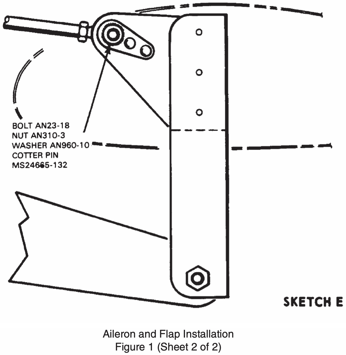
- Both the definitions by Roskam, "Plain trailing edge flaps are formed by hinging the rear-most part of a wing section about a point within the contour" and Sadraey, "hinged at the wing trailing edge" imply that the point about which a plain flap pivots must be within the cross section of the airfoil.
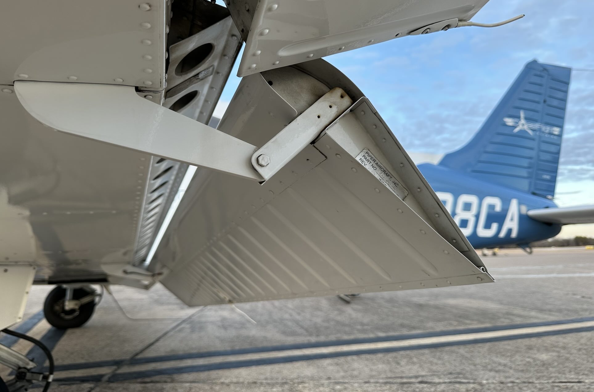
- Flaps such as those found on the Piper Archer or Cirrus SR22 whose pivot point is well outside of and below the airfoil cross section are therefore slotted flaps.
For more on flap definitions see
NASA The Wind and Beyond Volume II: Reinventing the Airplane
Key feature of the Fowler flap is a rearward translation of the flap resulting in an increase in the effective wing chord and correspondingly an increase in wing area
Mohammad H. Sadraey - Aircraft design : a systems engineering approach:
A Fowler flap has a special mechanism such that when deployed, it not only deflects downward but also translates or tracks to the trailing edge of the wing. The second feature increases the exposed wing area...
Jan Roskam - Airplane Aerodynamics and Performance:
The Fowler flap (see Figure 3.22d) employs the same principle as the slotted flap, but it also moves backward while deflecting downward. The backward motion increases the effective wing area.
Slots
- A leading-edge slot is a fixed (non-closing) gap behind the wing's leading edge.
Slats
- Like a slot, but can be retracted when not needed
- Located on the leading edge
- Delays airflow separation allowing higher angles of attack by redirecting airflow from under the wing to the top delaying separation
Spoilers
Trim Controls
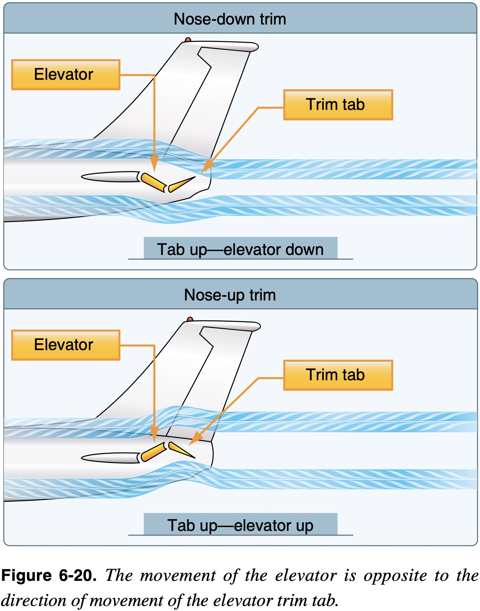
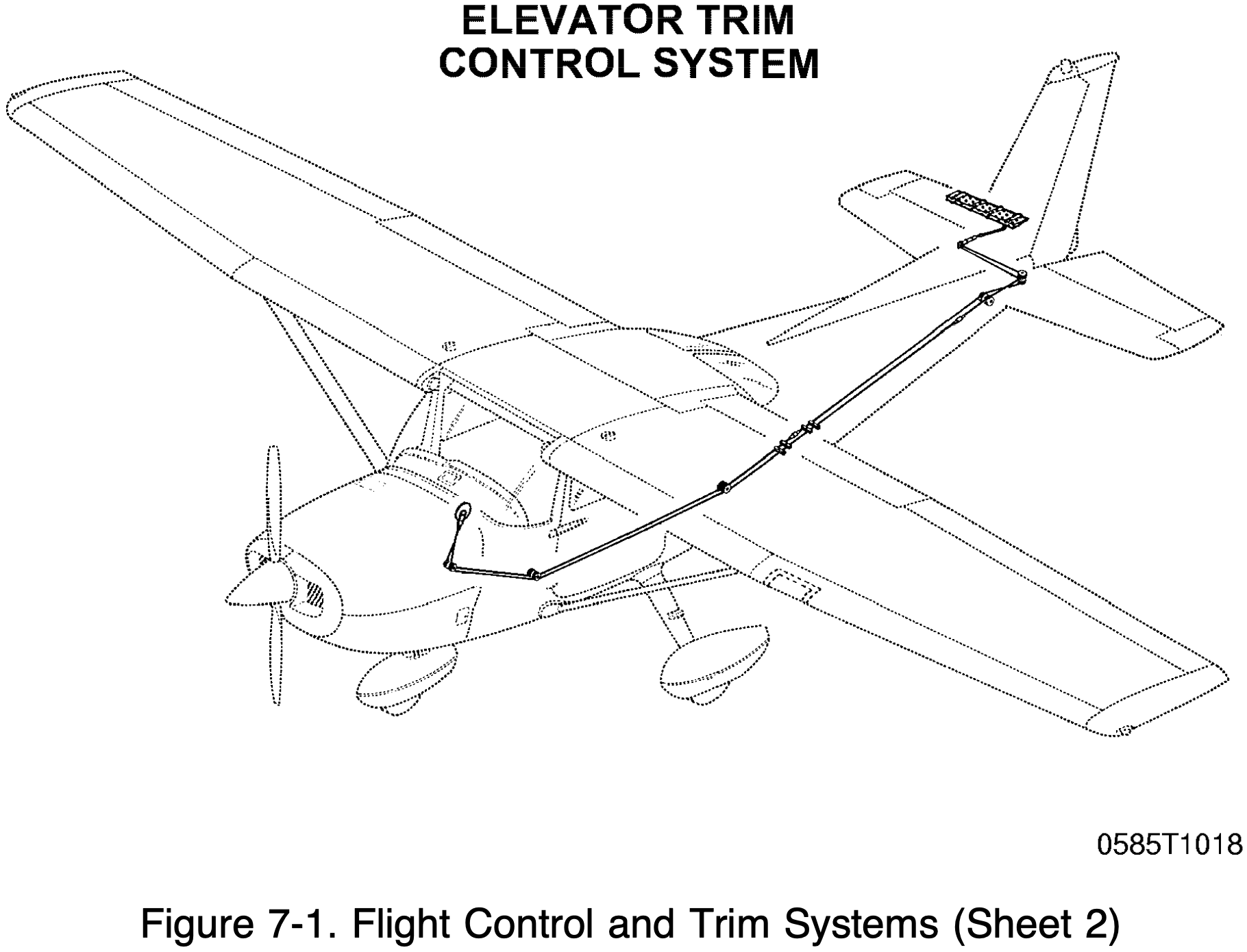
Trim Systems
Used to relieve the pilot of the need to maintain constant pressure on the flight controls.
- Trim systems usually consist of flight deck controls and small hinged devices attached to the trailing edge of one or more of the primary flight control surfaces.
- Some trim and related systems
- Trim tabs
- Balance tabs
- Like automatic trim tabs
- Antiservo tab
- Move in same direction as stabilator (opposite movement of balance tab)
- Designed to affect control feel
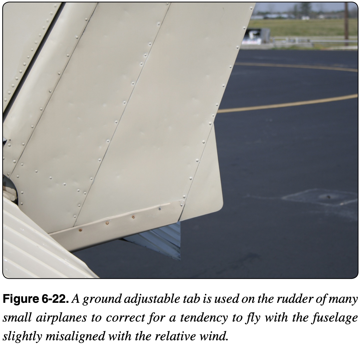
- Ground adjustable tab

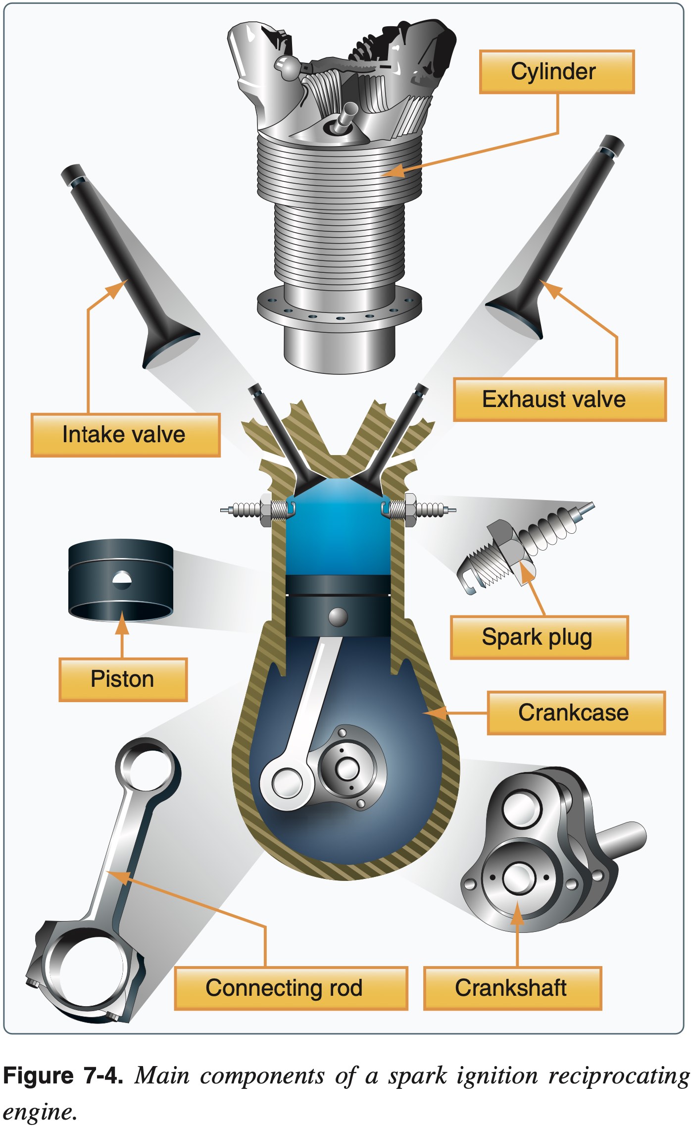
Powerplant
- Reciprocating engines
- Theory of operation
- Cylinder count, displacement, and horsepower
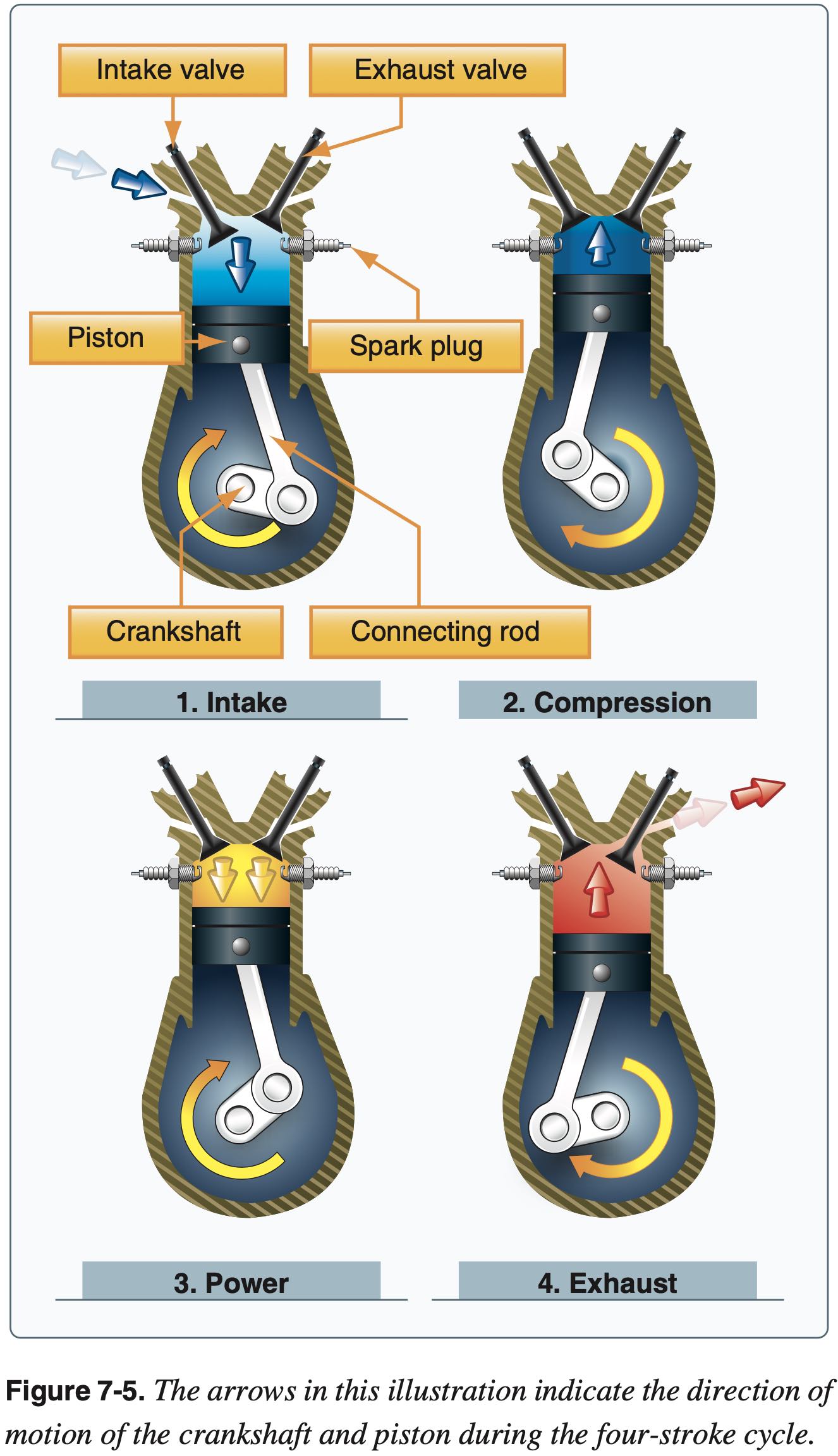
- How a 4-stroke cylinder works
- Basics of 2-stroke
- SAFETY: Why we need to learn this?
- Types
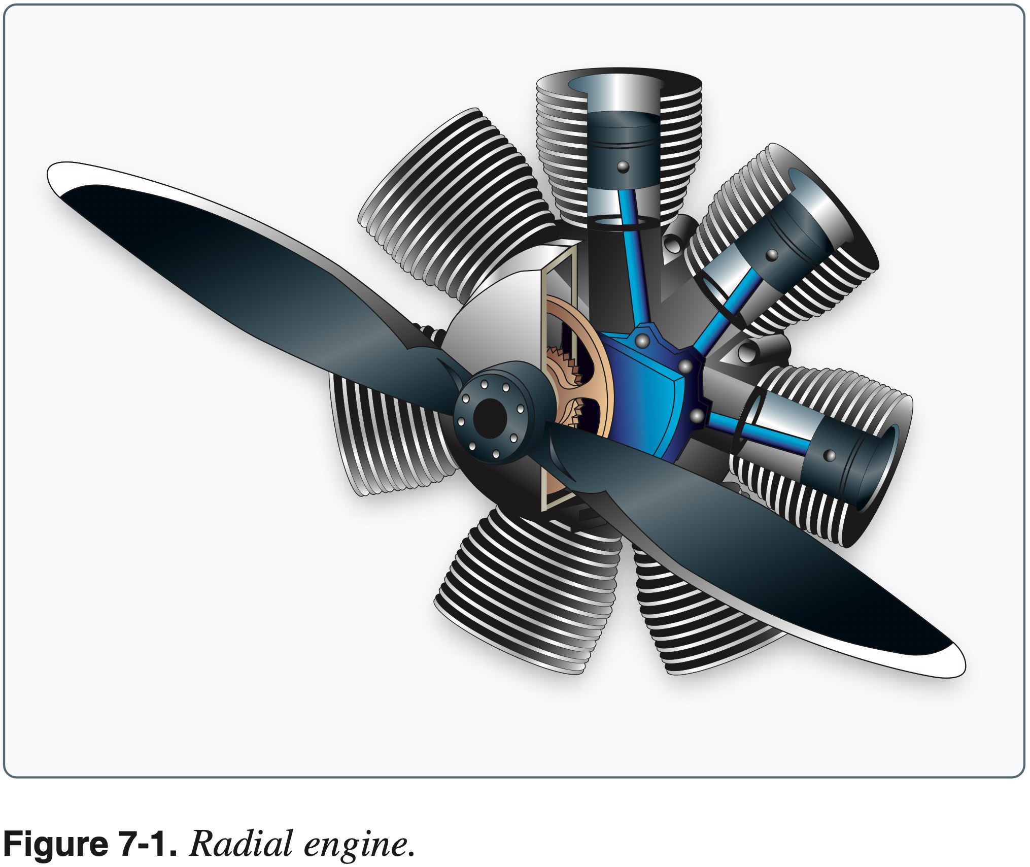
- Radial
- Generally good power-to-weight but large frontal area
- Inline
- Small frontal area, poor cooling at rear cylinders
- V-type
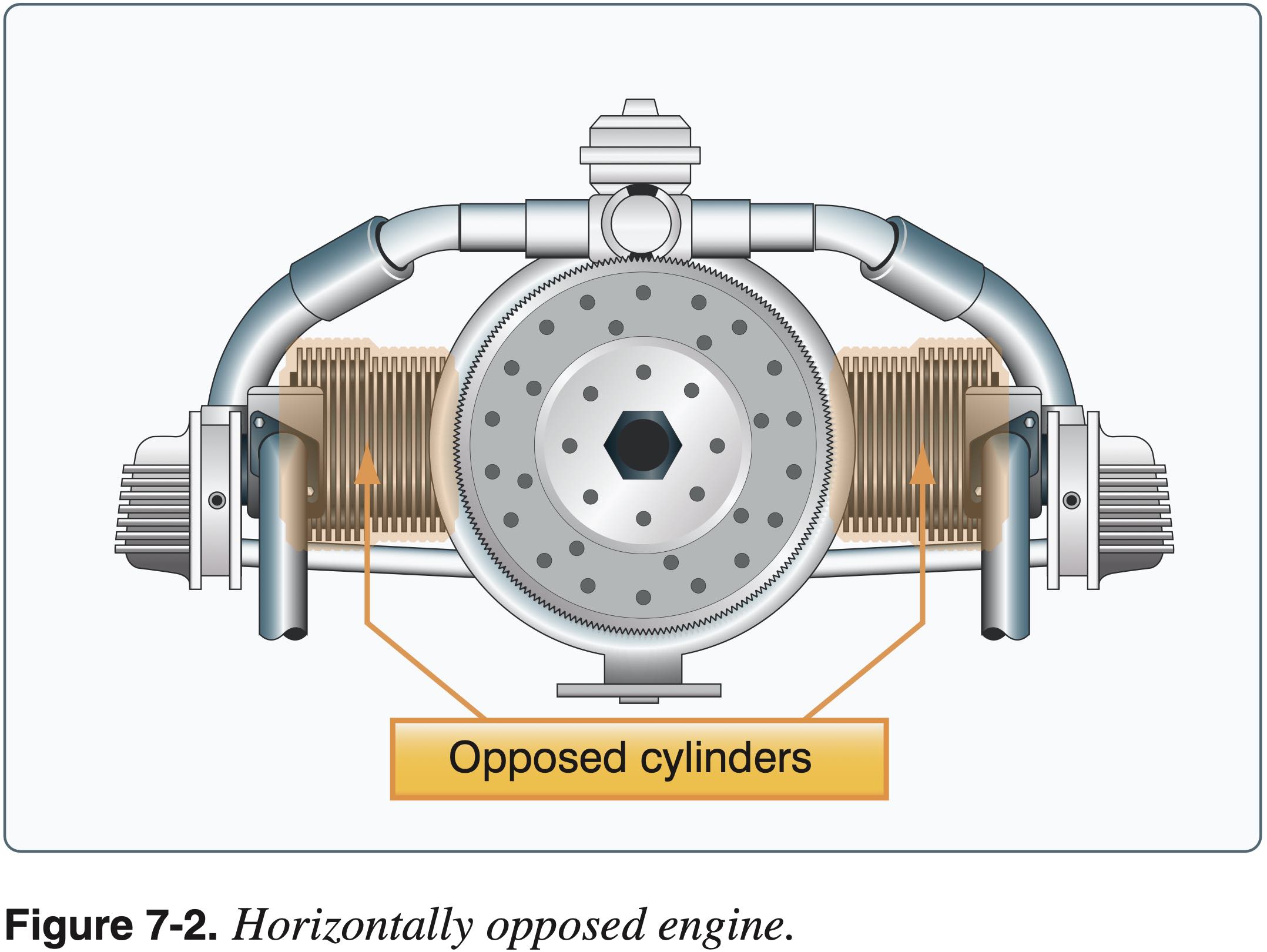
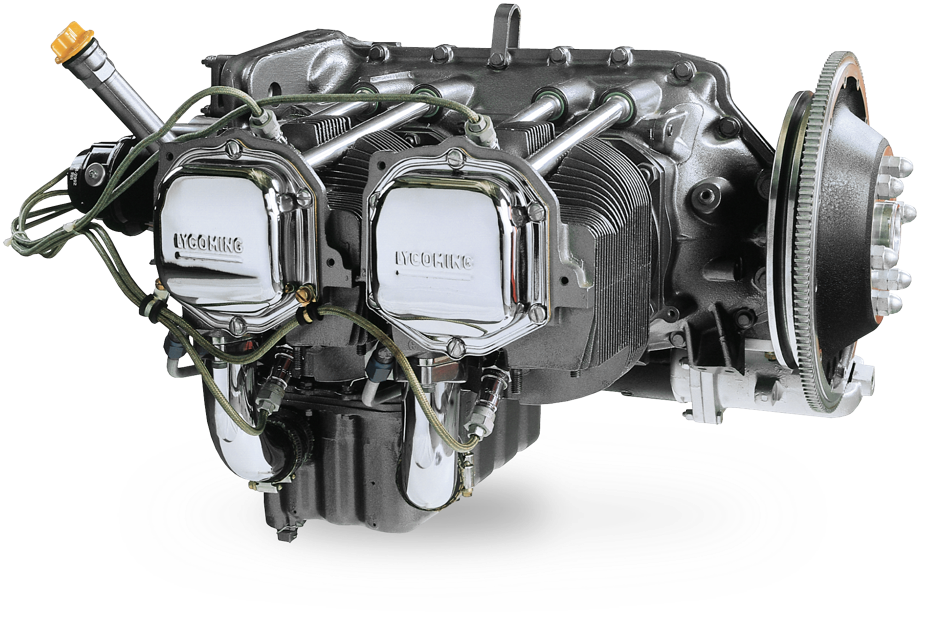
- Horizontally opposed
- Good power-to-weight, and reasonably small frontal area
- Radial
- General consideration of reciprocating engines
- Power-to-weight ratio
- Cooling (for example in horizontally opposed engine rear cylinders get less air)
- Frontal area (drag)
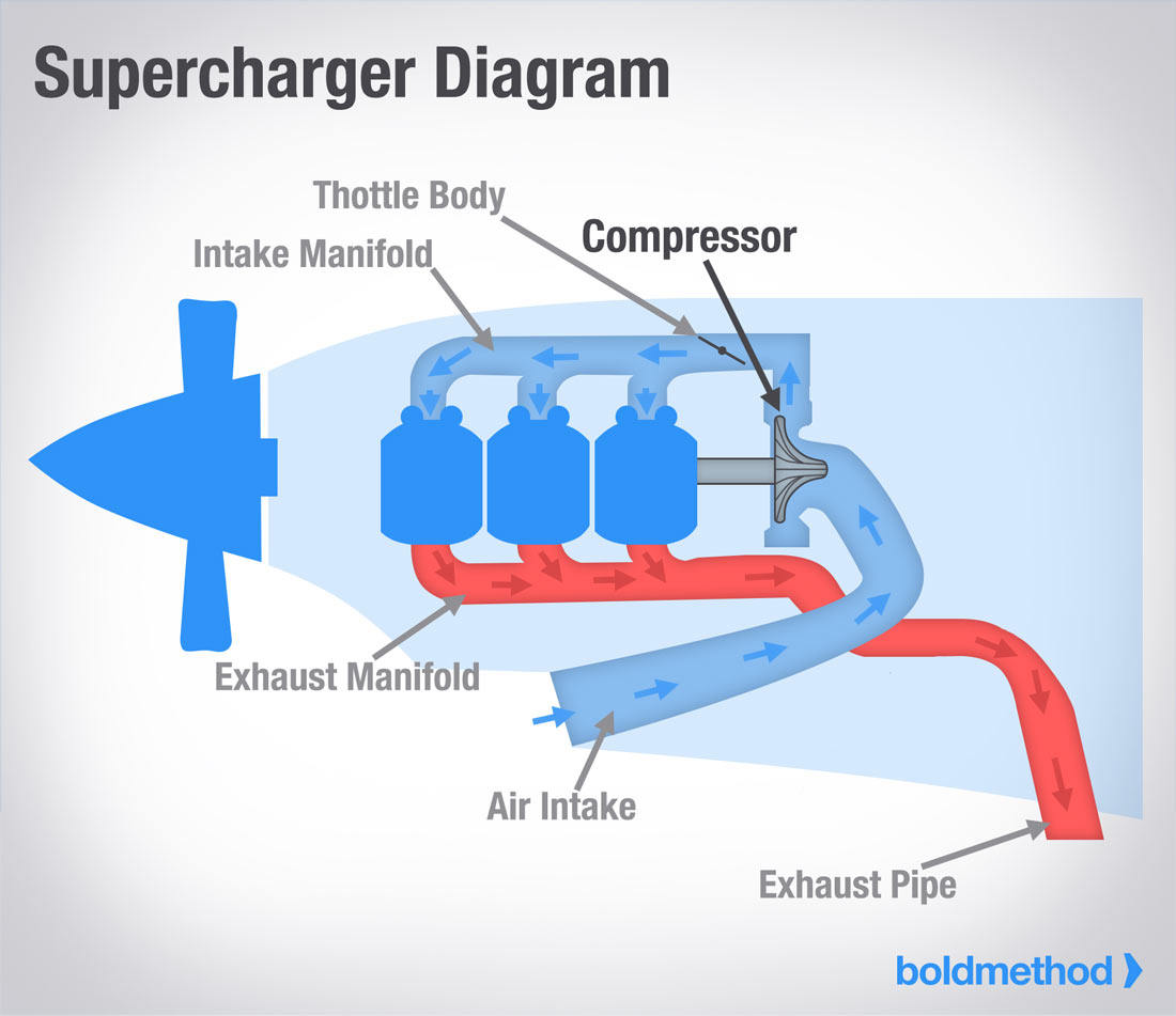
- Supercharging and Turbocharging
- Wastegate
- Critical Altitude
- SAFETY: Overboost condition
- Theory of operation
- Fuel-air ratios are by weight
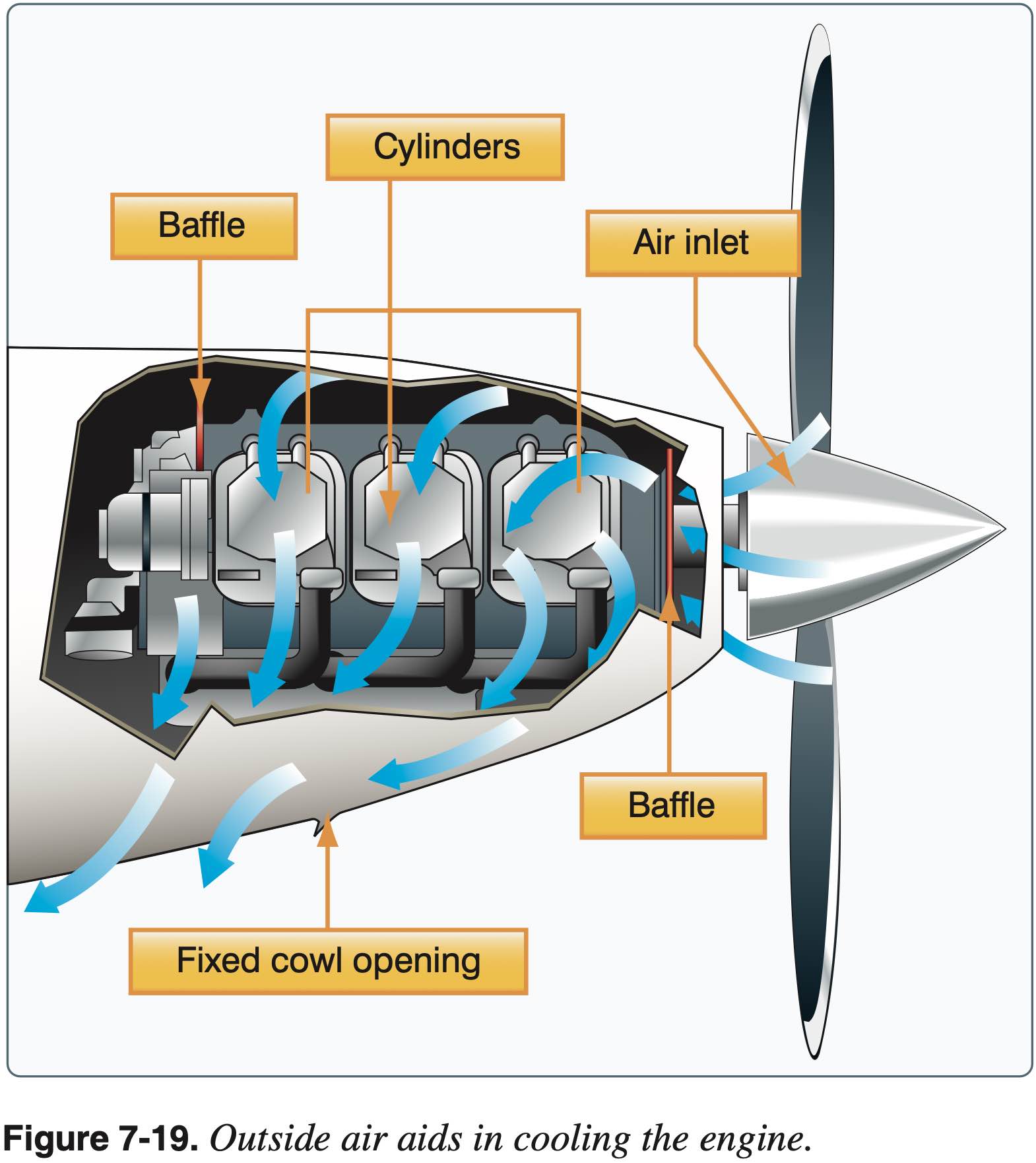
Cooling system
- Air cooled via inlet
- Considerations during ground operations and flight
- Cylinders have fins to increase surface area and dissipate heat
- Position into wind during runup
- High power and low speed configurations
- Cruise climb for cooling
- Shock cooling
- Cowl Flaps
- Use oil temperature gauge and cylinder head temperature (CHT) gauge
- If temp is high increase airspeed, enrich the mixture, and/or reduce power
- Operating the engine at higher than its designed temperature can cause the following, as well as permanent engine damage
- Loss of power
- Excessive oil consumption
- Detonation
- Operating the engine at low temps is also bad
Exhaust system
- Discharges combustion byproducts into free stream
- Shroud around muffler captures waste heat for heating cabin and using for defrost
- EGT and leaning procedures
- SAFETY: Heating & CO poisoning (symptoms, remedies)
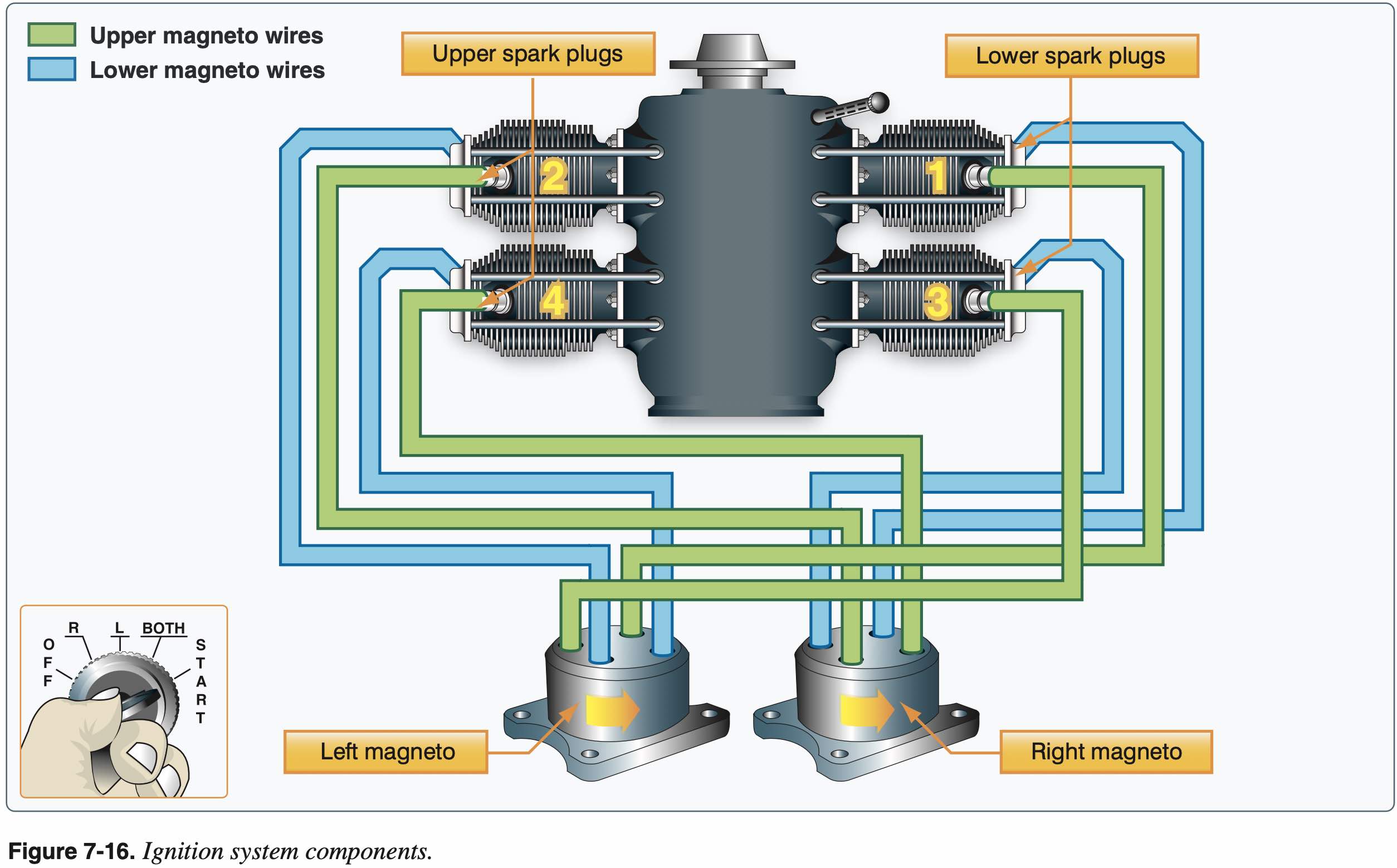
Ignition System
- Two magnetos and spark plugs for redundancy
- Also provides more power via more complete combustion
- Doesn't require battery power to work
- No drop of RPM during single magneto runup check indicates broken magneto wires
- Magneto check R magneto first so that after checking L it's one click back to BOTH
- Spark plug fouling results from running too rich mixture
- Detonation
- Instantaneous combustion
- Occurs at high power settings when too lean
- Often occurs when using lower grade of fuel
- Preignition
- When hot spots in cylinder ignites air/fuel mixture prematurely
- Detonation and preignition often occur simultaneously and one may cause the other.
- Since either condition causes high engine temperature accompanied by a decrease in engine performance, it is often difficult to distinguish between the two.
- To avoid detonation
- Ensure that the proper grade of fuel is used.
- Keep the cowl flaps open while on the ground
- Enriched the mixture, as well as a shallow climb angle, to increase cylinder cooling during takeoff and initial climb
- Avoid extended, high power, steep climbs.
- Monitor the engine instruments in flight to verify proper operation
- SAFETY: P-lead & ground check after landing
- P-lead is the primary lead of the magneto
- Grounding the P-lead disables the magneto
- If magnetos aren't grounded, they stay on or "hot" even when the key is out
Impulse Coupling
- In most general aviation aircraft, ignition timing is fixed to provide maximum power at redline
- This is somewhere around 20 degrees before top dead center (BTDC)
- In order to change the ignition timing to enable starting an impulse coupling is used
- The impulse coupling mounts between the engine and magnetos and contains some springloaded flyweights and an internal spring
- At low RPM it engages, delays rotation of the magnetos and winds up the spring, releasing somewhere past TDC to initiate the spark
SAFETY
When turning the prop by hand, always rotate it opposite the direction it normally spins to prevent engaging the impulse coupling and potentially trigger ignition of the magneto p-lead is damaged.
Induction System
- Two types
- Carbureted
- Fuel injected
- Alternate engine air intake system
- Airflow & Alternate Air
- Can be manual or automatic
- In fuel injected planes, alternate air can be automatic via spring-loaded bypass
- Manifold pressure
- As altitude increases, performance reduction
- SAFETY: Blockage indications
- For carburetors and carb heat see fuel system section below
- Impact icing
- Can affect fuel-injected aircraft by icing over the air filter
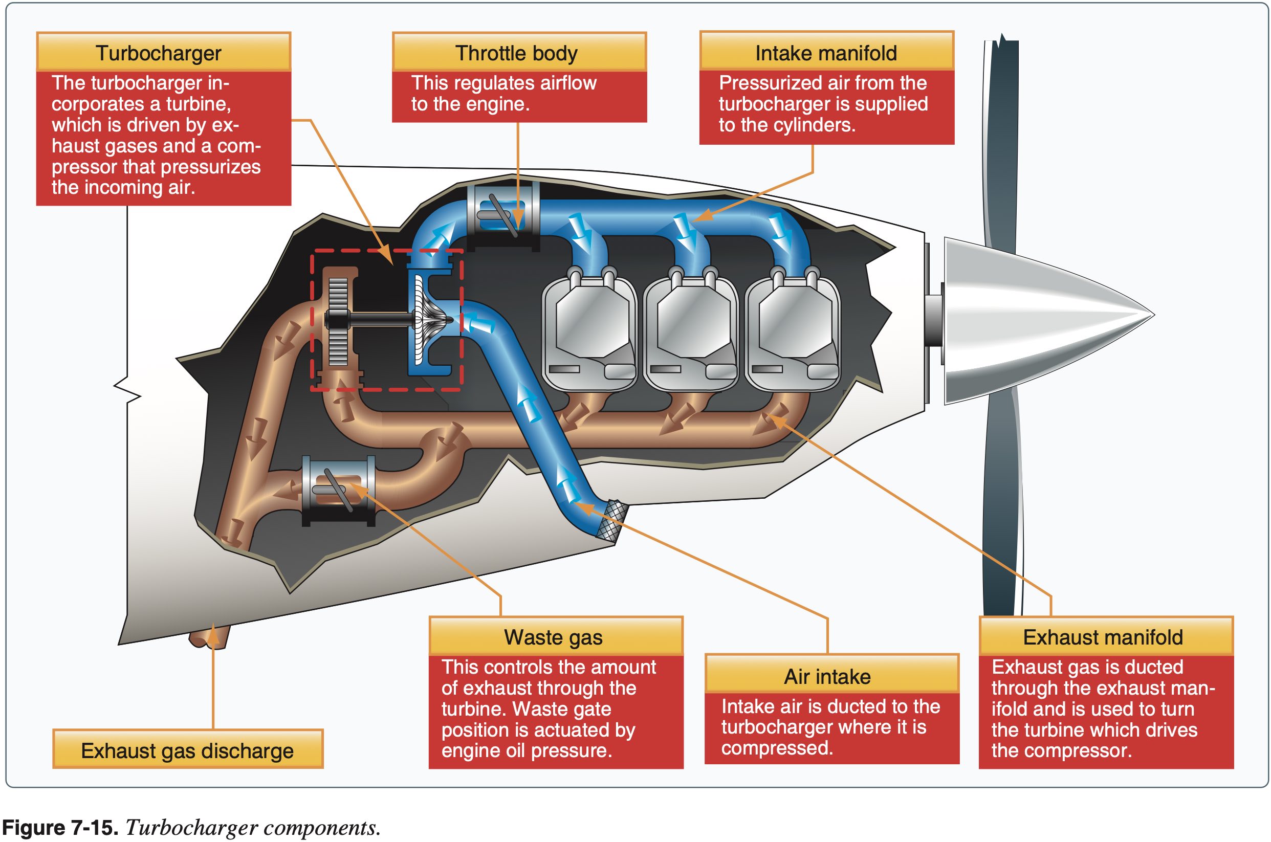
- Turbo
- Compressor is driven by a turbine that itself is driven by exhaust gasses
- Turbonormalizer is used to increased the intake air pressure to sea level or slightly above
- Turbocharger can pressurize the intake air substantially above sea level pressure
Propeller
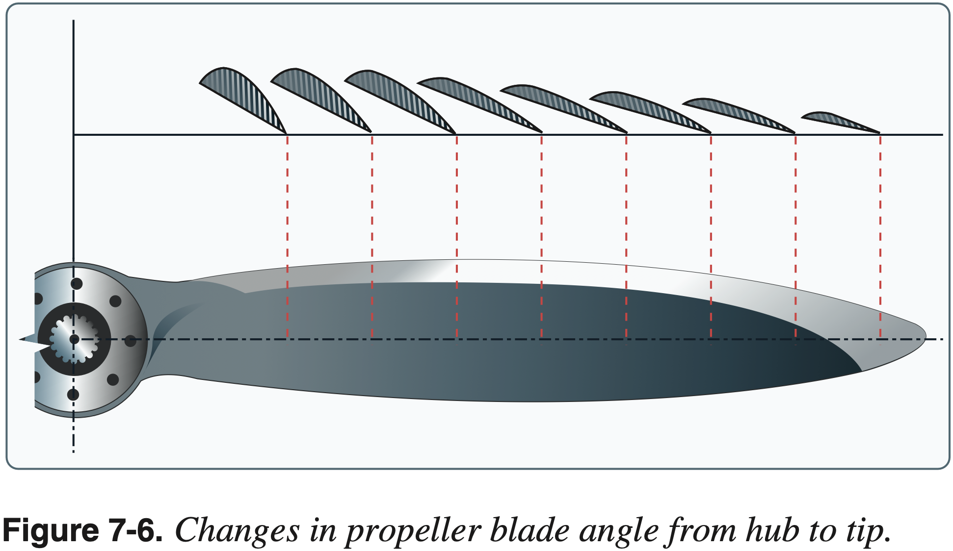
- Is a rotating airfoil
- Subject to all characteristics of airfoil as wing (induced drag, stalling)
- Constant-speed propeller vs fixed pitch
- Governor
- Efficiency
- Geometric pitch
- Distance a propeller theoretically would advance in one rotation based only on the incidence angle of the propeller blades
- Effective pitch
- Distance a propeller actually advances in one revolution
- Propeller slip
- Difference between geometric pitch and effective pitch
- Fixed pitch
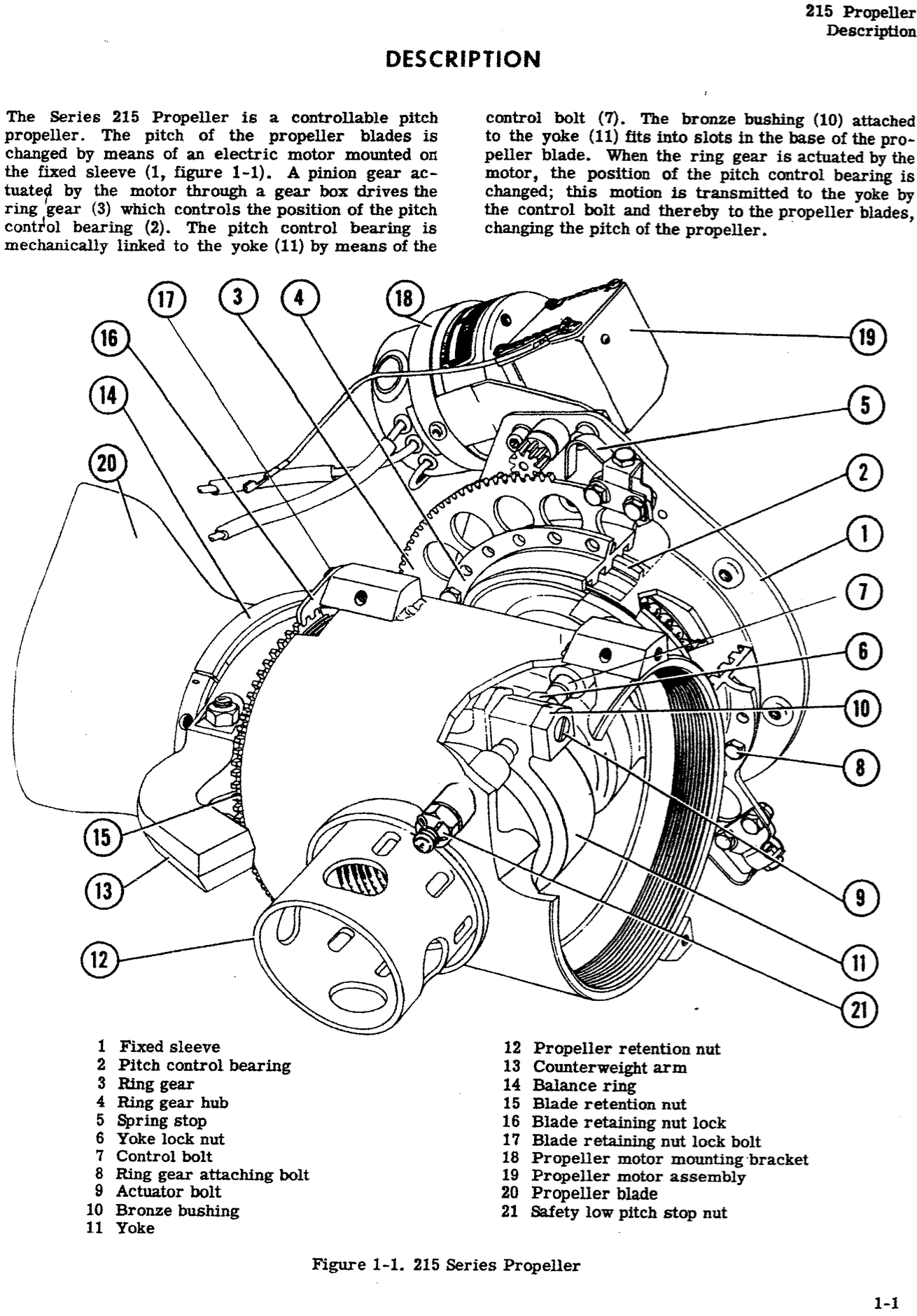
- Variable pitch
- Pitch of the propeller can be changed
- For example, the Beechcraft 215 had an electrical adjustment mechanism
- Ground adjustable
- Adjusted to desired position on the ground using tools
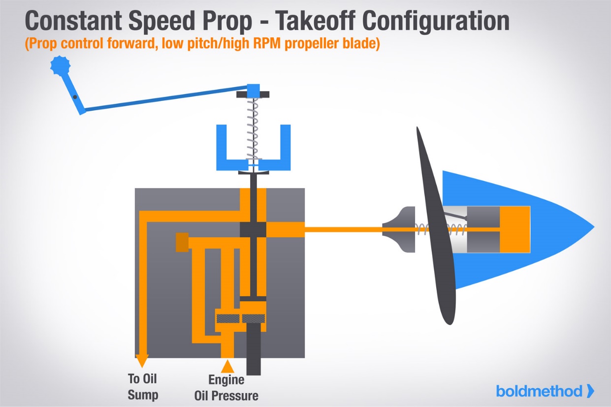
- Constant speed
- A type of variable pitch controlled by a governor so the pitch is automatically adjusted to maintain a specific RPM
- Pitch of the propeller can be changed
Multi-engine Airplane Propeller
- In most single-engine planes the "default" prop position is full-forward
- In most multi-engine planes the "default" prop position is feathered
- This provides better single engine performance in the event of an engine failure
- Oil pressure is required to unfeather the prop
- This "default" feathered position is provided by counterweights as well as springs or nitrogen, which aids to force oil out of the prop hub and allow the prop to feather
- Springs or nitrogen are there to help when RPMs are lower and the counterweights are less effective
- Aerodynamic forces tend to drive the propeller to the low pitch, high RPM position
- Below approximately 800 RPM, a reduction in centrifugal force allows small anti-feathering lock pins in the pitch changing mechanism of the propeller hub to move into place and block feathering so the prop doesn't feather on every engine shutdown.
- Therefore, if a propeller is to be feathered, it needs to be done before engine speed decays below approximately 800 RPM.
- Propeller synchronizer - device which can be engage after the props are set to approximately the same RPM to automatically synchronize them
- Propeller syncrophaser - like a synchronizer, but compares and adjusts the positions of each of the individual blades of the propellers in their arcs to significantly reduce propeller noise and vibration
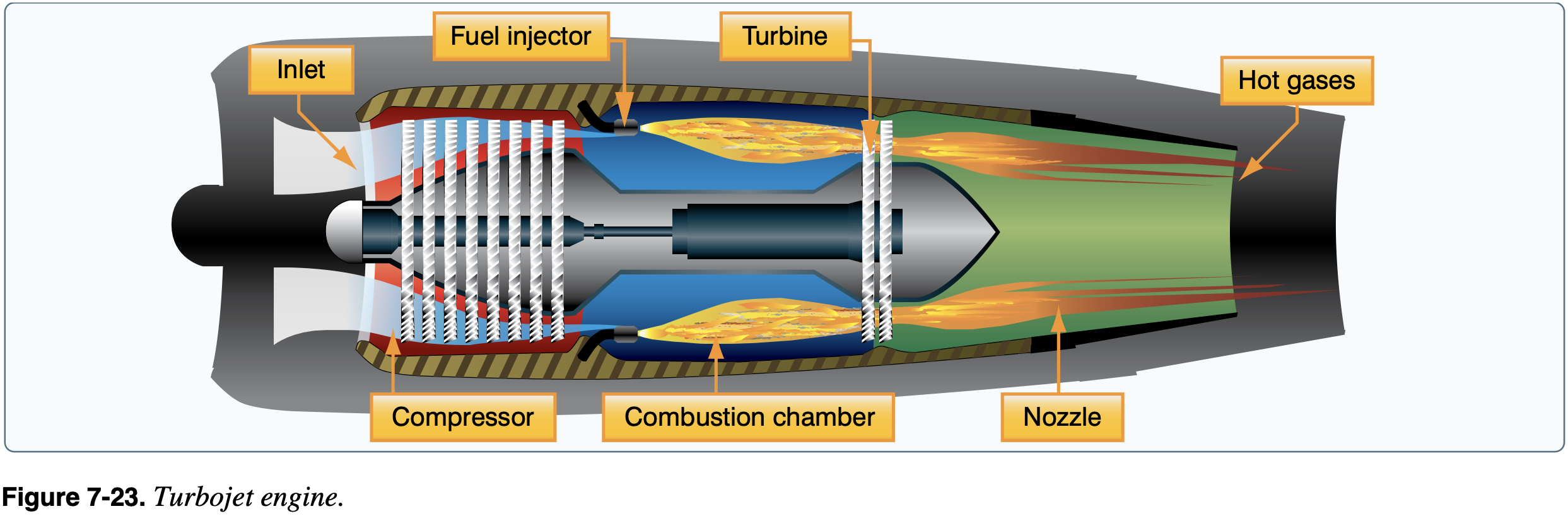
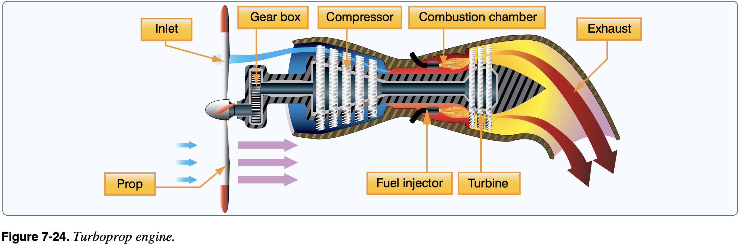
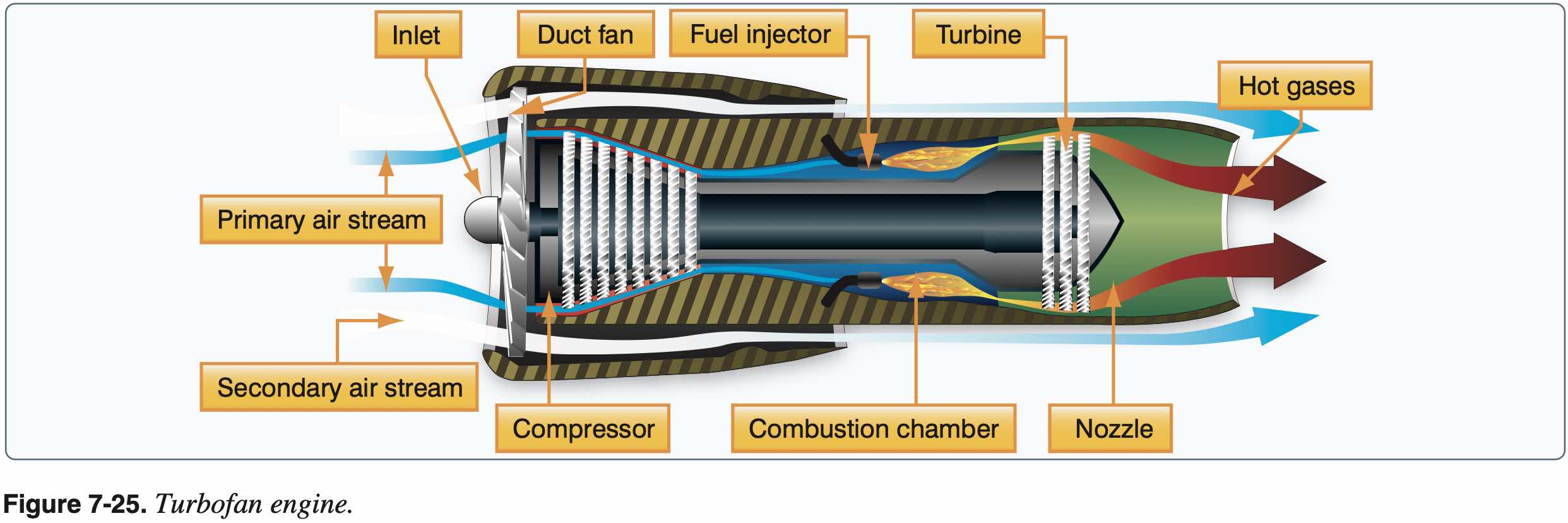
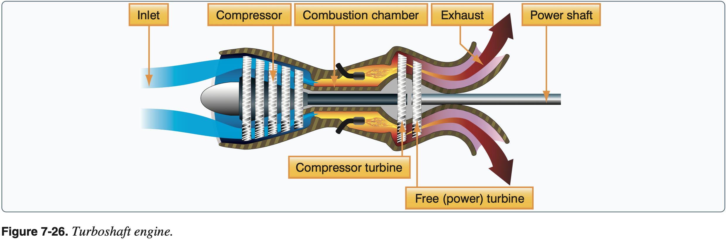
Turbine Engines
- Turbojet
- Turboprop
- Turbofan
- Turboshaft
Fuel System
- Fuel delivery systems for reciprocating engines
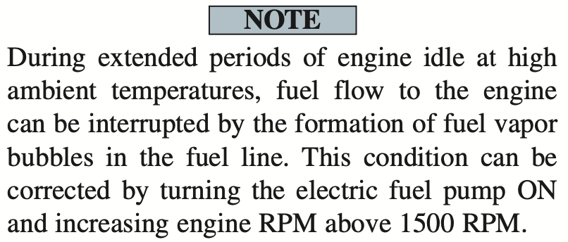
- Carburetor Systems
- Two types
- Float-type
- Pressure-type
- Float type is most common in small aircraft
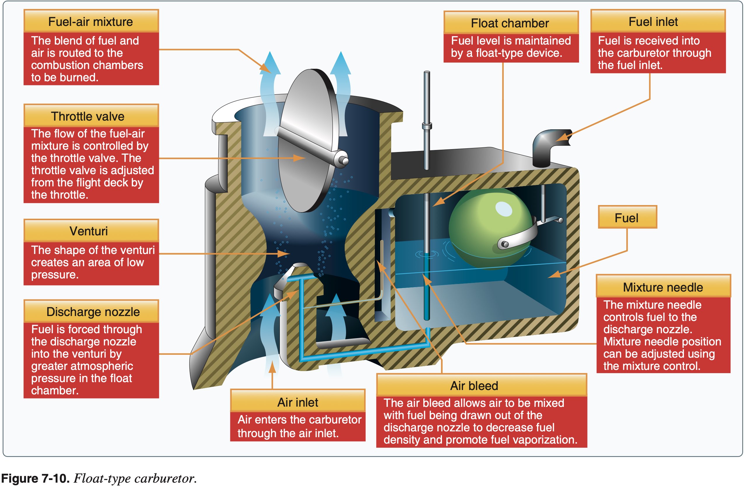
- Biggest disadvantage is icing
- Drop in temperature due to fuel vaporization takes place within the venturi
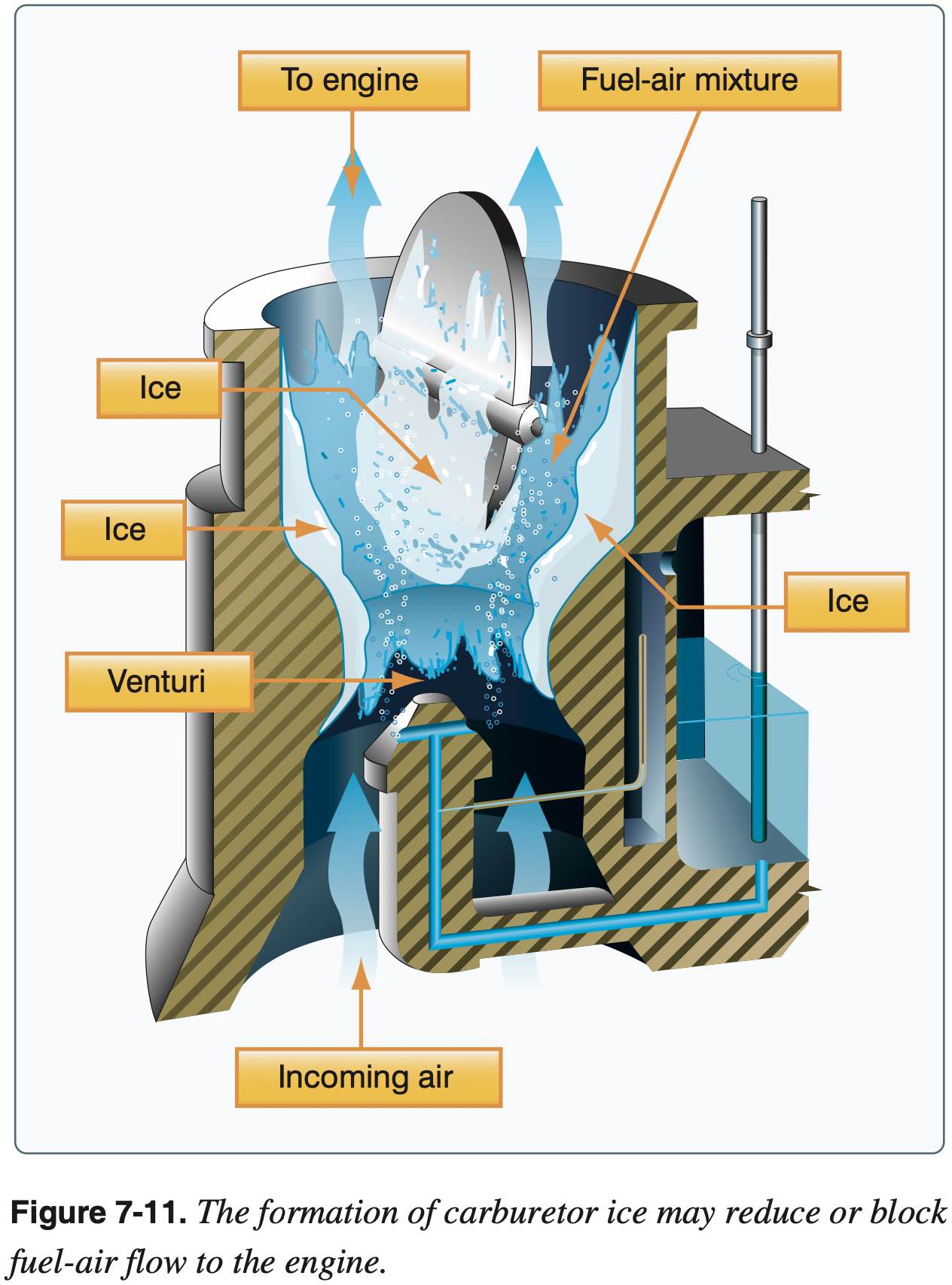
- Carburetor ice is most likely to occur when temperatures are below 70 °F or 21 °C and the relative humidity is above 80 percent.
- The first indication is decreased RPM / manifold pressure
- Most likely and dangerous when reducing power and descending
- Carb heat used for anti-icing (or alternate source of air if air filter clogs)
- Carb heat causes decrease in power up to 15 percent
- If detected, full carburetor heat should be applied immediately, and it should be left in the ON position until the pilot is certain that all the ice has been removed.
- If ice is present, applying partial heat or leaving heat on for an insufficient time might aggravate the situation
- Whenever the throttle is closed during flight, the engine cools rapidly and vaporization of the fuel is less complete than if the engine is warm. Also, in this condition, the engine is more susceptible to carburetor icing.
- Carb heat bypasses air filter
- Can be used in case of air filter blockage
- Carb heat off on short final to soft fields
- Two types
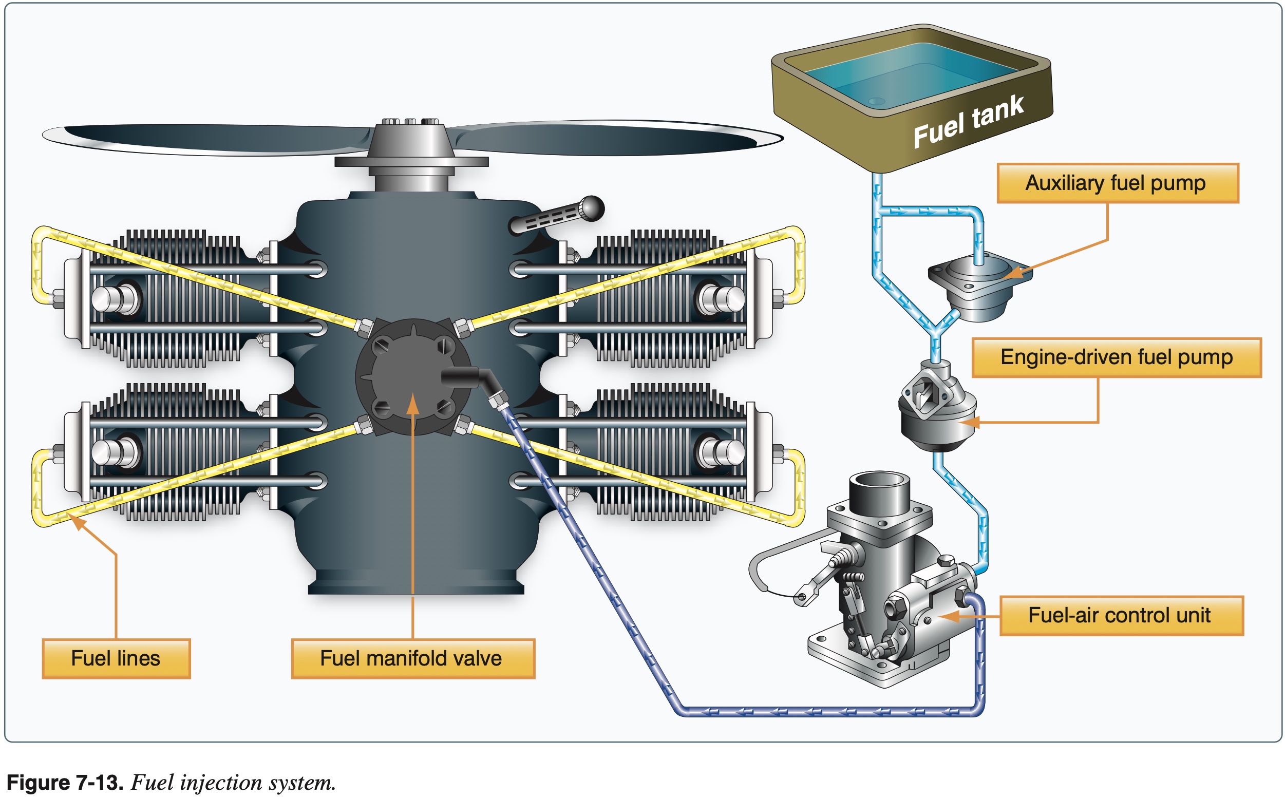
- Fuel injection
- The following are advantages of using fuel injection:
- Reduction in evaporative icing
- Better fuel flow
- Faster throttle response
- Precise control of mixture
- Better fuel distribution in cylinders
- Easier cold weather starts
- The following are disadvantages of using fuel injection:
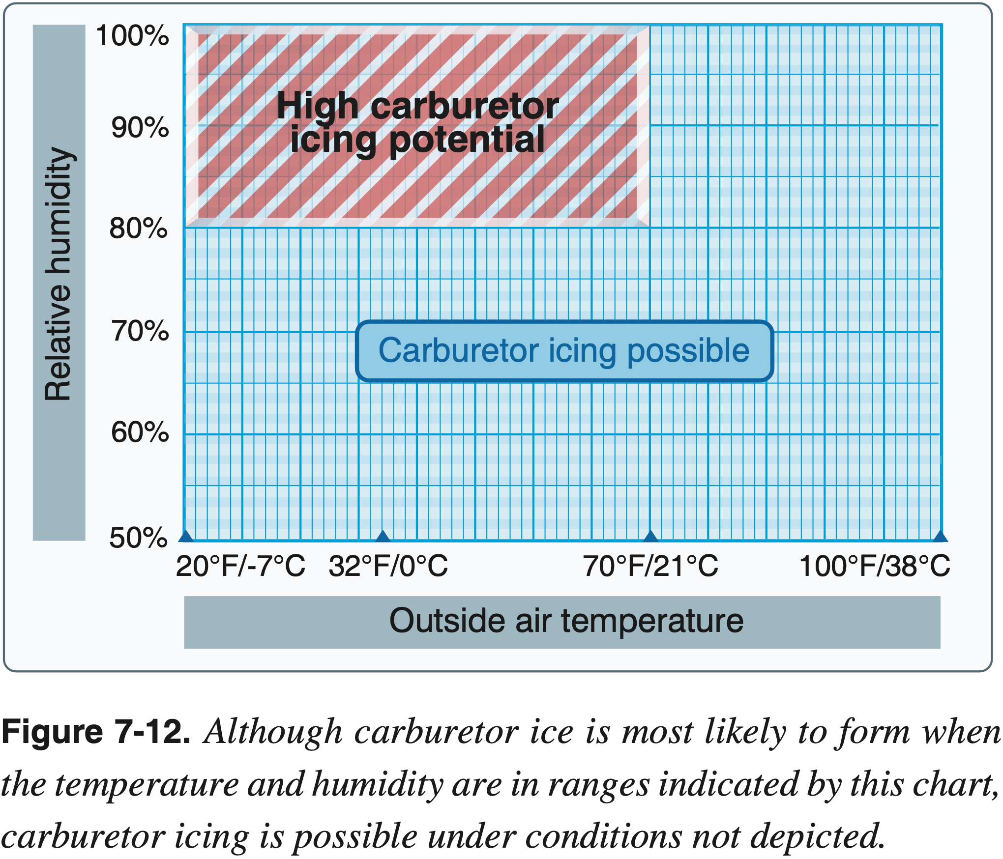
- Difficulty in starting a hot engine
- Vapor locks during ground operations on hot days
- If vapor locked on hot day when starting, point aircraft into wind and open oil access door
- Problems associated with restarting an engine that quits because of fuel starvation
- The following are advantages of using fuel injection:
- Carburetor Systems
- Mixture control
- Total mass of air in a given volume decreases with altitude
- Mixture used to decrease mass of fuel entering the cylinder as mass of air decreases
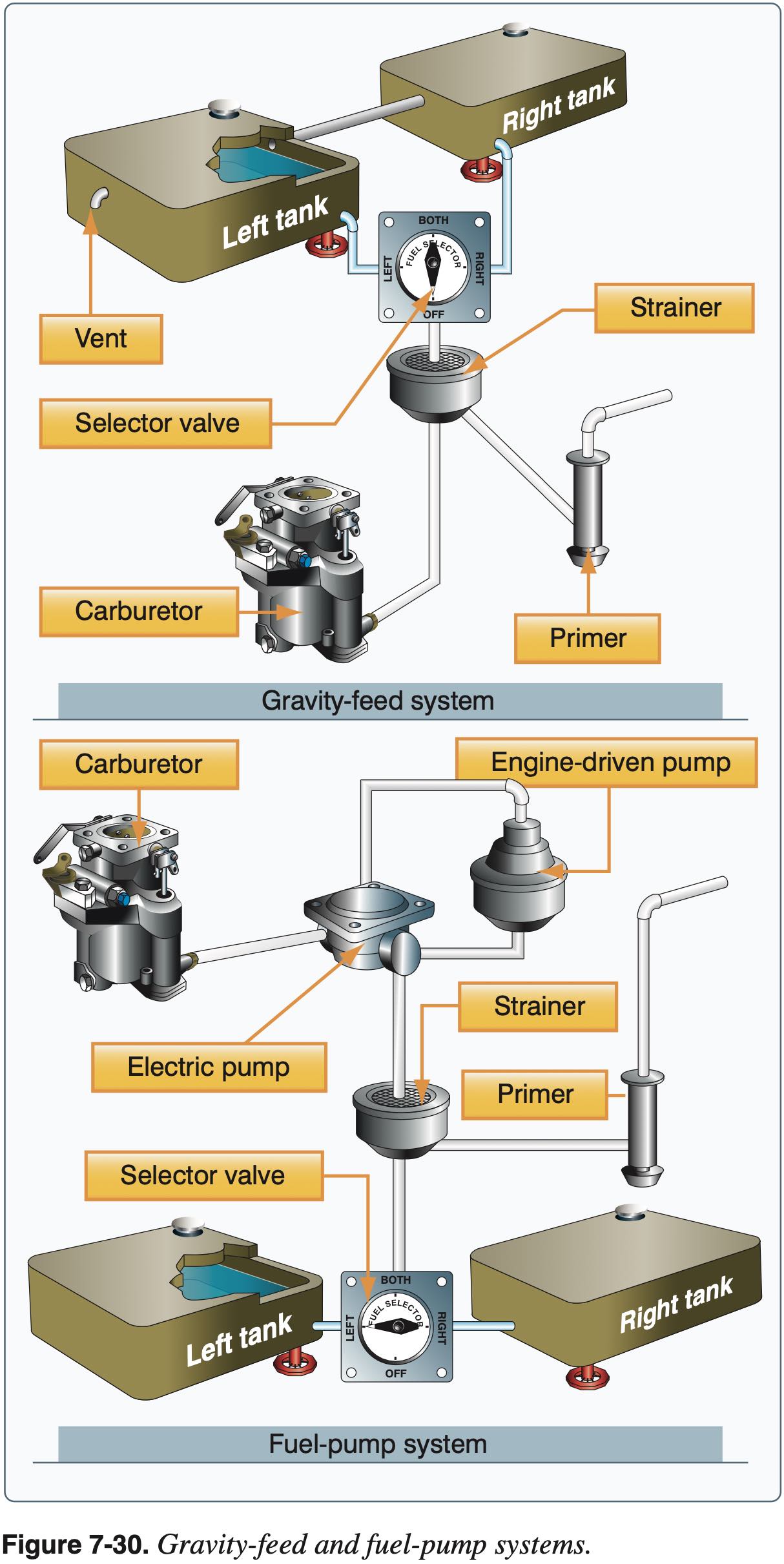
- Gravity-feed vs fuel-pump systems
- The gravity-feed system utilizes the force of gravity to transfer the fuel from the tanks to the engine.
- Aircraft with fuel-pump systems have two fuel pumps. The main pump system is engine driven with an electrically-driven auxiliary pump provided for use in engine starting and in the event the engine pump fails.
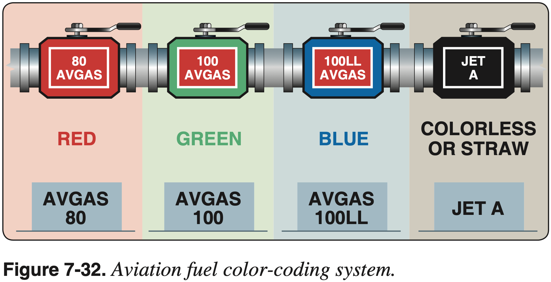
- Fuel grades
- 80 Red
- 100 Green
- 100LL Blue
- JET A Straw
- G100UL Orange (amber)
- Fuel tanks
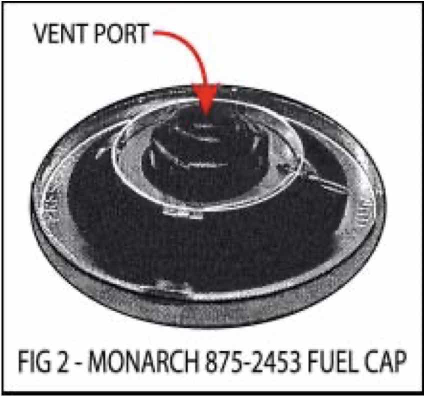
- Fuel tank venting
- Fuel tanks should be filled after each flight or after the last flight of the day to prevent moisture condensation within the tank
- Hotter it is, more water can be dissolved in fuel
- Importance of sumping fuel
- Fuel system icing
- Refueling
- Static electricity
- Grounding procedures
- Fuel gauges
- Only are required to read empty when tanks are empty
- Verify visually and/or with dip stick
- Flooded engine
- Increases risk of engine fire
- See emergency procedures for the aircraft what to do in event of engine fire during start
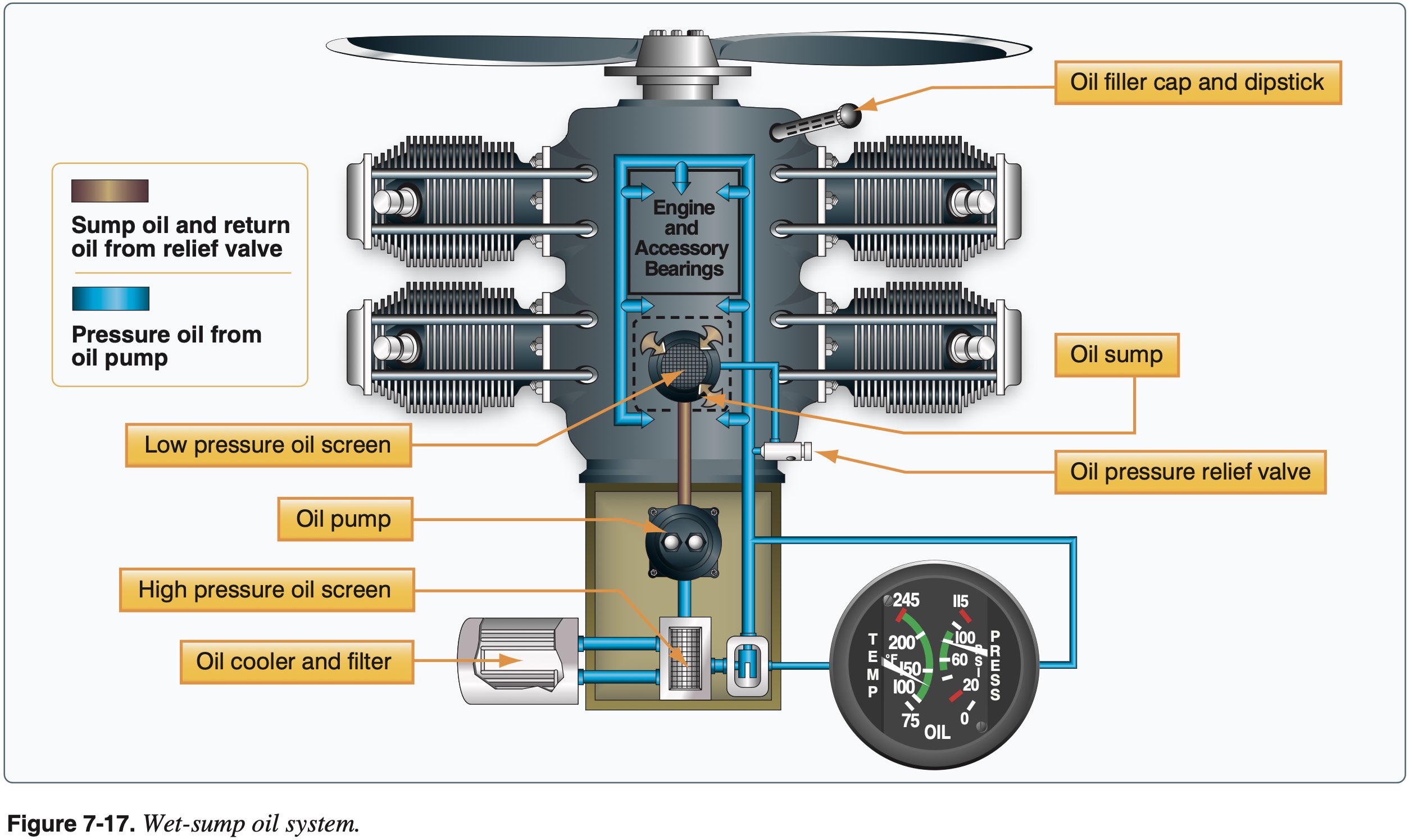
Oil System
- The engine oil system performs several important functions
- Lubrication of the engine's moving parts
- Cooling of the engine by reducing friction
- Removing heat from the cylinders
- Providing a seal between the cylinder walls and pistons
- Carrying away contaminants
- SAFETY: Dangers of losing oil pressure (blocked, pump, leak, defective gauge) – check periodically during flight
- Wet sump
- Oil is in pan at the bottom of crankcase
- Dry sump
- Oil is stored in a separate tank
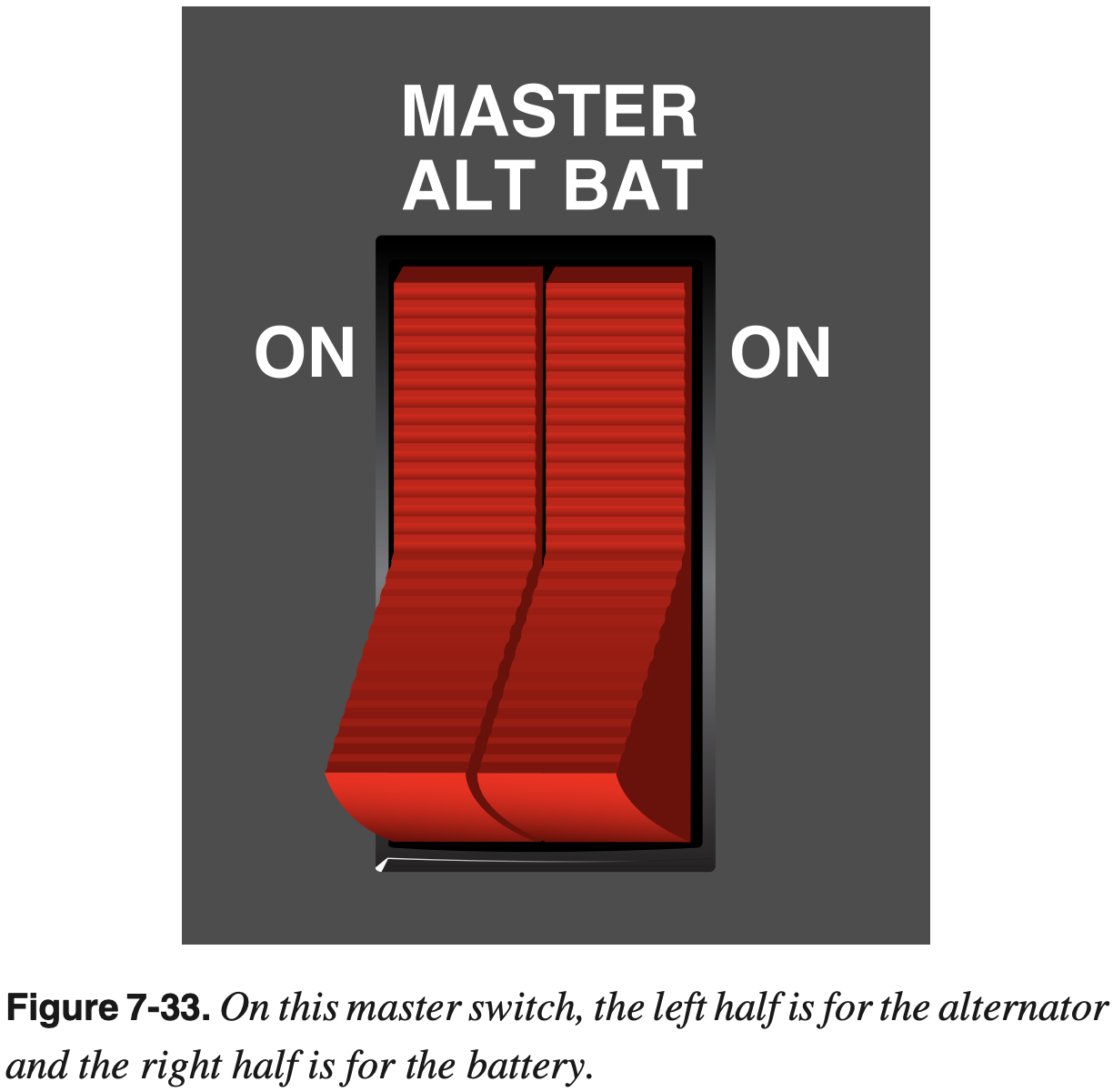
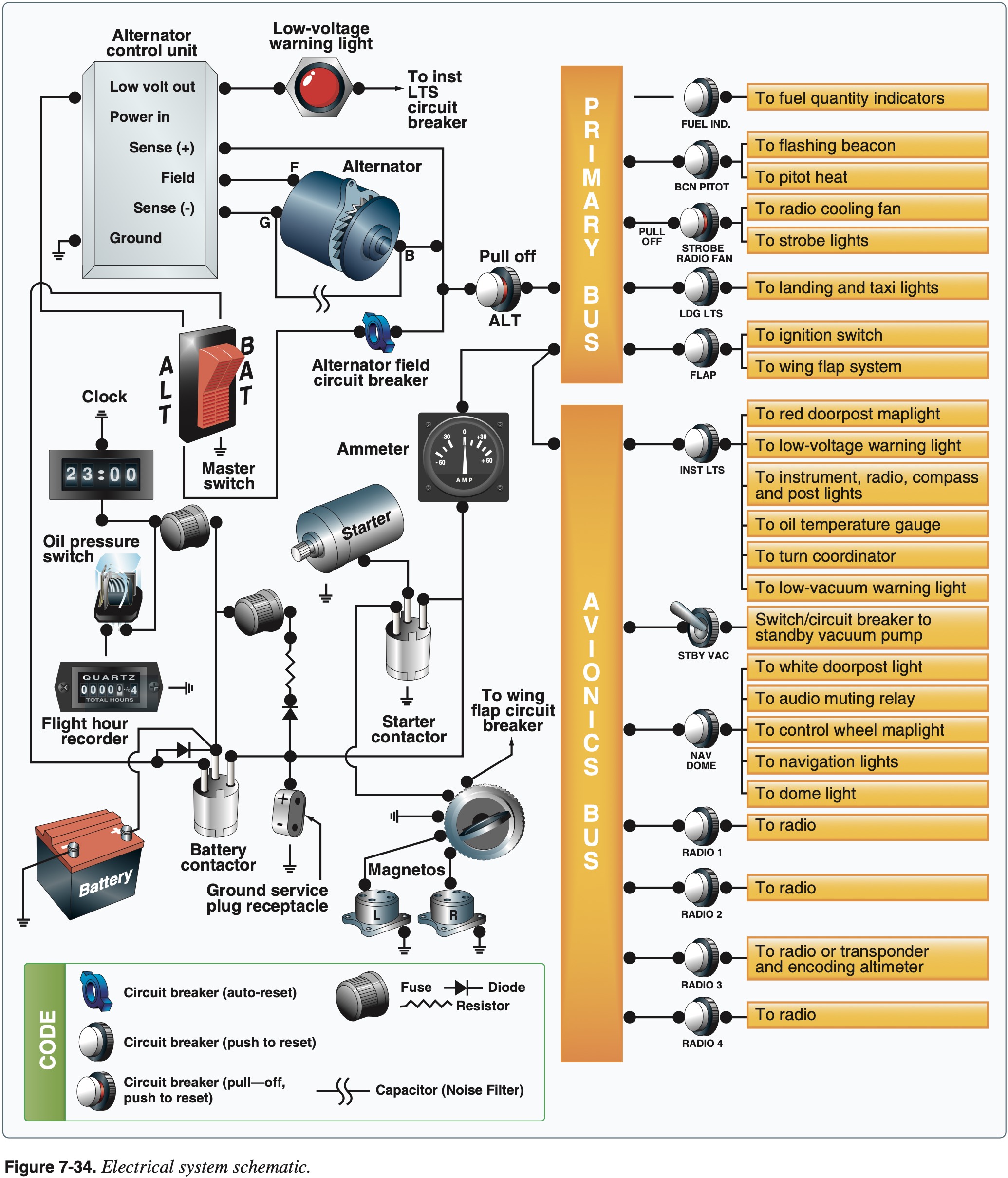
Electrical System
- Most planes 14 or 28 volt (DC) systems
- Alternator or generator supplies power
- Alternator provides more power than a generator at a lower RPM
- One of the basic differences between a generator and an alternator is the number of magnetic poles used to produce the electricity. Generators normally have 2 or 4 poles, while alternators have between 8 and 14 poles. The larger number of poles allows an alternator to produce its electrical power at a lower engine RPM than a generator.
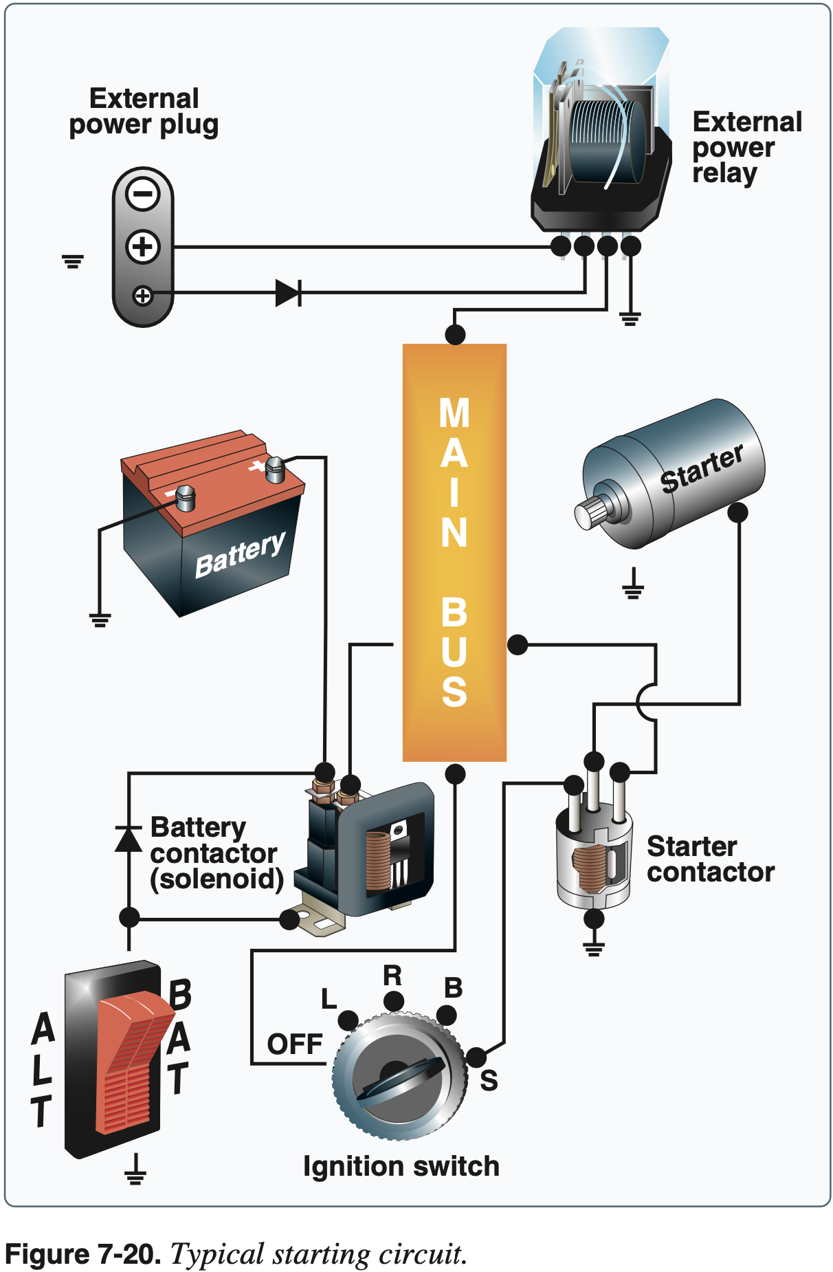
- Batteries store power
- Receptacle to connect plane to external power
- Good for cold weather starting
- Bus bar as common point for powered connections
- Fuses / breakers
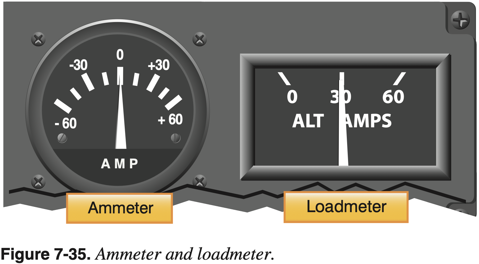
- Ammeter
- Positive is charging, negative is discharging
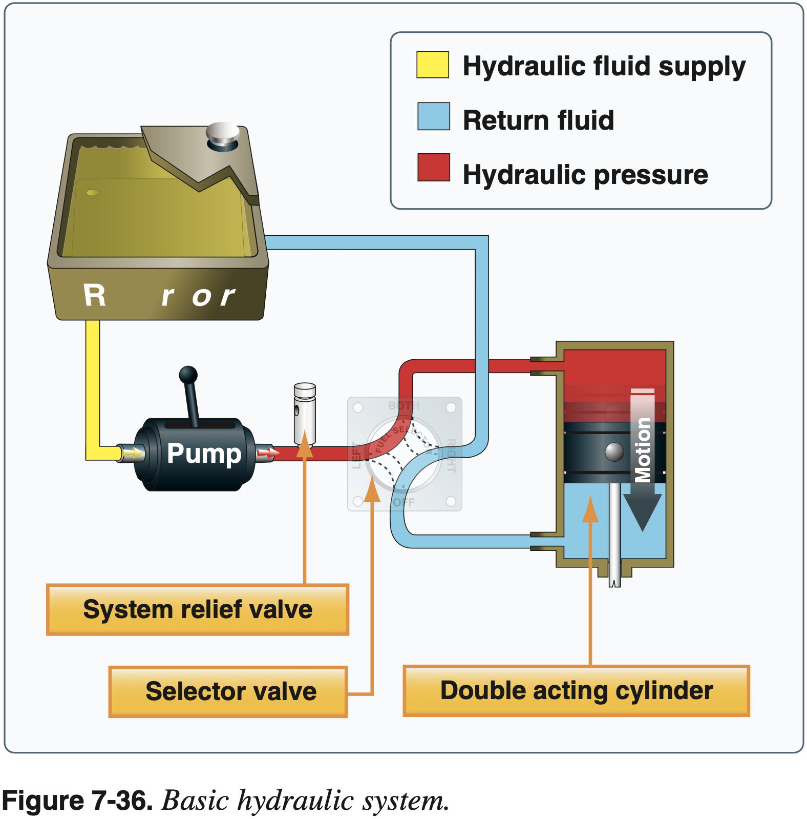
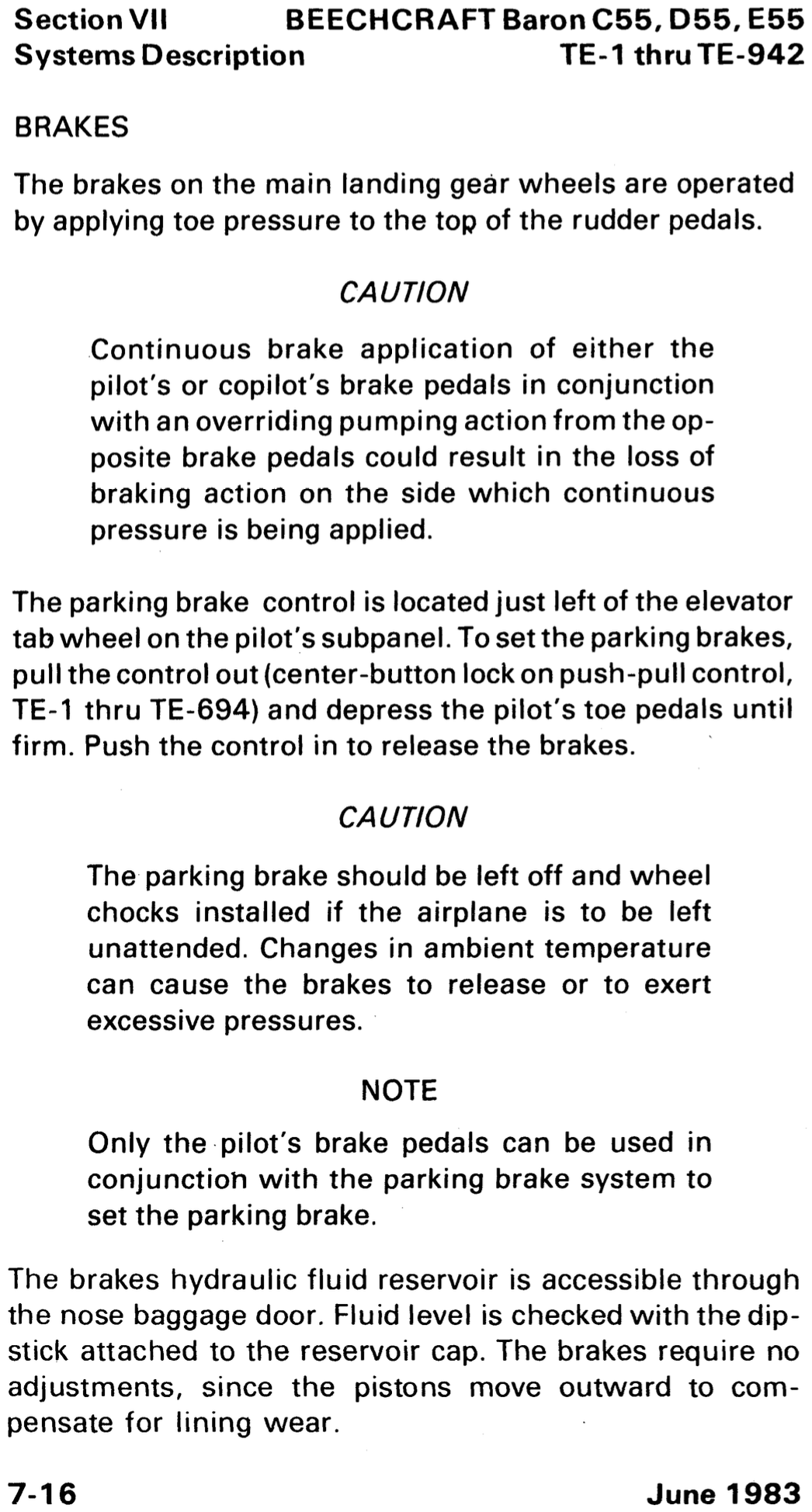
Hydraulic System
A basic hydraulic system consists of
- Reservoir
- Pump (either hand, electric, or engine-driven)
- Filter
- Selector valve
- Relief valve
- Actuator
Mostly found for landing gear
- Electric pump with hydraulic fluid
- Hydraulic pressure required to lower gear
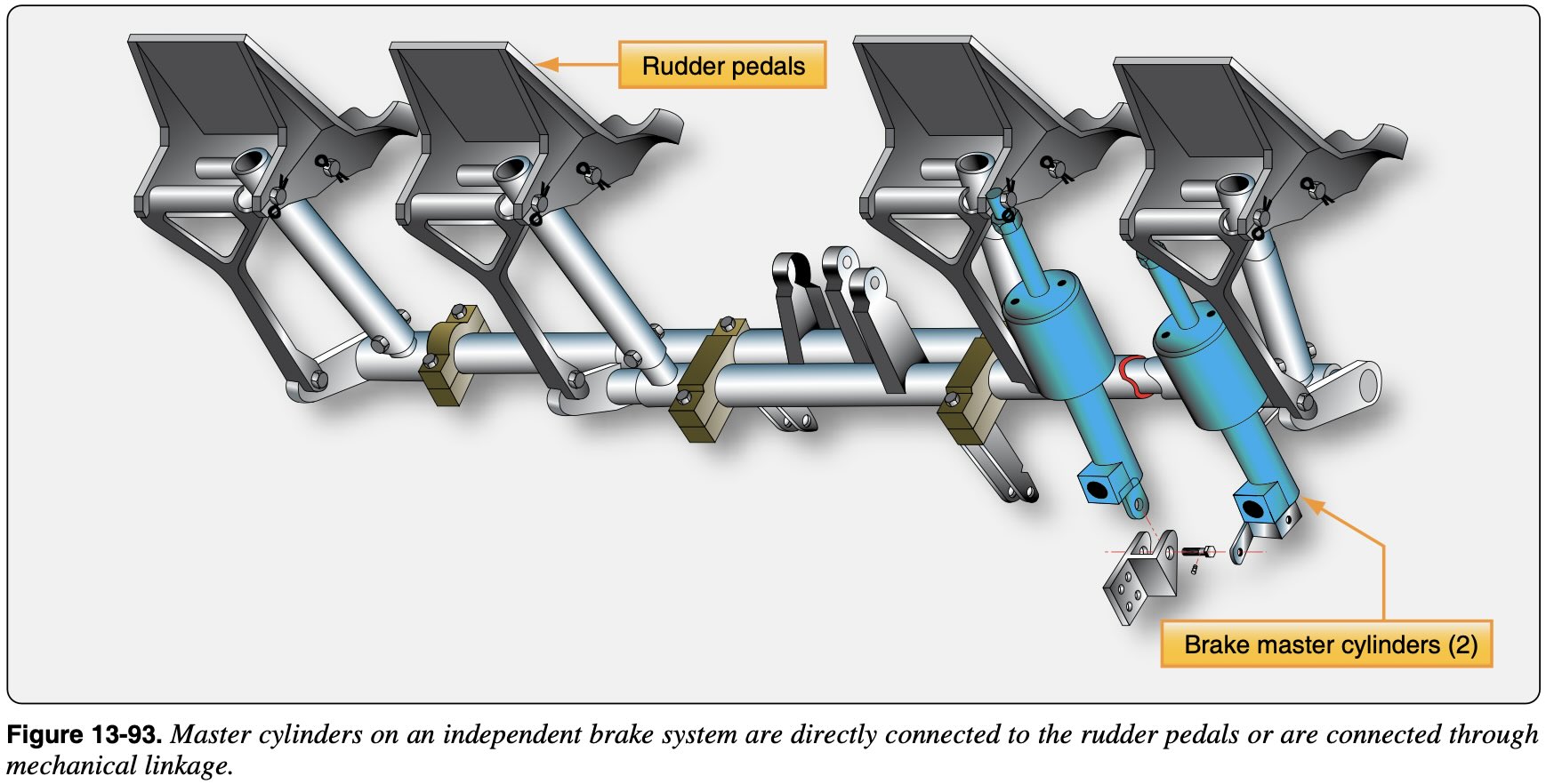
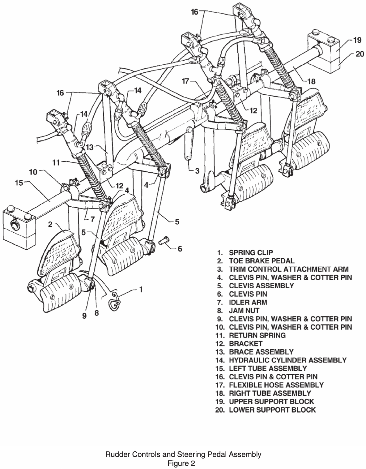
Brakes also a hydraulic system
Piper Archer has a separate master cylinder for the handbrake, see VB-2749 page 7-7:
The toe and hand brakes have their own master brake cylinders, but they share a common reservoir.

Landing Gear
- Wheels, floats, skis
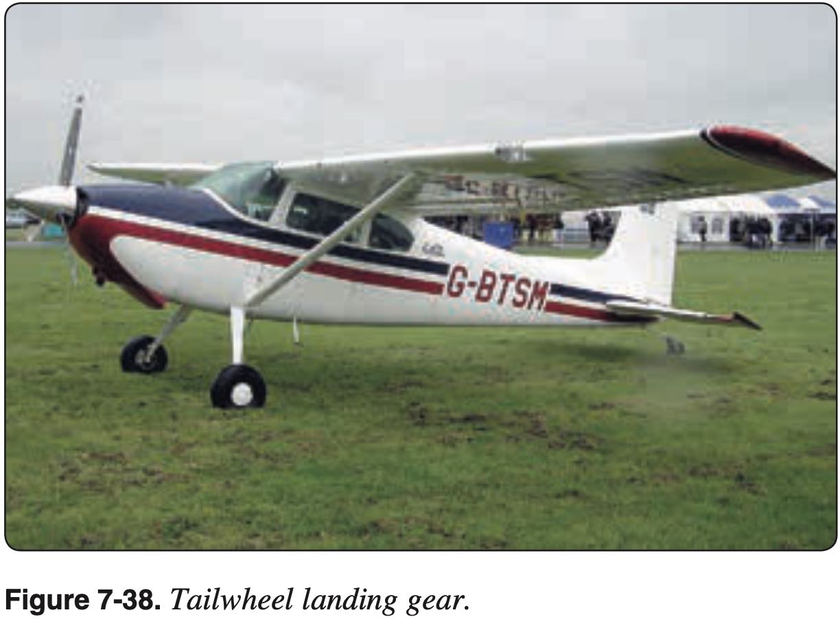
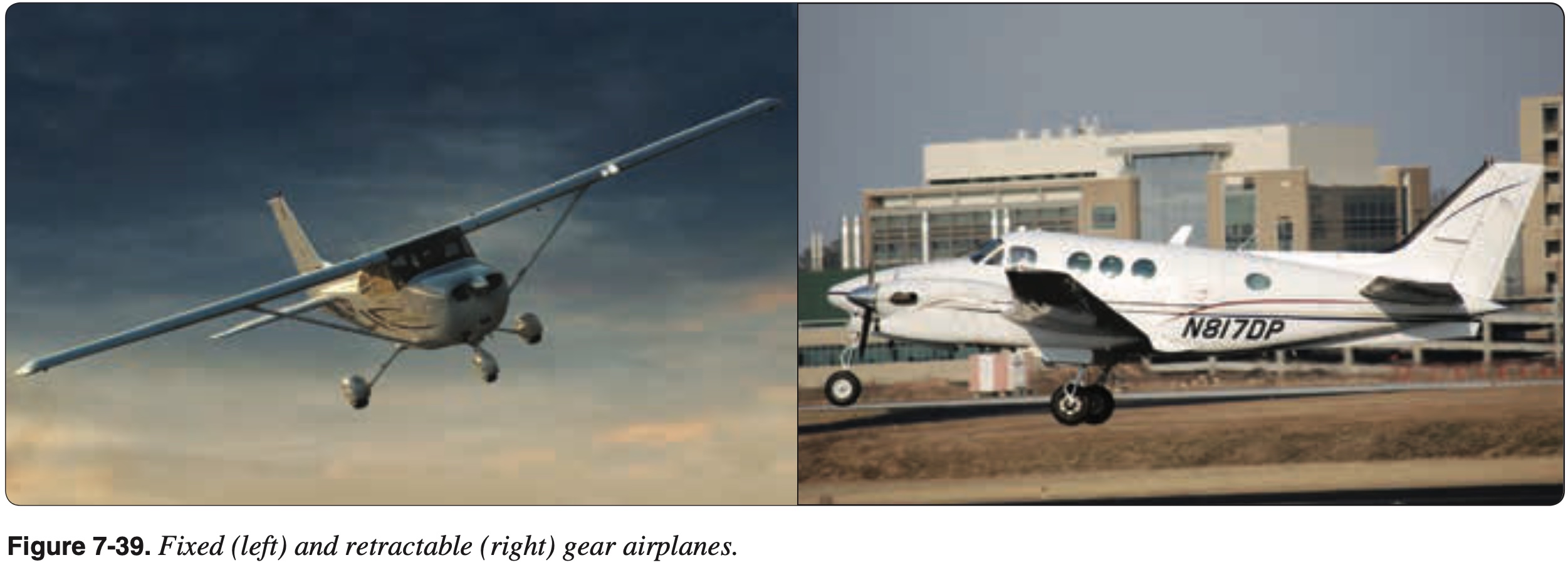
- Fixed / Retractable
- Retractable gear might be actuated by an electric motor powering a hydraulic pump, or purely electric
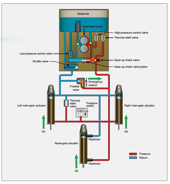
- Tricycle / tailwheel
- Tricycle advantages
- Better braking
- Better forward visibility during taxi, takeoff, landing
- Better stability during ground operations (CG in front of main wheels)
- Tricycle advantages
- Struts
- Air/oil, spring steel
- Brakes
Avionics and Autopilot
- Avionics - electronic systems used on aircraft
- Communication
- VHF
- Navigation
- VOR (VHF)
- TACAN (UHF for DME for GA)
- GPS
- Display
- Autopilot
- Bendix/King KAP 140 is 2-axis autopilot (pitch, roll)
- Reduce pilot workload
- Needs to be monitored to ensure correct operation
- Some avionics (G5) have battery backup to continue functioning even if plane's battery dies
Instructor Note
- Probably the most important thing here, especially given the diversity of avionics across many flight school's planes, is operational profficiency with the particular avionics in the plane you are flying
- Need to know how to at least perform the basics proficiently so as not to increase pilot workload during flight
- Use of radios and navigational aids
- Enter in flight plan / waypoint / destination
- Situational awareness
Pitot-Static System
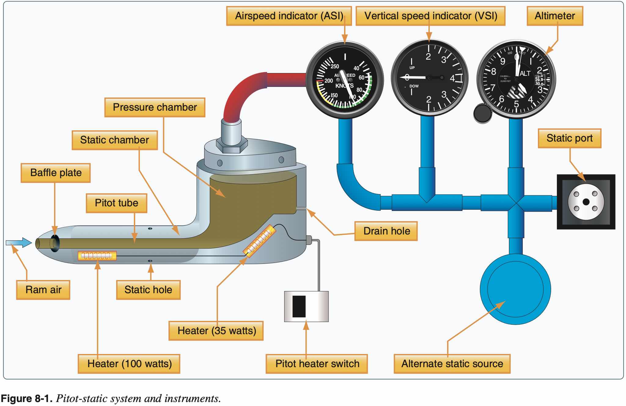
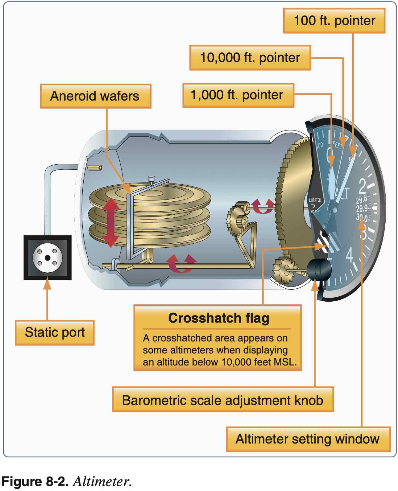
Altimeter
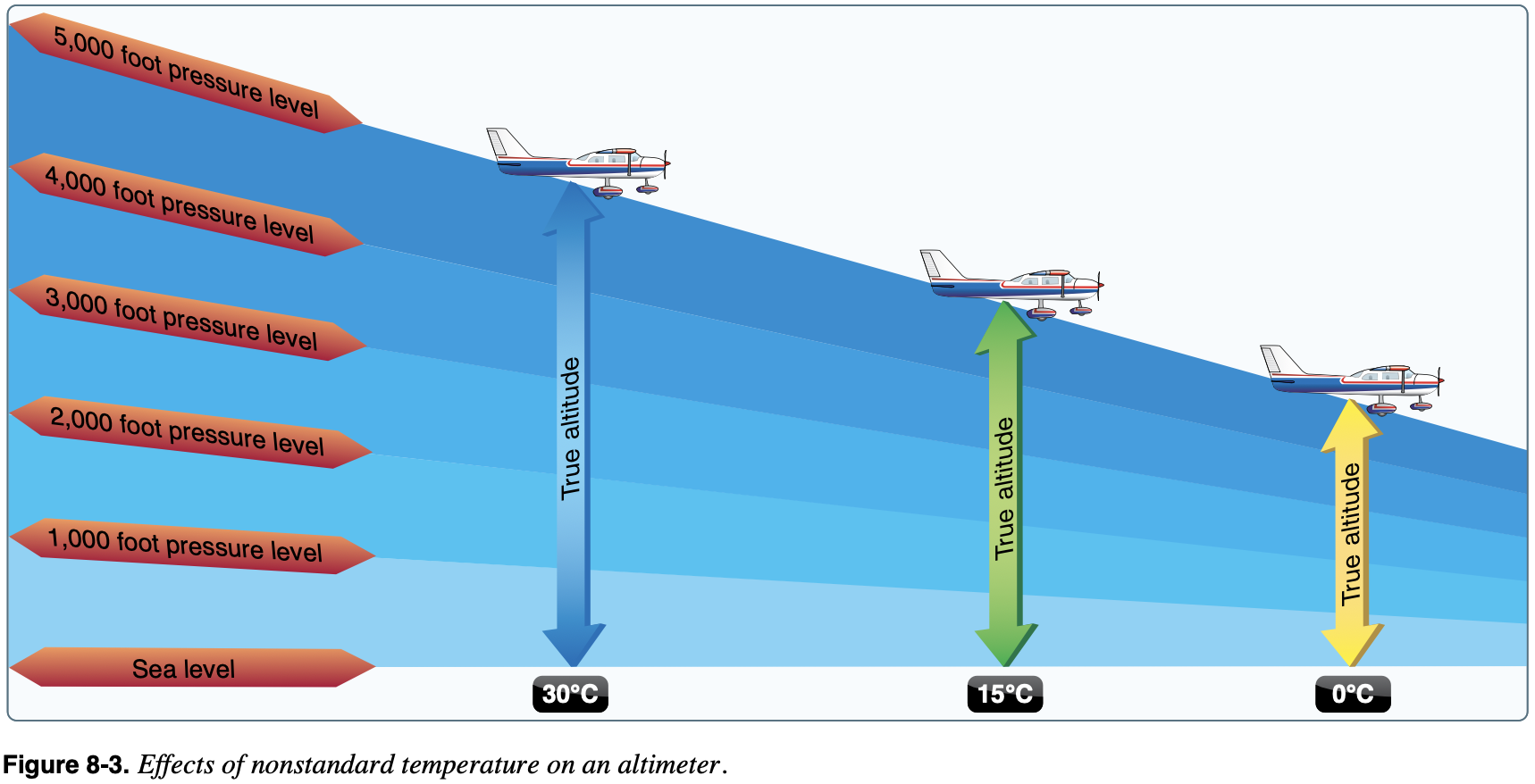
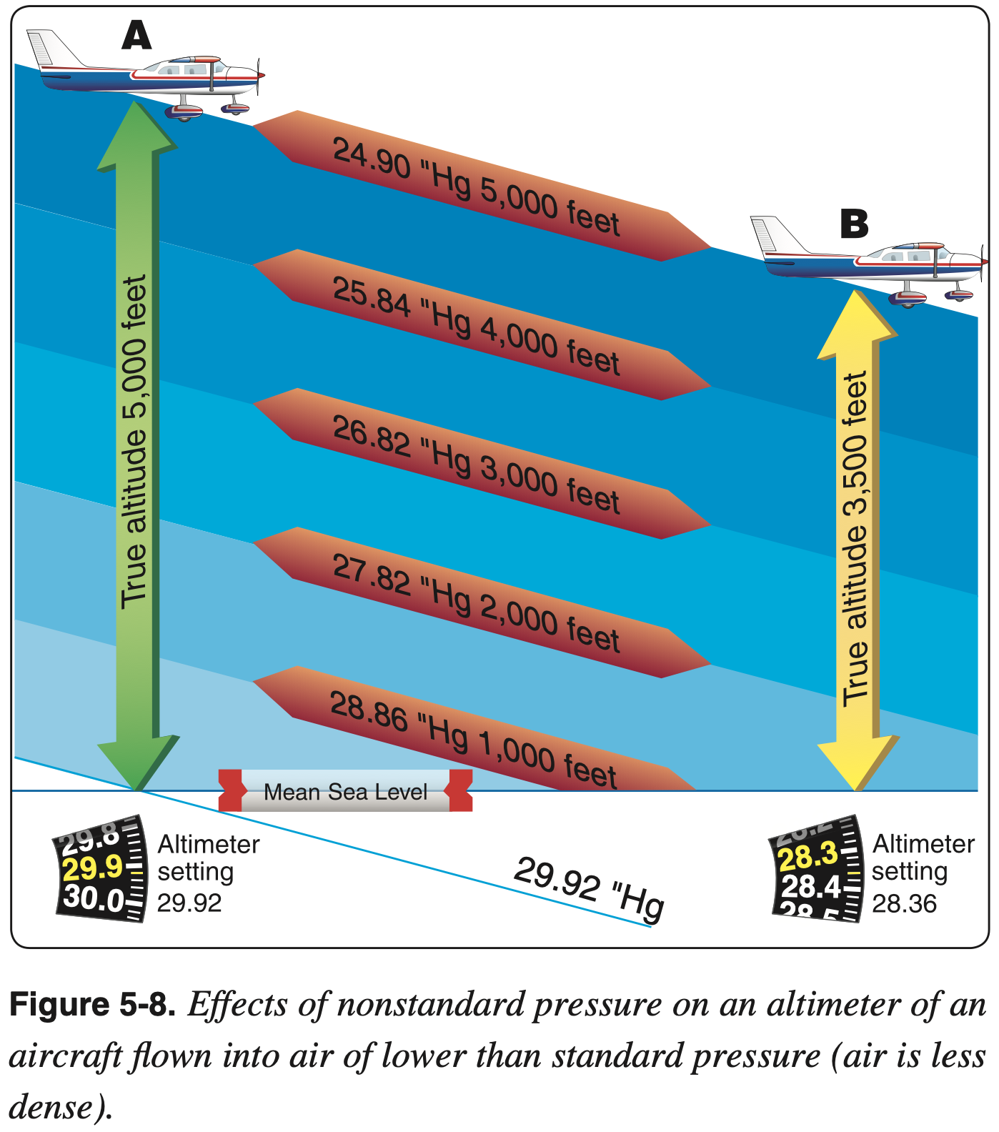
- The indicated altitude is correct, however, only when the sea level barometric pressure is standard (29.92 inHg), the sea level free air temperature is standard (15 °C or 59 °F), and the pressure and temperature decrease at a standard rate with an increase in altitude.
- Can adjust the altimeter for nonstandard pressure but not temperature
- True altitude thus varies with temperature
- Higher temps means true altitude is higher than indicated and lower temps means true altitude is lower than indicated
- Recall "hot-to-cold look out below"
- Beware obstacle clearance especially when flying in colder temps
- Mental model: altimeter setting provides true datum at ground level of the reporting station. Then consider the pressure gradient (which decreases with altitude). Compared to the standard pressure gradient, the pressure gradient in colder more dense air will decrease more quickly, and in hot air the pressure gradient will decrease less quickly.
Preflight Check
- Reads within 75 feet of field elevation when set to local altimeter setting
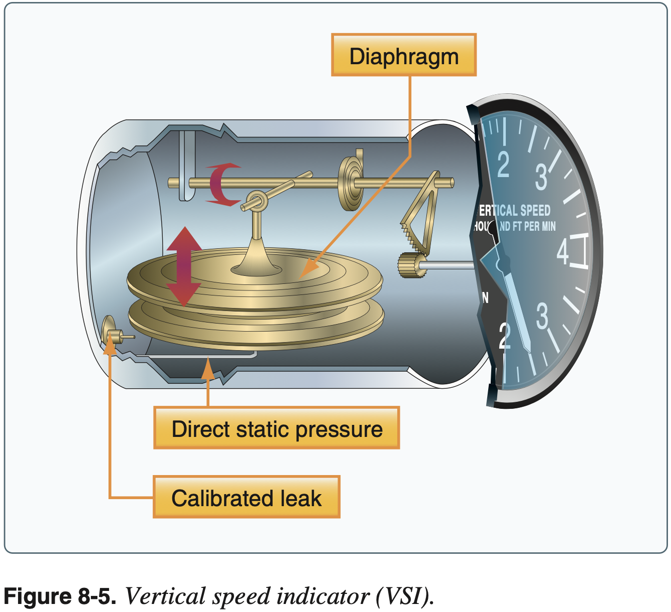
Vertical Speed Indicator (VSI)
- Not required equipment for VFR or IFR flight
- Uses static pressure only
Preflight Check
- Should indicate 0 when on the ground
- If it indicates something other than 0, this value can be used as 0 and then interpret changes from that value
- Should see a small momentary deviation from 0 when changing to alternate static source
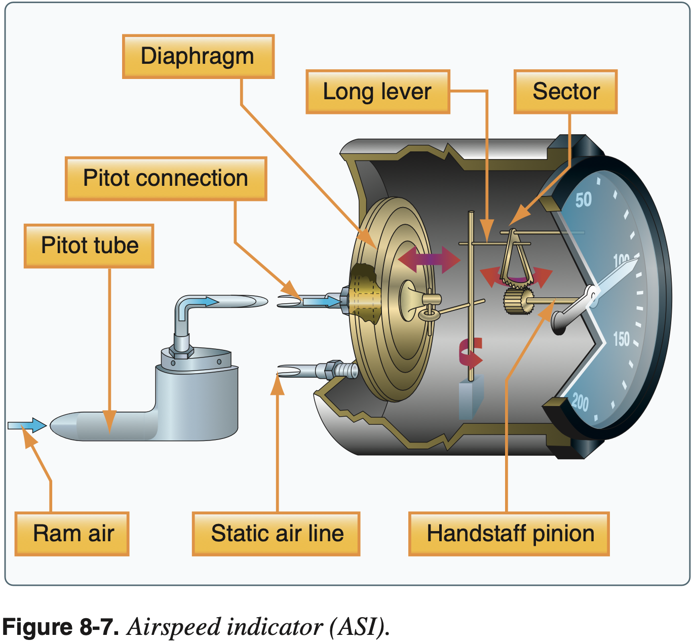
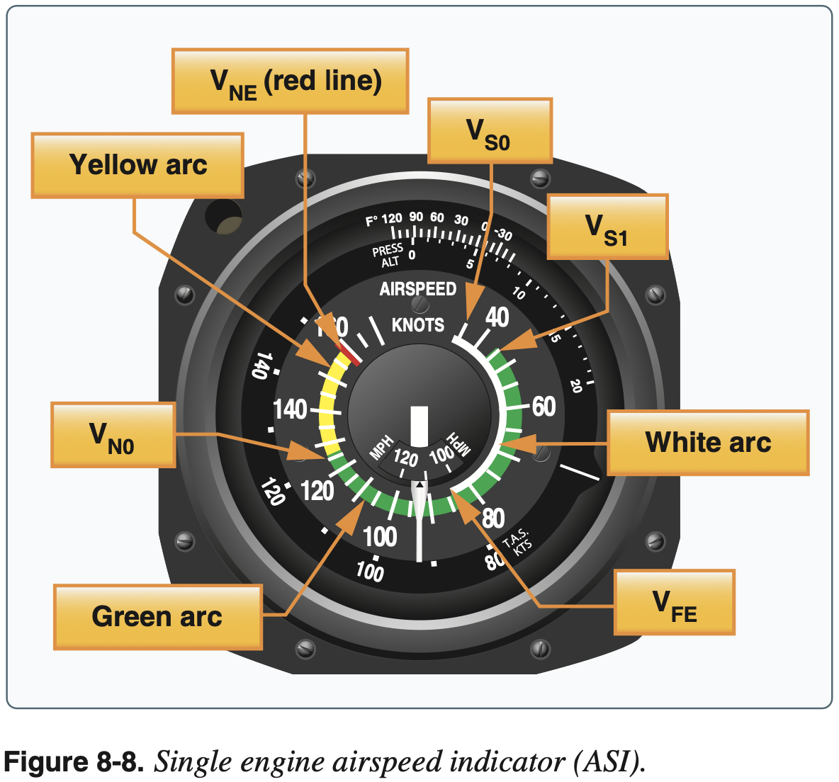
Airspeed Indicator (ASI)
- Requires pitot and static pressure
- Required for day VFR operation
- Lower limits of green and white arc are power-off stall speeds
- Other speeds not here are, for example,
, , and - The same behavior described by "hot-to-cold look out below" for the altimeter applies to the airspeed indicator as well - when flying to a warmer area, for example, true airspeed will increase (given a constant power setting and true altitude)
Preflight Check
- Should read 0 when stationary and while taxiing
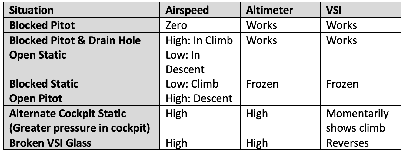
Failure modes
- Alternate static source
- Due to the venturi effect of the air flowing around the fuselage, the air pressure inside the flight deck is lower than the exterior pressure.
Static Pressure
Consider the atmosphere as an ideal gas. The moisture content in the air also affects its density.
From FAA-H-8083-25B Pilot's Handbook of Aeronautical Knowledge Chapter 8: Flight Instruments:
Adjustments to compensate for nonstandard pressure do not compensate for nonstandard temperature. Since cold air is denser than warm air, when operating in temperatures that are colder than standard, the altitude is lower than the altimeter indication.
When flying into a cooler air mass while maintaining a constant indicated altitude, true altitude is lower. If terrain or obstacle clearance is a factor in selecting a cruising altitude, particularly in mountainous terrain, remember to anticipate that a colder-than-standard temperature places the aircraft lower than the altimeter indicates. Therefore, a higher indicated altitude may be required to provide adequate terrain clearance.
When the air is warmer than standard, the aircraft is higher than the altimeter indicates.
For an incompressible fluid the hydrostatic pressure is given by the following, where
TODO@dpwiese - insert picture here so sign of
Using a reference pressure
We can differentiate to get the gradient but basically we can see that at a given height
TODO@dpwiese - insert picture showing these pressure gradients
Gyroscopic Principles
- Principles
- Rigidity in space
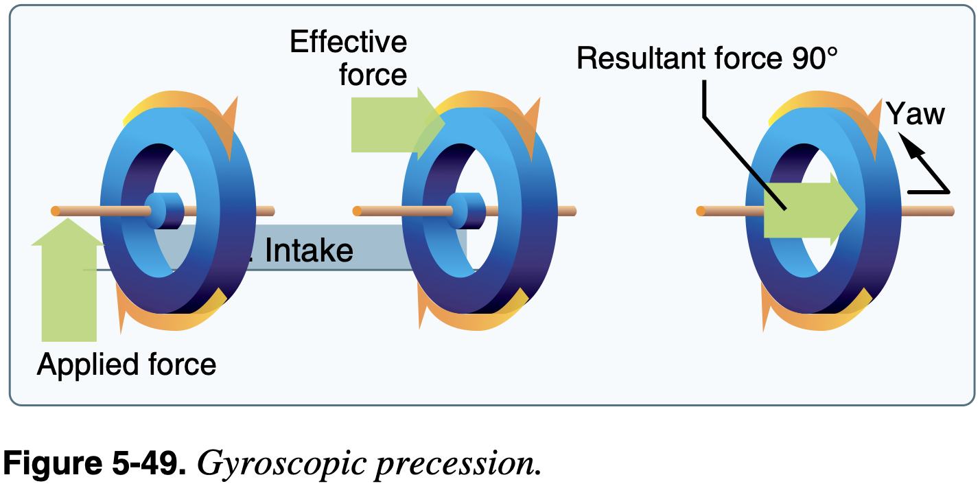
- Precession
- These principles areapplicable to understand the gyroscopic action of the propeller as well as gyroscopic instruments.
- First consider precession
- Consider a rotating disc.
- moment of momentum (or angular momentum) vector, parallel to rotation - Moment of momentum measures an objects tendency to continue to spin, it describes the rotary inertia of a system in motion about an axis.
- Apply couple (or pure moment)
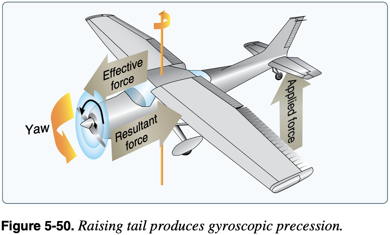
perpendicular to - Newton's second law for rotation is
, therefore the angular momentum vector is moving in the direction of - Applying this to an tailwheel aircraft rolling down the runway as it rotates, which is a common instance where this effect can be experienced
is out the nose representing the angular momentum of the spinning propellor, which is spinning clockwise from the pilot's view - A pitch down to raise the tailwheel is a couple
out the left side of the plane - Therefore
is also out of the left side of the plane, meaning the angular momentum is changing towards the left, indicating a left turning tendency
Gyroscopic Instruments
- Principles
- Rigidity in space
- Precession
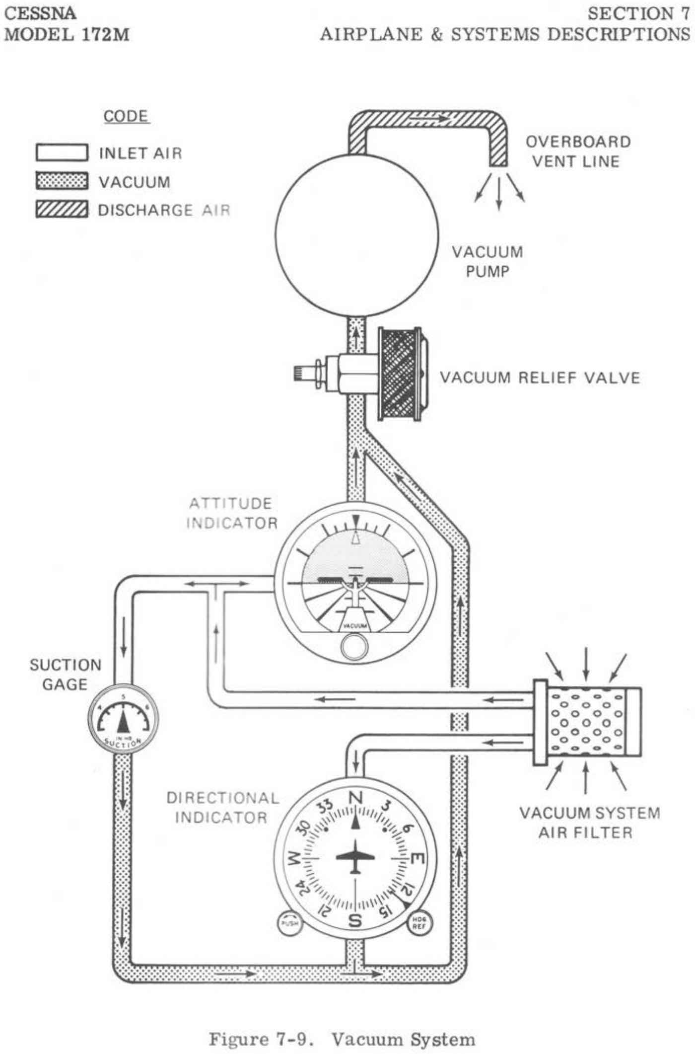
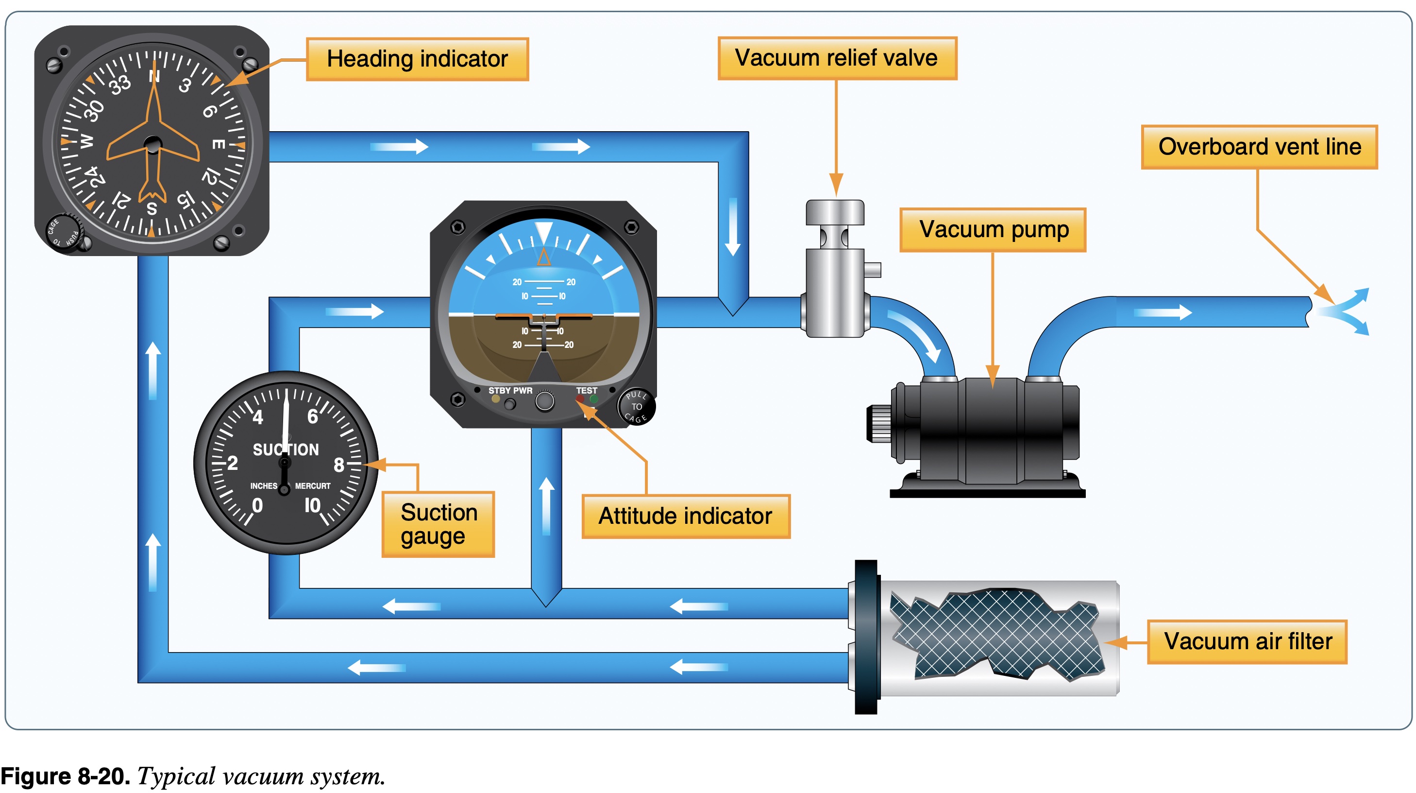
- Electrically or vacuum powered
- What is in POH might have changed and need to consult supplements, e.g. G5 attitude indicator using solid state (electrically powered) gyro instead of vacuum powered.
- Due to friction, gyroscopic instruments can drift and need to be reset periodically (for example heading indicator to compass)
- For example, check and reset every 15 minutes
- Certain gyroscopic instruments have specific pitch and bank limits that induce a tumble of the gyro.
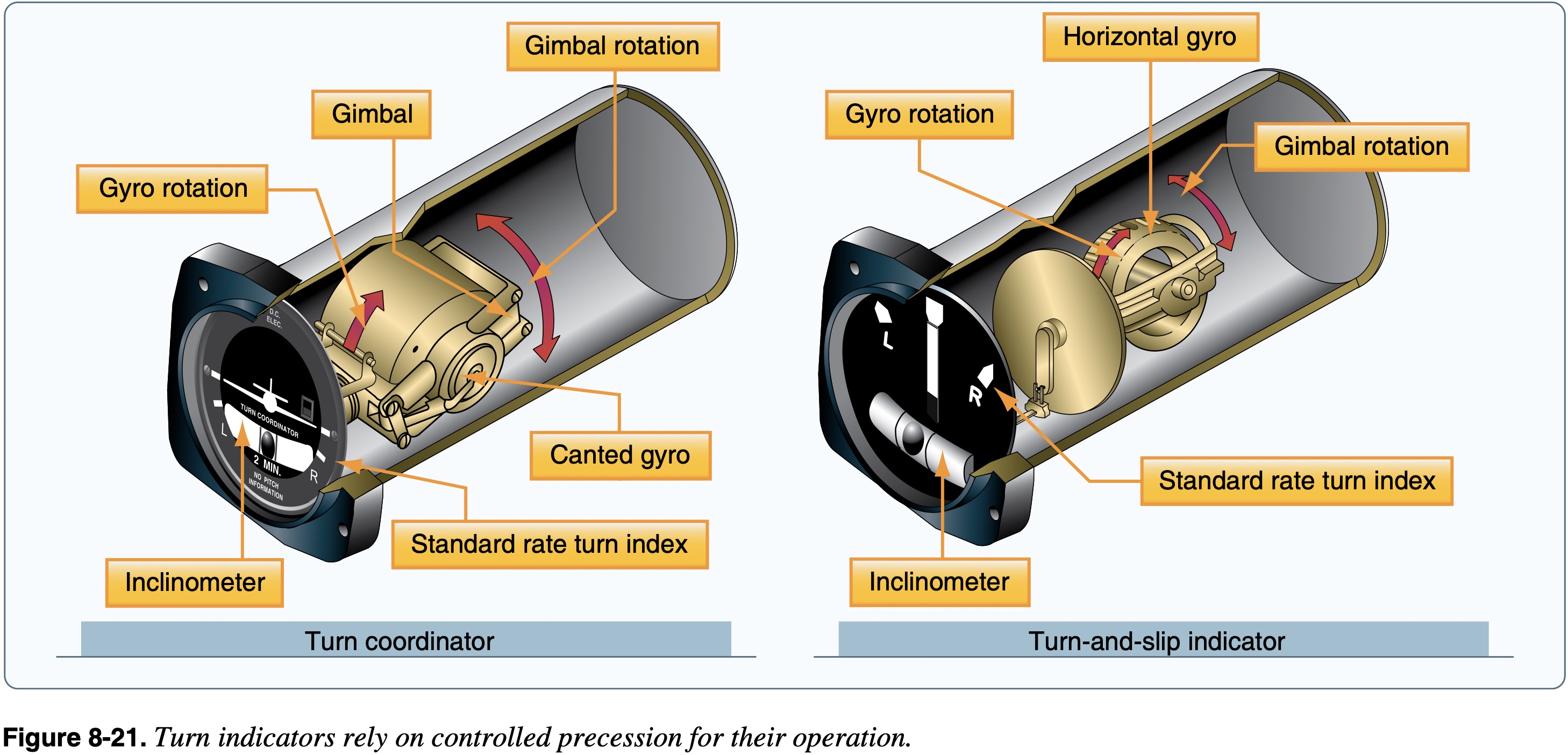
- Turn indicators
- Turn coordinator:
- Roll rate (initially)
- Rate of turn (after it stabilizes)
- Quality of turn
- Contains inclinometer - the ball - "step on the ball" to coordinate flight
- Turn and slip indicator:
- Rate of turn
- Quality of turn
- Turn coordinator:
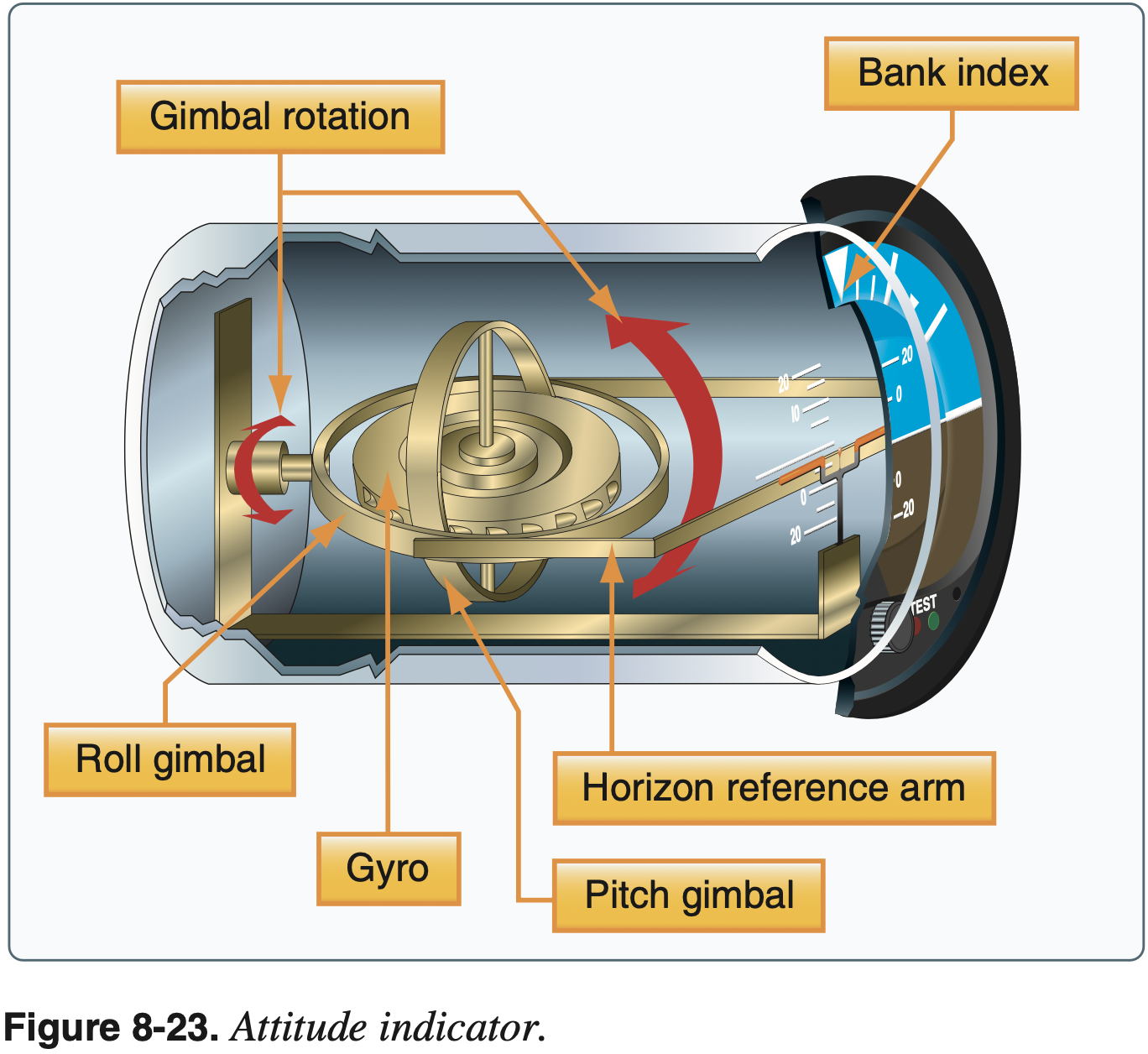
- Attitude indicator
- Also known as artificial horizon
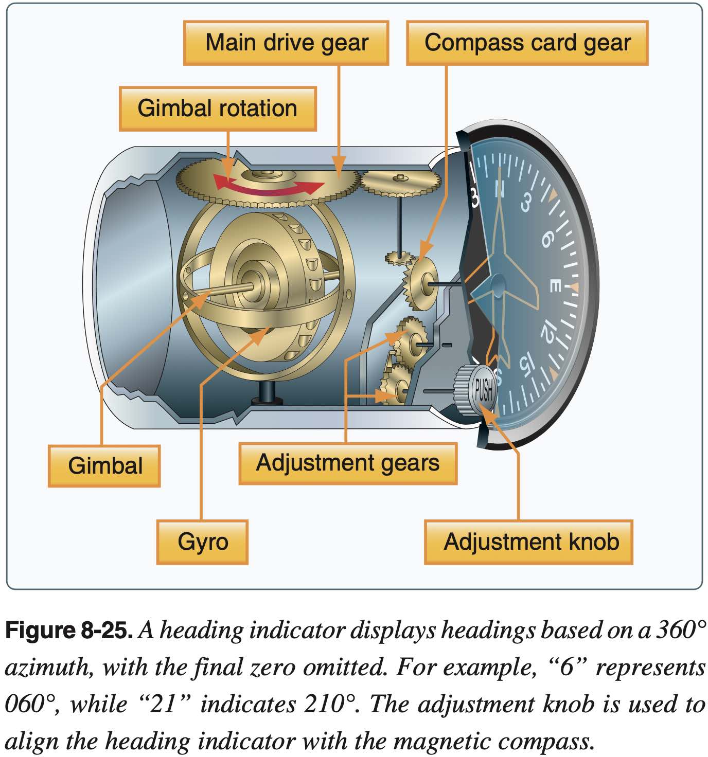
- Heading indicator
- Also known as directional gyro
- Usually powered by the aircraft vacuum system
- Errors in compass make it hard to use to turn to specific headings, especially in turbulent air - heading indicator helps with this
- Some heading indicators referred to as horizontal situation indicators (HSI) receive a magnetic north reference from a magnetic slaving transmitter and generally need no adjustment.
- See also: remote indicating compass
- Radio magnetic indicator (RMI)
- A standard-rate turn is defined as a turn rate of 3° per second (2 minutes to complete a 360 degree turn).
Environmental System
- Environmental systems are those which are responsible for maintaining pilot and passenger comfort, and to ensure the human body can properly function physiologically
- Heating / Air Conditioning
- Heating systems use shroud around exhaust to capture waste heat, or require the separate burning of fuel to heat the cabin
- Read your planes POH/AFM to learn about its specific heating system
Deicing and Anti-icing
Airframe
- Wings
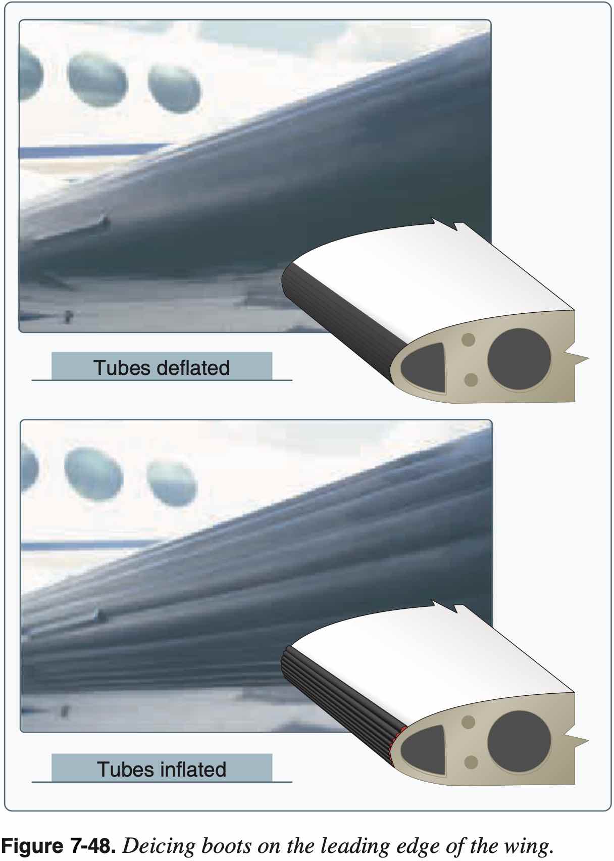
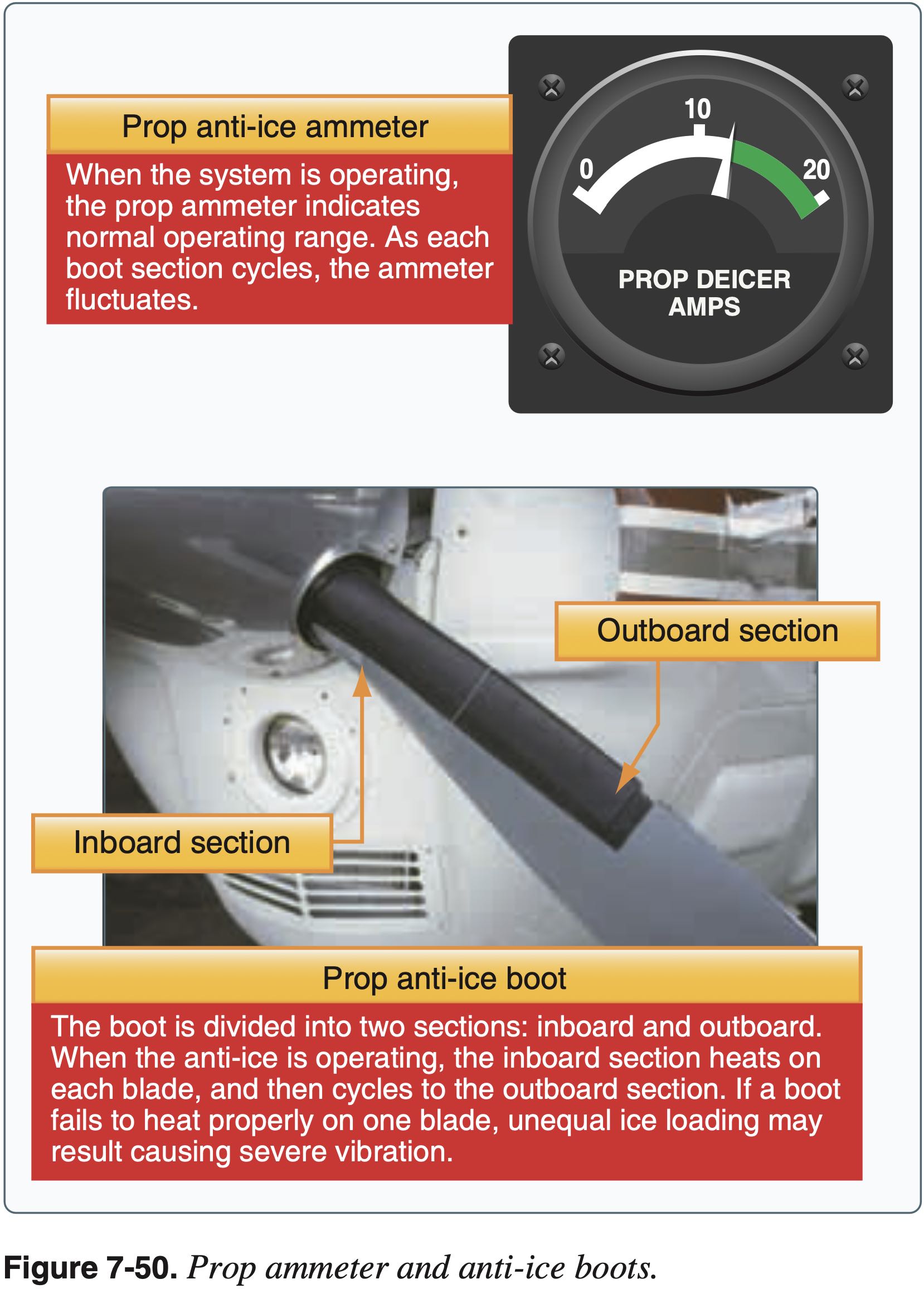
- Boots
- Use as soon as icing is observed
- Heated leading edge
- Also called "hot wing"
- Uses hot air from turbine compressor, for example
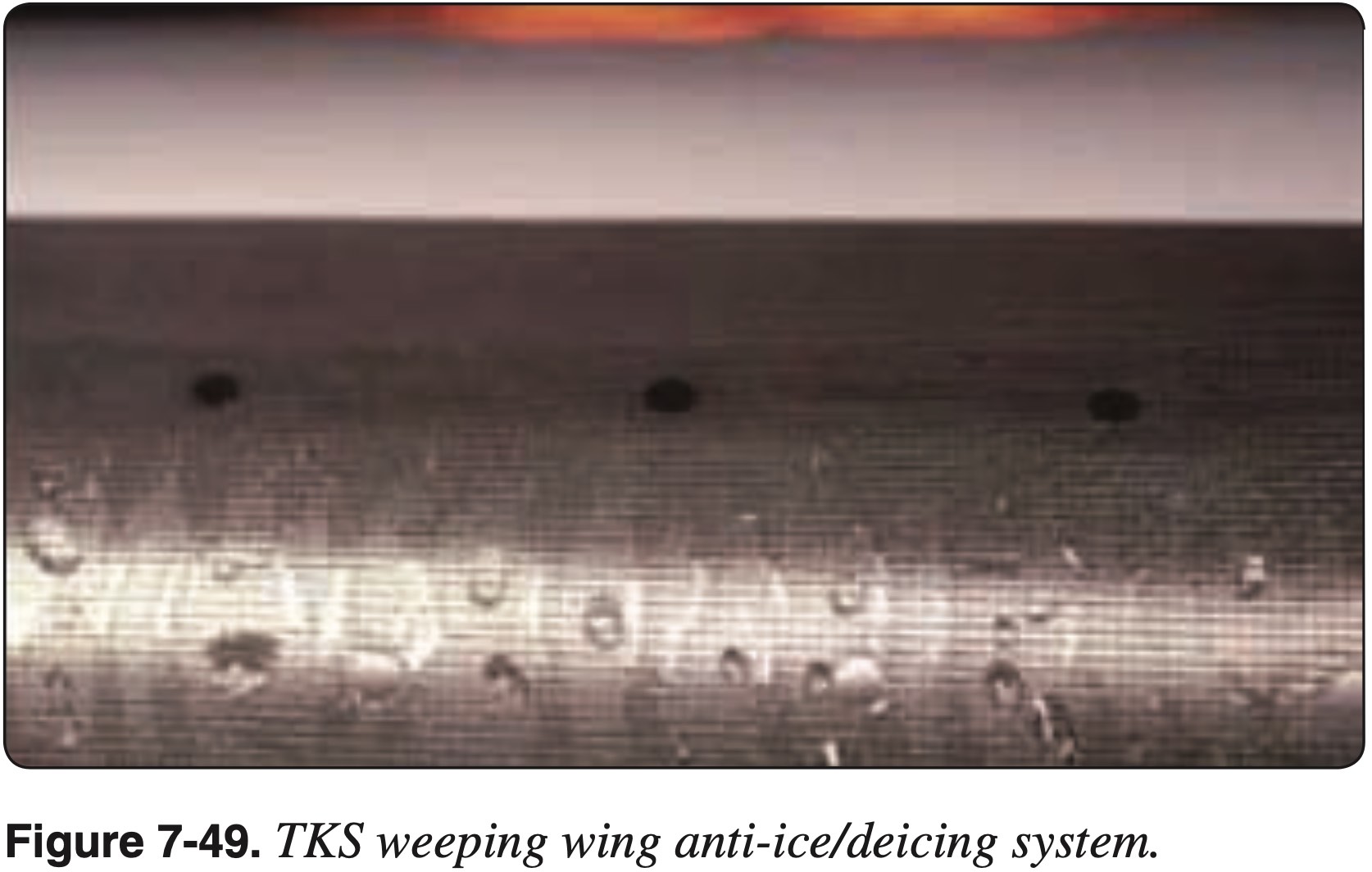
- Weeping wing
- Deicing fluid (e.g. TKS fluid, like antifreeze) comes out of small holes in leading edge
- TKS (Tecalemit-Kilfrost-Sheepbridge Stokes) was the name of a British aerospace company during WWII that developed the original weeping wing technology
- Boots
- Windscreen
- Alcohol
- Hot air defrost
- Electric (like rear window of car)
- Icing fluid from prop in single engine also sprays back on windscreen
Propellor or Rotor
- Propellor
- Alcohol
- Electric heating element
- Boots
Air Intake
- Carb heat
- Spring-loaded air-filter bypass door
- Alternate air
Fuel System
- Check for water in fuel during preflight
Pitot-Static System
- Pitot heat
- Alternate static source
Encountering Icing
- Exit area of icing
- Generally climb
- To find temps colder than -20 °C
- Being higher gives more options
- Alternatively descend to find temperatures warmer than 5 °C
- Gentle maneuvers
- Avoid increasing load factor too much
- Fly faster
- Avoid configuration change
- No flaps to avoid tailplane stall
Icing Regulations
Known icing conditions
- Note: Part 91 was updated since this letter to include 14 CFR §91.527
"Known icing conditions" involve instead circumstances where a reasonable pilot would expect a substantial likelihood of ice formation on the aircraft based upon all information available to that pilot.
Whether a pilot has operated into known icing conditions contrary to any limitation will depend upon the total information available to the pilot, and his or her proper analysis of that information in evaluating the risk of encountering known icing conditions during a particular operation.
Atmospheric conditions in which the formation of ice is observed or detected in flight. Note-Because of the variability in space and time of atmospheric conditions, the existence of a report of observed icing does not assure the presence or intensity of icing conditions at a later time, nor can a report of no icing assure the absence of icing conditions at a later time.
Oxygen System
- In a mixture of gases, each constituent gas has a partial pressure which is the notional pressure of that constituent gas as if it alone occupied the entire volume of the original mixture at the same temperature.
- Components
- Mask/cannula
- Supply (bottle/air bleed)
- Regulator
- For optimum protection, pilots are encouraged to use supplemental oxygen above 10,000 feet cabin altitude during the day and above 5,000 feet at night.
- Most regulators provide 100% cabin air at around 8,000 ft, and 100% oxygen at 34,000 ft, with the ratio changing in between.
- Be aware of the danger of fire when using oxygen
- Masks
- Face worn mask or cannula
- Most masks are the oronasal type that covers only the mouth and nose
- Cannula only goes in nose. More comfortable, but is not as reliable at providing adequate oxygen.
- Current regulations require aircraft with oxygen systems installed and certified for operations above 18,000 feet to be equipped with oxygen masks instead of cannulas.
- Oxygen delivery systems
- Diluter-Demand
- Supply oxygen only when the user inhales through the mask
- Used up to 40,000 ft
- Pressure-Demand
- Supply oxygen to mask at positive pressure above 34,000 ft
- Used above 40,000 ft
- Continuous-Flow
- Most common kind in general aviation aircraft
- Usually provided for passengers
- Electrical Pulse-Demand
- provide oxygen flow during the initial portion of inhalation
- do not waste oxygen during the breathing cycle
- reduce oxygen 50-85 percent compared to continuous-flow
- Diluter-Demand
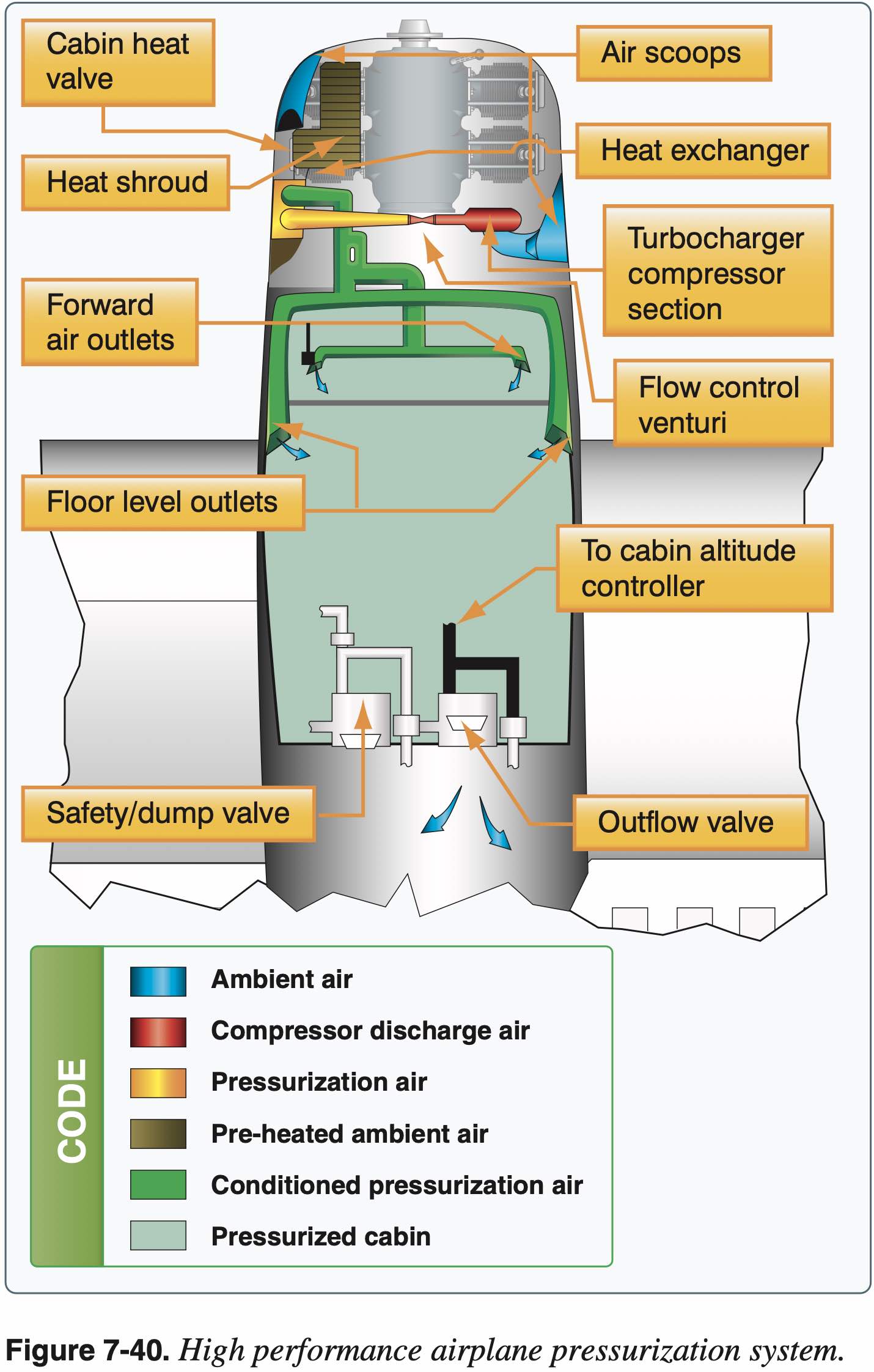
Pressurization
- Aircraft more efficient at altitude
- Can help avoid bad weather
- Cabin pressure typically maintained at 8,000 feet
- Pressurized air from turbine compressor or turbocharger used to pressurize aircraft
- Cabin and baggage compartments pressurized
- Differential pressure puts stress on airframe
- Decompression
- Rapid / explosive
- Dangers
- Hypoxia
- Gas decompression sickness (nitrogen bubbles out of blood)
- Relief valve
- Gauges to monitor pressure
- Cabin, flight, and baggage compartments are incorporated into a sealed unit capable of containing air under a differential pressure.
- Maximum differential pressure varies by airplane - be familiar with limitations
- Turbine-powered aircraft-bleed air from engine compressor section used to pressurized
- Light aircraft-turbocharger's compressor/engine-driven pneumatic pump used to pressurize. Compression heats the air, so it's routed through a heat exchange unit before entering the cabin.
- Provides pressure regulation, pressure relief, and vacuum relief, as well as the means for selecting the desired cabin altitude.
- Uses a cabin pressure regulator, an outflow valve, and a safety valve.
- Cabin pressure regulator (CPR)-controls cabin pressure.
- If we reach the maximum difference, an increase in outside altitude will result in an increase inside.
- Outflow valve-keeps pressure constant by regulating flow of compressed air.
- Safety valve-combination of a pressure relief, vacuum relief, and a dump valve.
- Pressure relief-prevents cabin pressure from exceeding a predetermined differential pressure above ambient pressure. Vacuum relief-prevents ambient pressure from exceeding cabin pressure by allowing external air to enter when ambient pressure exceeds cabin pressure.
- Dump valve-dumps cabin air to atmosphere.
- Cockpit switch.
- Cabin differential pressure gauge-indicates the difference between inside and outside pressure.
- Cabin altimeter-shows altitude inside the airplane. Differential pressure gauge and cabin altimeter could be combined into one instrument.
- Cabin rate of climb/descent.
System Abnormalities or Failures
- Indications of system abnormalities or failures
- Managing system abnormalities or failures
Inoperative Equipment Overview
When thinking about what equipment is required first think of 14 CFR §91.7 - Civil aircraft airworthiness that says:
No person may operate a civil aircraft unless it is in an airworthy condition. The pilot in command of a civil aircraft is responsible for determining whether that aircraft is in condition for safe flight
So if you have any reason to think the aircraft is not safe to fly due to some inoperative equipment, don't fly it.
Regulations should be a floor for safety not a ceiling.
Minimum Equipment List (MEL)
- A minimum equipment list is a list of equipment approved by the manufacturer and the FAA, by which you may legally operate a flight with inoperative equipment.
- Requirements below are when an aircraft needs an MEL
- No aircraft can fly with inoperative equipment unless it has an approved minimum equipment list (MEL)
- Exception:
- Non-turbine planes (and some other aircraft) as long as the inoperative equipment is not required by 14 CFR §91.205
- And not required by type certificate or Airworthiness Directive (AD)
- Marked as "INOP"
- If the aircraft does not have an MEL can follow 14 CFR §91.213 which says for non-turbine planes (and some other aircraft) as long as the inoperative equipment is not required by 14 CFR §91.205 and not required by type certificate or Airworthiness Directive (AD) it can be marked as "INOP" and the aircraft can still be flown.
- If missing any items in MEL must get authorization from FSDO
Kind of Operations (Equipment) List (KOL or KOEL)
- Indicates equipment required for airworthiness during the kinds of operations (e.g. VFR/IFR, day/night)
- The Cessna 172SP, for example, which contains a KOEL in Section 2 of the POH indicates that strobes are required for all flight conditions.
- If our aircraft has a KOEL it will be in the POH?
- Indicates equipment required for airworthiness during the kinds of operations (e.g. VFR/IFR, day/night)
Comprehensive Equipment List (CEL)
- For example in the weight and balance section of C172SP POH
- It is a comprehensive list of equipment in the aircraft and identifies those items that are required by CFRs for FAA certification
- Is this actually any different than the minimum required by FAA? Or is Cessna imposing additional requirements beyond the FAA with this list?
- Is this the same as KOEL?
Supplemental Type Certificate (STC)
- FAA authorization to modify aircraft (e.g. install new avionics)
- Might come with additional requirements, e.g. keep PFD manual in plane
This has interesting discussion about what equipment needs to be working in particular on intermittently working equipment Minimum Equipment: What Has to be Working?
A good way to approach required equipment on the aircraft is to think through a hypothetical situation of preflighting an aircraft prior to a flight, finding a piece of equipment inoperative, and then determining whether or not the aircraft can still be flown with said equipment inoperative.
Determining Airworthiness
- The following flowchart captures most of the questions that need to be answered in this situation.
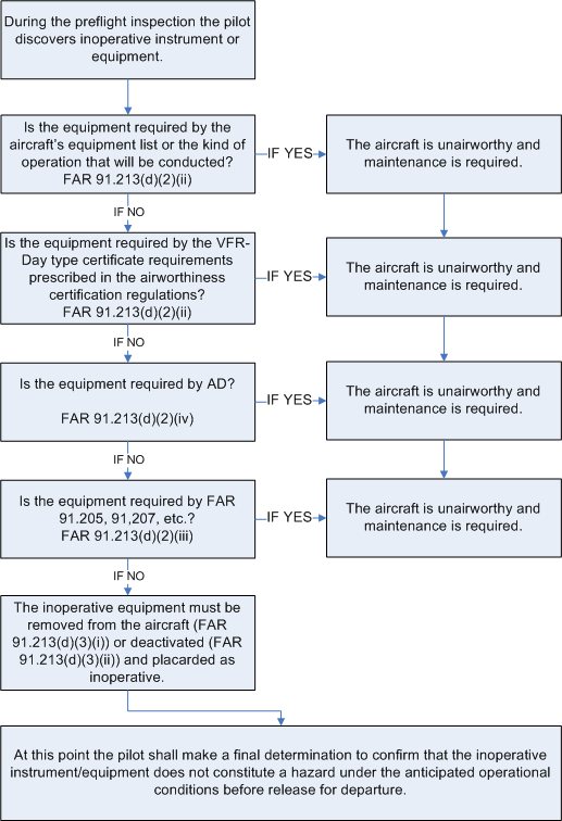
- The following list is similar to the questions in the flowchart.
- The order in which these questions are asked does not matter.
- Does the plane have an MEL?
- Minimum equipment list, approved by FAA
- General aviation planes will almost certainly not have an MEL
- Does the plane have a KOEL (kinds of equipment list)?
- G1000/nav com III POHs do, start there (section 2 POH, operating limitations)
- Does the plane have a CEL (comprehensive equipment list)?
- 172R/S/M/N/P (section 6 POH, weight and balance, R required for flight, S standard)
- Is it required by 14 CFR §91?
- 14 CFR §91.205, 14 CFR §91.207, etc.?
- A+TOMATOFLAMES, FLAPS, etc.
- Is it required by Airworthines Directive?
- Is it required by STC?
- Finally, is it required to fly safely?
- See 14 CFR §91.7
- Does the plane have an MEL?
- If it legal to fly with the inoperative equipment, it must be placarded and either removed or deactivated, if it is removed, a new weight and balance might need to be computed depending on the weight of the part.
FAA-AC-91-67A Minimum Equipment Requirements for General Aviation Operations Under FAR Part 91
Deactivation. When an item is "deactivated" or "secured," or both, the specified item must be put into an acceptable condition for safe flight. Deactivation may involve more than simply turning off a system switch, which does not remove power from the system. Deactivation may involve pulling and securing the circuit breaker and/or removing the equipment. Deactivation of an inoperative system is not preventive maintenance as described in part 43 appendix A. Regardless of the method of deactivation, a person authorized to approve the aircraft for return to service under § 43.7 must make the maintenance record entry required by § 43.9. No person may operate the aircraft without the entry required by § 43.9.
The safest interpretation of this is that deactivation is not preventative maintenance and therefore not something the pilot can do.
However, the references below may offer other interpretations that might be applied in the case of pulling and securing a circuit breaker in order to deactivate a piece of equpiment.
Specifically, that the act of pulling a circuit breaker, like adding oil to the engine, doesn't even rise to the level of preventative maintentance.
Many preventive maintenance tasks are listed in 14 C.F.R. part 43, appendix A, paragraph (c). The paragraph sets forth in 32 numbered subparagraphs items the FAA has determined to be preventive maintenance. Even though the introductory text of subparagraph (c) states that "[p]reventive maintenance is limited to the following work ...." (emphasis added), in view of the broader definition of preventive maintenance in section 1.1, we believe that such limitation is not controlling. Similarly, for the same reason, we also believe that the following sentence in Advisory Circular 43-12A, Preventive Maintenance (which was referenced in Mr. Hernandez's letter), is overly restrictive That sentence, found in Paragraph 3(b)(l), states: "If a task or maintenance function does not appear in the list, it is not preventive maintenance." As with the other paragraphs of Appendix A (i.e., on major repairs and major alterations), the lists are better viewed as examples of the tasks in each category-they cannot be considered all-inclusive. There are, no doubt, many "simple or minor preservation operations [tasks]" and many "replacement[s] of small standard parts not involving complex assembly operations" performed daily, especially on small general aviation aircraft, that the agency would consider to be preventive maintenance, though they are not included in the 32 listed items.
- Referenced above in Pilot Performed Preventative Maintenance
- In the context of pilots deactivating inoperative systems (e.g. via pulling and securing a circuit breaker) this letter offers some guidance related to things pilots can do which do not even rise to the level of preventative maintenance.
- In the context of this letter, it seems a reasonable position to take that pulling and securing a circuit breaker is the same level as adding oil, and therefore while not preventative maintenance something the pilot can legally do.
14 CFR §91.213(d)(3) also says, "if deactivation of the inoperative instrument or equipment involves maintenance" implying that deactivation may be possible that does not involve maintenance.
Finally, remember about Advisory Circulars from the AIM:
Advisory Circulars ‐ The FAA issues Advisory Circulars (AC) to inform the aviation public in a systematic way of nonregulatory material. Unless incorporated into a regulation by reference, the contents of an advisory circular are not binding on the public.
Aside: a Single Broken Strobe Light
Regarding equipment required by 14 CFR §91.205, it is interesting to note that 14 CFR §91.205(b)(11) says, regarding anticollision light system:
In the event of failure of any light of the anticollision light system, operation of the aircraft may continue to a location where repairs or replacement can be made.
So this is why according to the C172SP KOEL that Strobes are required during all flight conditions.
See also Letts 2017 Legal Interpretation.
Aside: Altimeter Accuracy
Altimeter accuracy requirements +/- 75 ft. for IFR. For VFR not explicitly stated, but it's up to PIC to determine the aircraft is in a safe condition for flight.
Accuracy requirements of altimeter AIM 7-2-3 Altimeter Errors:
If the difference from the known field elevation and the altitude read from the altimeter is plus or minus 75 feet or greater, the accuracy of the altimeter is questionable and the problem should be referred to an appropriately rated repair station for evaluation and possible correction.
From 14 CFR §91.217(a)(2):
- The difference between the automatic reporting output and the altitude displayed at the altimeter shall not exceed 125 feet.