Aircraft Systems
This page covers Task A. Aircraft Systems Related to Instrument Flight Rules (IFR) Operations from the FAA-S-ACS-8C Instrument Rating Airplane Airman Certification Standards.
Objective
To determine the applicant exhibits satisfactory knowledge, risk management, and skills associated with anti-icing or deicing systems, and other systems related to IFR flight.
Deicing and Anti-icing
Airframe
- Wings
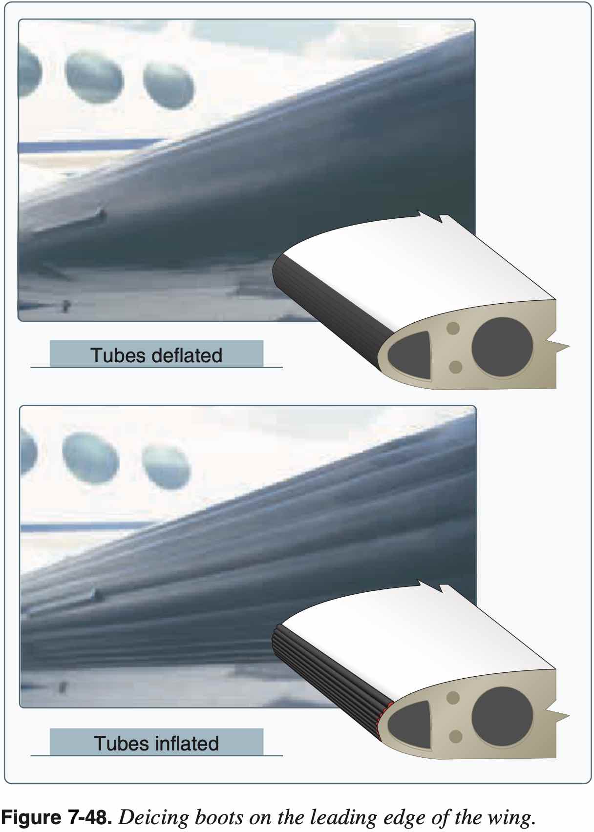
- Boots
- Use as soon as icing is observed
- Heated leading edge
- Also called "hot wing"
- Uses hot air from turbine compressor, for example
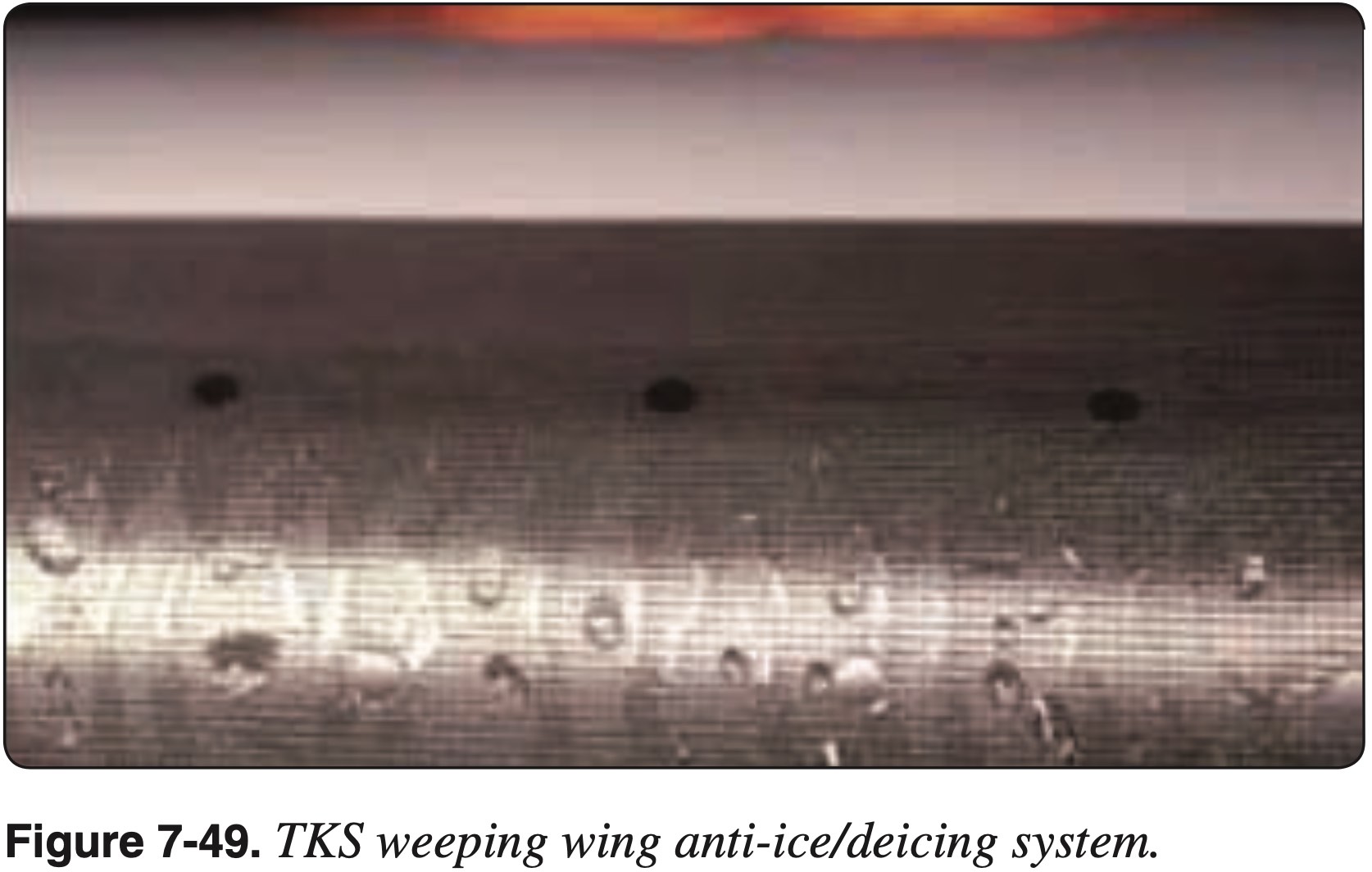
- Weeping wing
- Deicing fluid (e.g. TKS fluid, like antifreeze) comes out of small holes in leading edge
- TKS (Tecalemit-Kilfrost-Sheepbridge Stokes) was the name of a British aerospace company during WWII that developed the original weeping wing technology
- Boots
- Windscreen
- Alcohol
- Hot air defrost
- Electric (like rear window of car)
- Icing fluid from prop in single engine also sprays back on windscreen
Propellor or Rotor
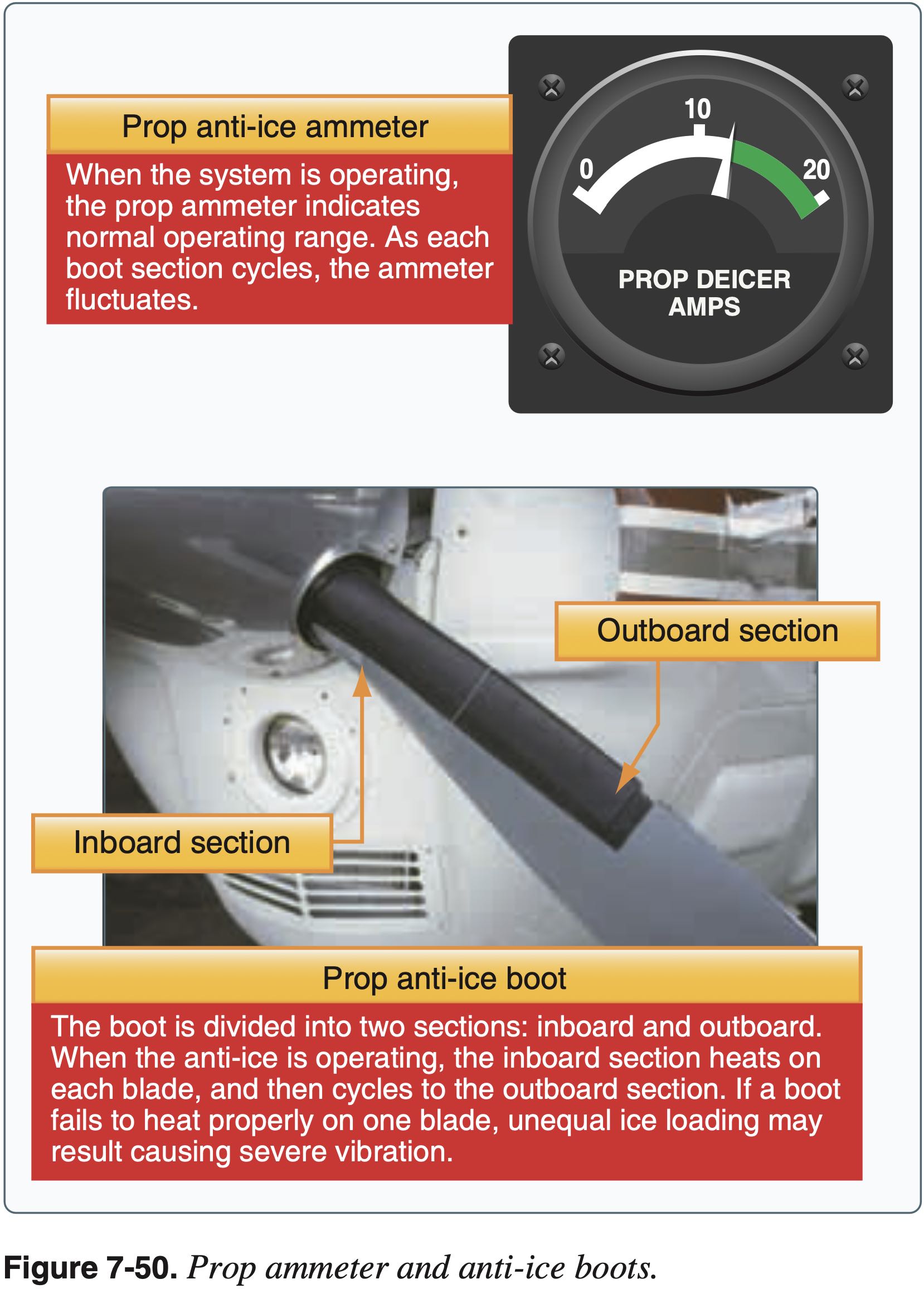
- Propellor
- Alcohol
- Electric heating element
- Boots
Air Intake
- Carb heat
- Spring-loaded air-filter bypass door
- Alternate air
Fuel System
- Check for water in fuel during preflight
Pitot-Static System
- Pitot heat
- Alternate static source
Encountering Icing
- Exit area of icing
- Generally climb
- To find temps colder than -20 °C
- Being higher gives more options
- Alternatively descend to find temperatures warmer than 5 °C
- Gentle maneuvers
- Avoid increasing load factor too much
- Fly faster
- Avoid configuration change
- No flaps to avoid tailplane stall
Icing Regulations
Known icing conditions
- Note: Part 91 was updated since this letter to include 14 CFR §91.527
"Known icing conditions" involve instead circumstances where a reasonable pilot would expect a substantial likelihood of ice formation on the aircraft based upon all information available to that pilot.
Whether a pilot has operated into known icing conditions contrary to any limitation will depend upon the total information available to the pilot, and his or her proper analysis of that information in evaluating the risk of encountering known icing conditions during a particular operation.
Atmospheric conditions in which the formation of ice is observed or detected in flight. Note-Because of the variability in space and time of atmospheric conditions, the existence of a report of observed icing does not assure the presence or intensity of icing conditions at a later time, nor can a report of no icing assure the absence of icing conditions at a later time.
Primary flight controls
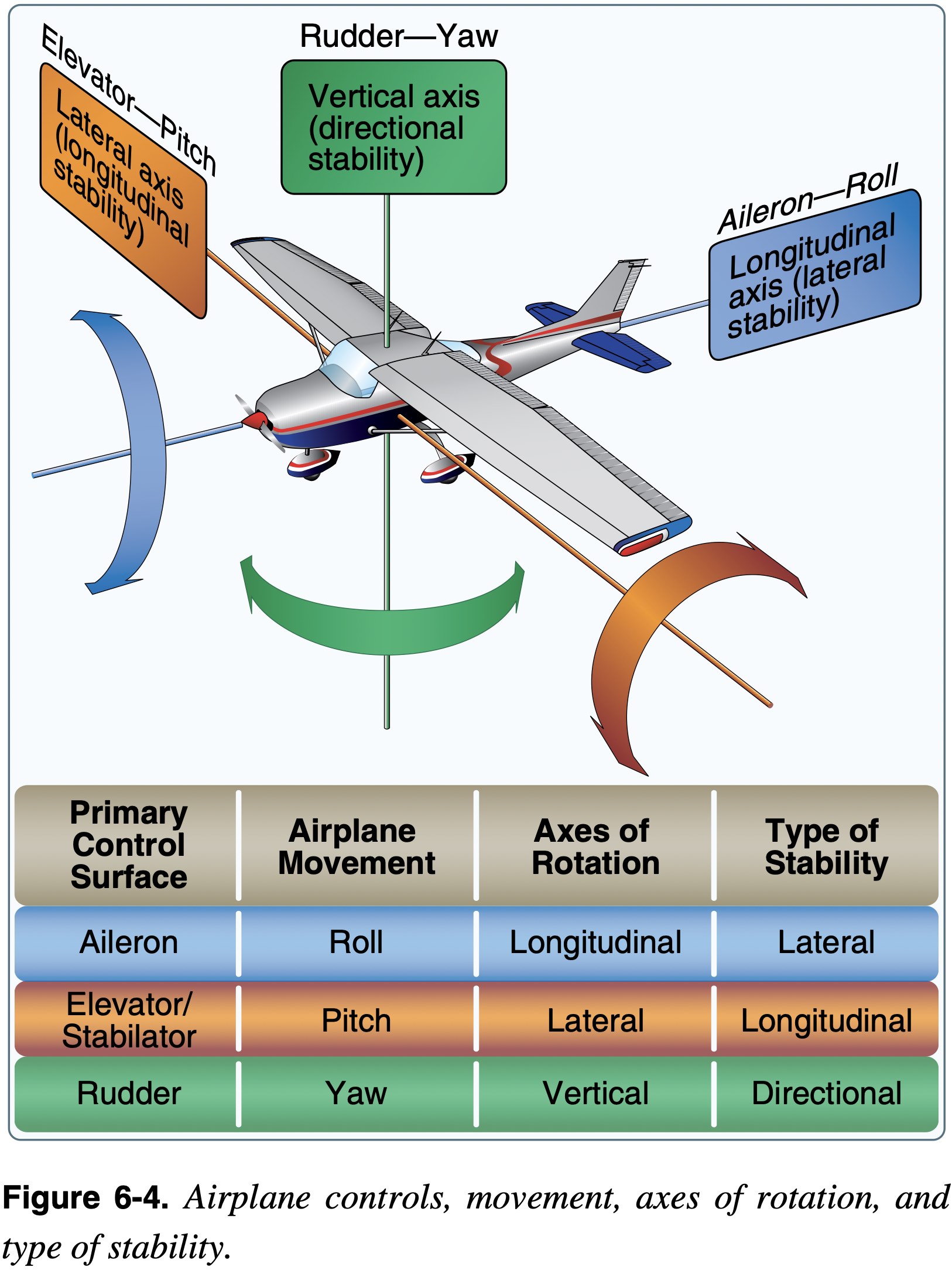
Primary Flight Controls
Control the surfaces to create the moments to rotate an aircraft about its three axes of rotation.
- Airplanes are maneuvered by changing the direction of lift.
- There are three axes about which moments are applied and the aircraft rotates.
- Different primary flight control surfaces
- Elevator
- Aileron
- Rudder
- More
- V-tail
- Stabilator
- Different primary flight control surfaces
Adverse Moments
- Control surfaces intended to induce moments about one particular axis often also induce moments about other axes as well
- For example, with the vertical stabilizer being offset above the aircraft's longitudinal access, deflection of the rudder, while it primarily induces a yawing moment also induces a rolling moment
- Adverse yaw is the term used to describe the yawing moment that typically accompanies deflection of the ailerons
- For exampe, to roll to the right the left aileron must deflect downwards
- This downward deflection, used to increase the left on the left wing, also creates additional drag and therefor a yawing moment to the right, opposite the direction of turn
- This is why coordination of ailerons and rudders is important
- Differential ailerons are a design choice used to reduce this effect by reducing the downward aileron deflection relative to the upward deflection.
- The Piper Archer uses differential ailerons
Secondary Flight Controls
Secondary Flight Controls
Those which are not considered primary and are used to change the aircraft's performance, or reduce the amount of control a pilot has to use.
- They may consist of wing flaps, leading edge devices, spoilers, and trim systems.
- Flaps
- Change the relationship between lift and drag
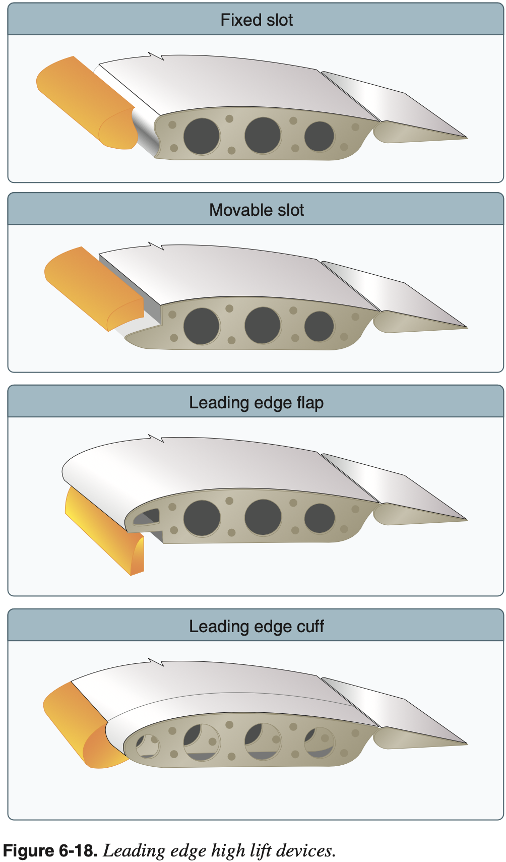
- Slots / Slats
- Located on the leading edge
- Allows higher angles of attack by redirecting airflow from under the wing to the top delaying separation
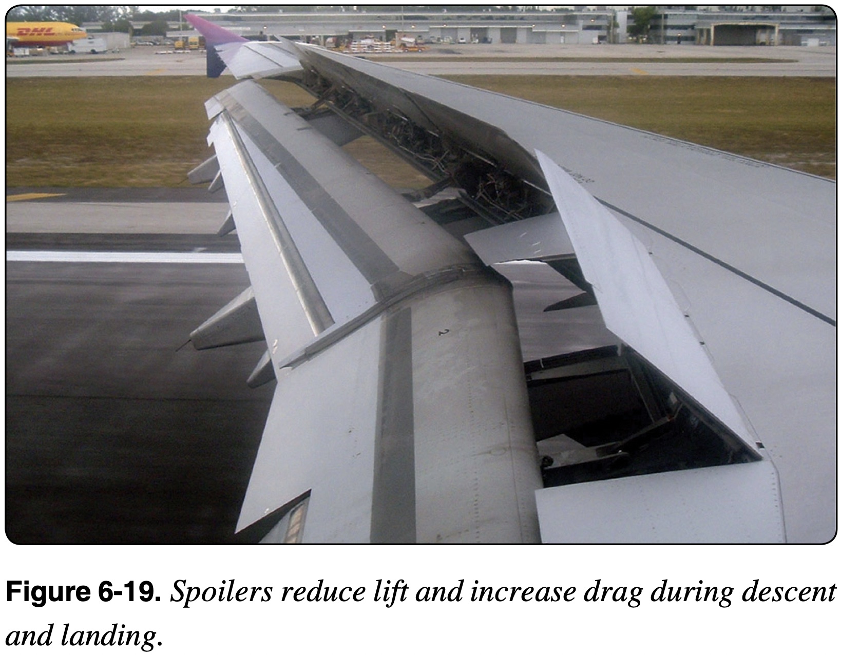
- Spoilers
- Reduce lift and increase drag
Flaps
NOTE
At the most fundamental level, flaps change the shape of the wing with the primary goal of changing the relationship between lift and drag.
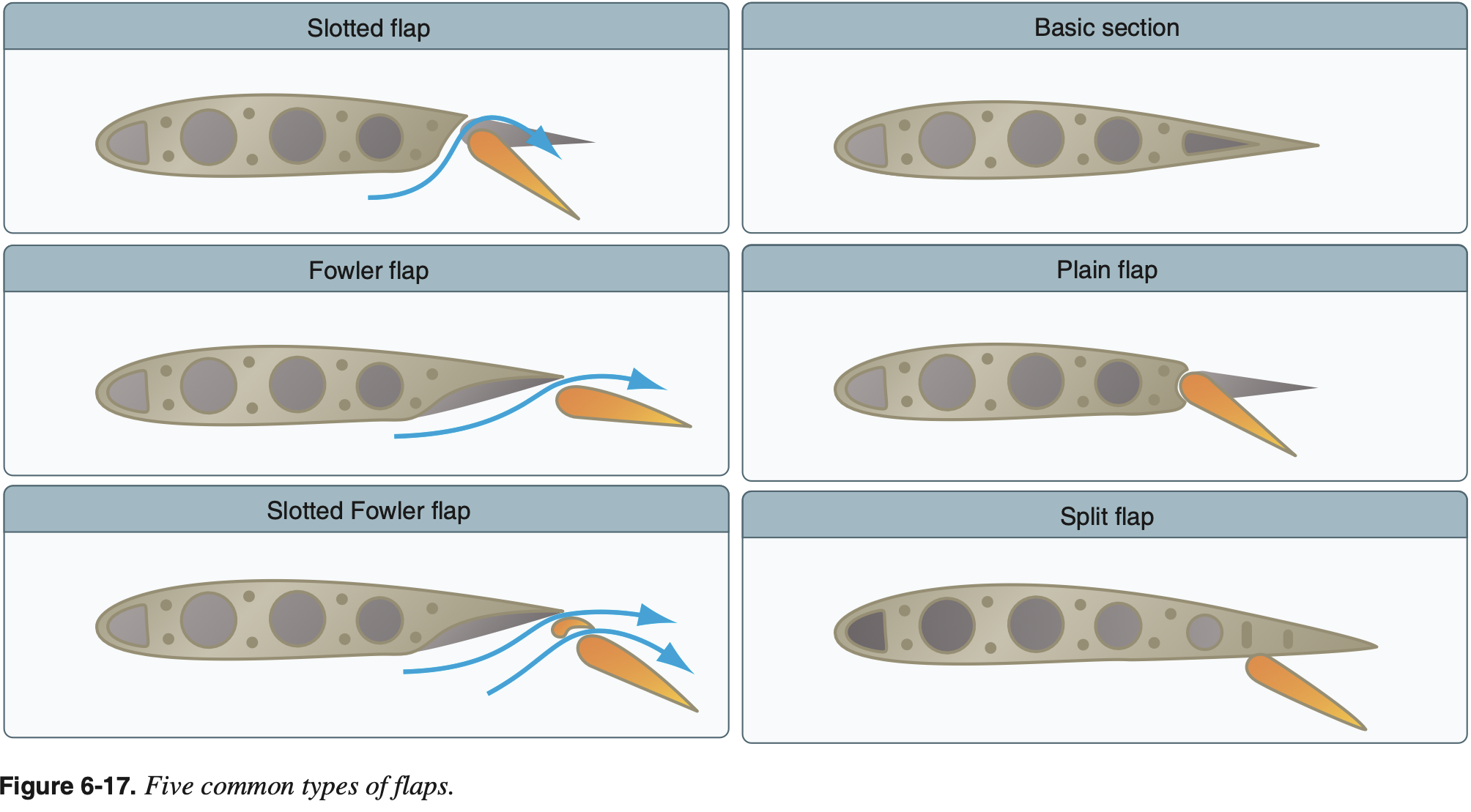
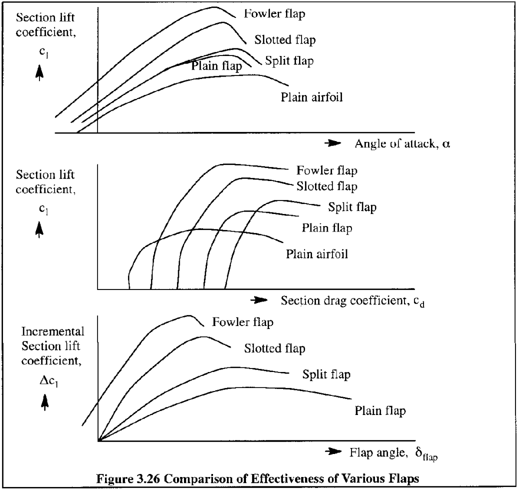
Flap Types
- Plain Flaps
- Characterized by a hinging a rearward section of an airfoil about a point within the airfoils contour
- Main effect is an increase effective camber of the airfoil
- Increases lift coefficient at zero angle of attack and reduces stall angle of attack
- Split Flaps
- Characterized by hinging only the lower portion of a rearward section of an airfoil
- Similar aerodynamically to plain flaps but with better high angle of attack performance due to less separation on the upper surface
- Creates least change in pitching moment
- Slotted Flaps
- Characterized by slots between the flap and main airfoil section when the flap is deflected
- Flap rotates about a point outside of the airfoils contour creating a gap, or a slot, through which air can flow
- Uses high energy air beneath the airfoil to delay separation over the flap
- Fowler Flaps
- Charaterized by a rearward translation of the flap resulting in an increase in the effective wing chord and correspondingly an increase in wing area
- Produces greatest change in pitching moment
- Greatest increase in lift with minimal changes in drag
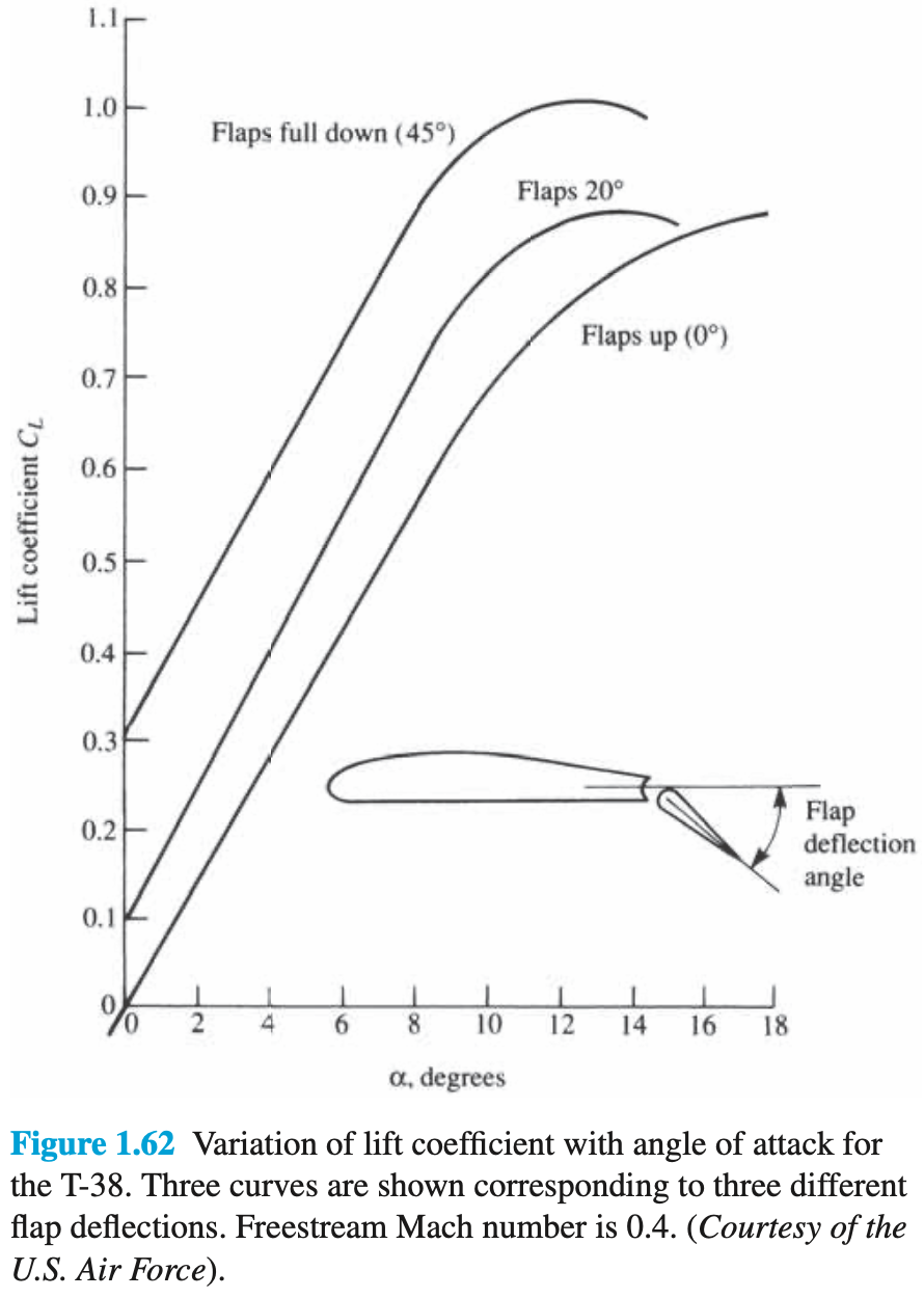
Flap Aerodynamics
For example, permit a higher
for a given thus permitting slower flight for takeoff and landing. Alternatively flaps my permit a larger
for a given , enabling the aircraft to better slow down. Basically - flaps shift the drag bucket to obtain the desired
at a given . The relationship between lift and drag is often plotted on a drag curve which is a generic term to describe a plot of drag (or the drag coefficient) versus a number of other variables.
One of these variables is lift (or the lift coefficient) in what is called a drag polar or drag bucket.
From Modeling and Simulation of Aerospace Vehicle Dynamics, Third Edition:
We go back to the latter part of the 19th century and find Otto Lilienthal experimenting with hang gliders. He took his hobby very seriously and is credited with relating lift and drag by what he called "die Flugpolare" (the drag polar).
Flaps change the camber of the wing's airfoil and thus the zero-lift angle of attack
Flaps also move the center of pressure (CP) aft on the airfoil
- This effect results in a nose-down pitching moment
- Other effects are change in airflow over horizontal stabilizer (e.g. more downwash contributing nose-up pitching moment), and increase in drag above the CG which may have different effects depending on the airplane.
- Such secondary effects are typically not as obvious
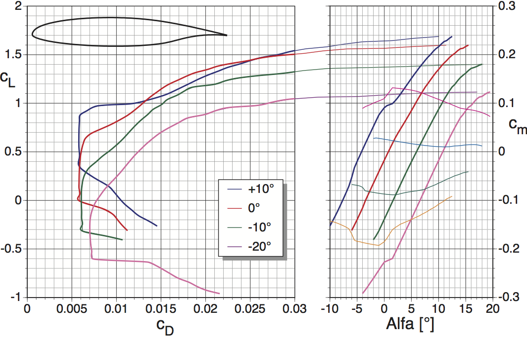
In the following picture, can see how the drag bucket changes for the given airfoil with different flap settings. For example, if takeoff
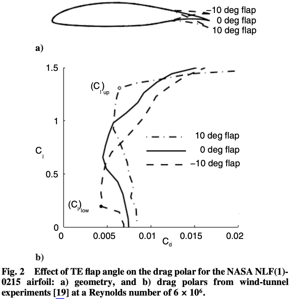
In the following picture, can see how the drag bucket changes for the given airfoil with different flap settings.
Flap Definitions
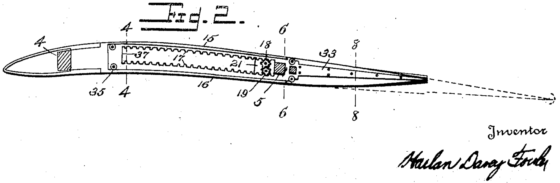
- The original 1921 patent by Harlan Davey Fowler was for a flap which would "maintain the general curvature and upper camber of the airfoil"
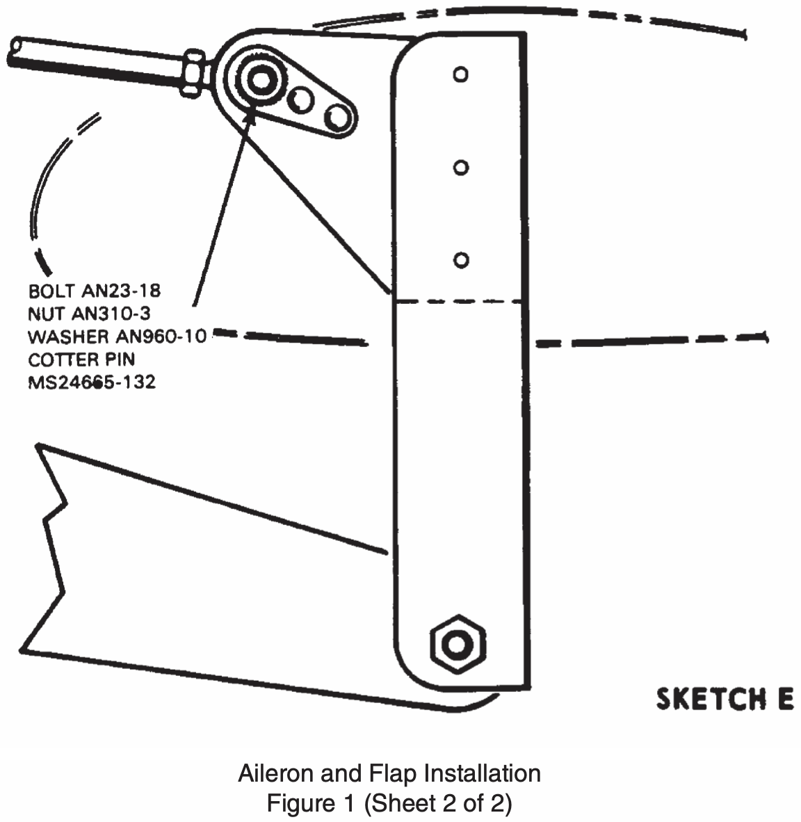
- Both the definitions by Roskam, "Plain trailing edge flaps are formed by hinging the rear-most part of a wing section about a point within the contour" and Sadraey, "hinged at the wing trailing edge" imply that the point about which a plain flap pivots must be within the cross section of the airfoil.
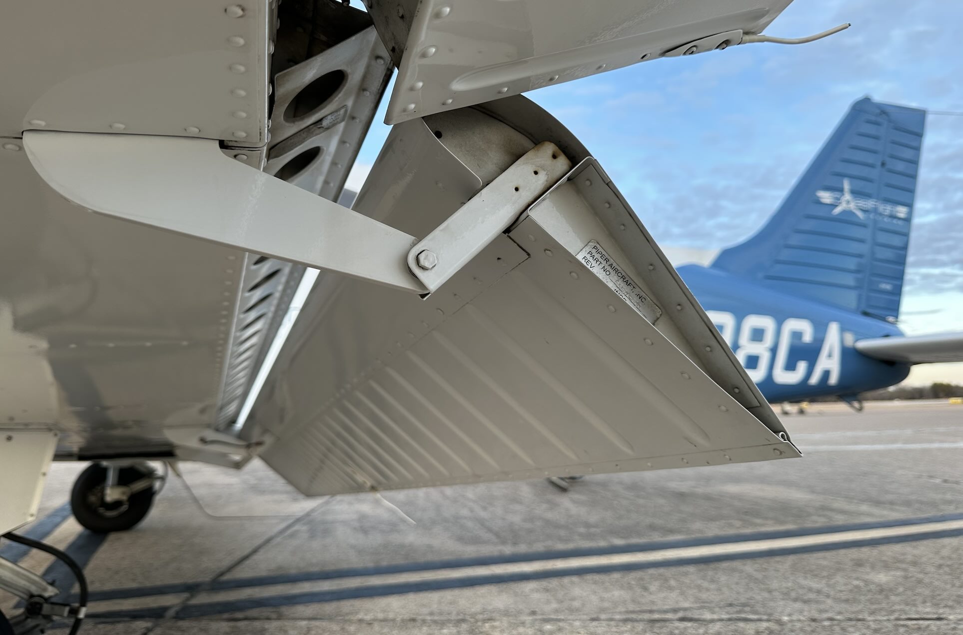
- Flaps such as those found on the Piper Archer or Cirrus SR22 whose pivot point is well outside of and below the airfoil cross section are therefore slotted flaps.
For more on flap definitions see
NASA The Wind and Beyond Volume II: Reinventing the Airplane
Key feature of the Fowler flap is a rearward translation of the flap resulting in an increase in the effective wing chord and correspondingly an increase in wing area
Mohammad H. Sadraey - Aircraft design : a systems engineering approach:
A Fowler flap has a special mechanism such that when deployed, it not only deflects downward but also translates or tracks to the trailing edge of the wing. The second feature increases the exposed wing area...
Jan Roskam - Airplane Aerodynamics and Performance:
The Fowler flap (see Figure 3.22d) employs the same principle as the slotted flap, but it also moves backward while deflecting downward. The backward motion increases the effective wing area.
Slots
- A leading-edge slot is a fixed (non-closing) gap behind the wing's leading edge.
Slats
- Like a slot, but can be retracted when not needed
- Located on the leading edge
- Delays airflow separation allowing higher angles of attack by redirecting airflow from under the wing to the top delaying separation
Spoilers
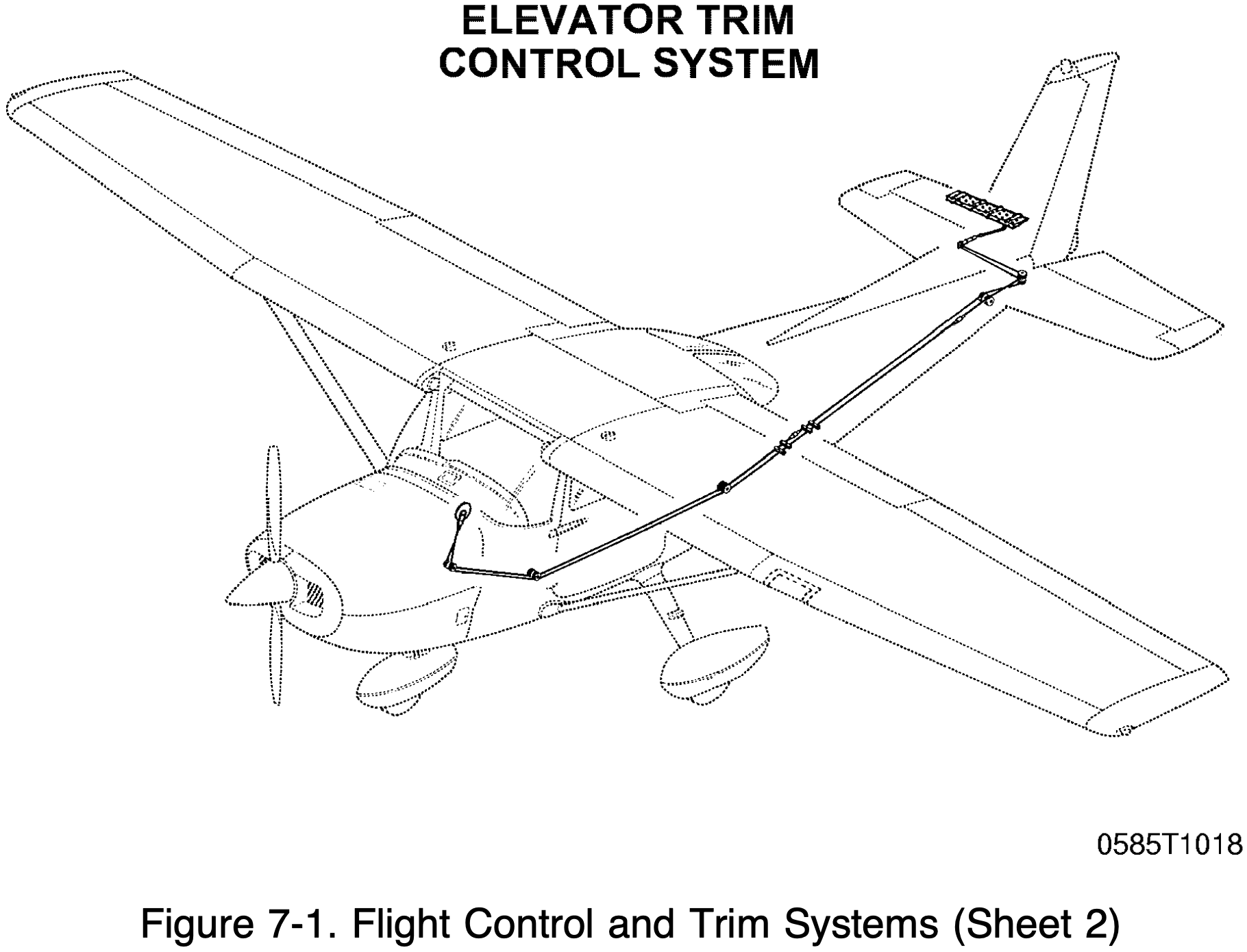
Trim Controls
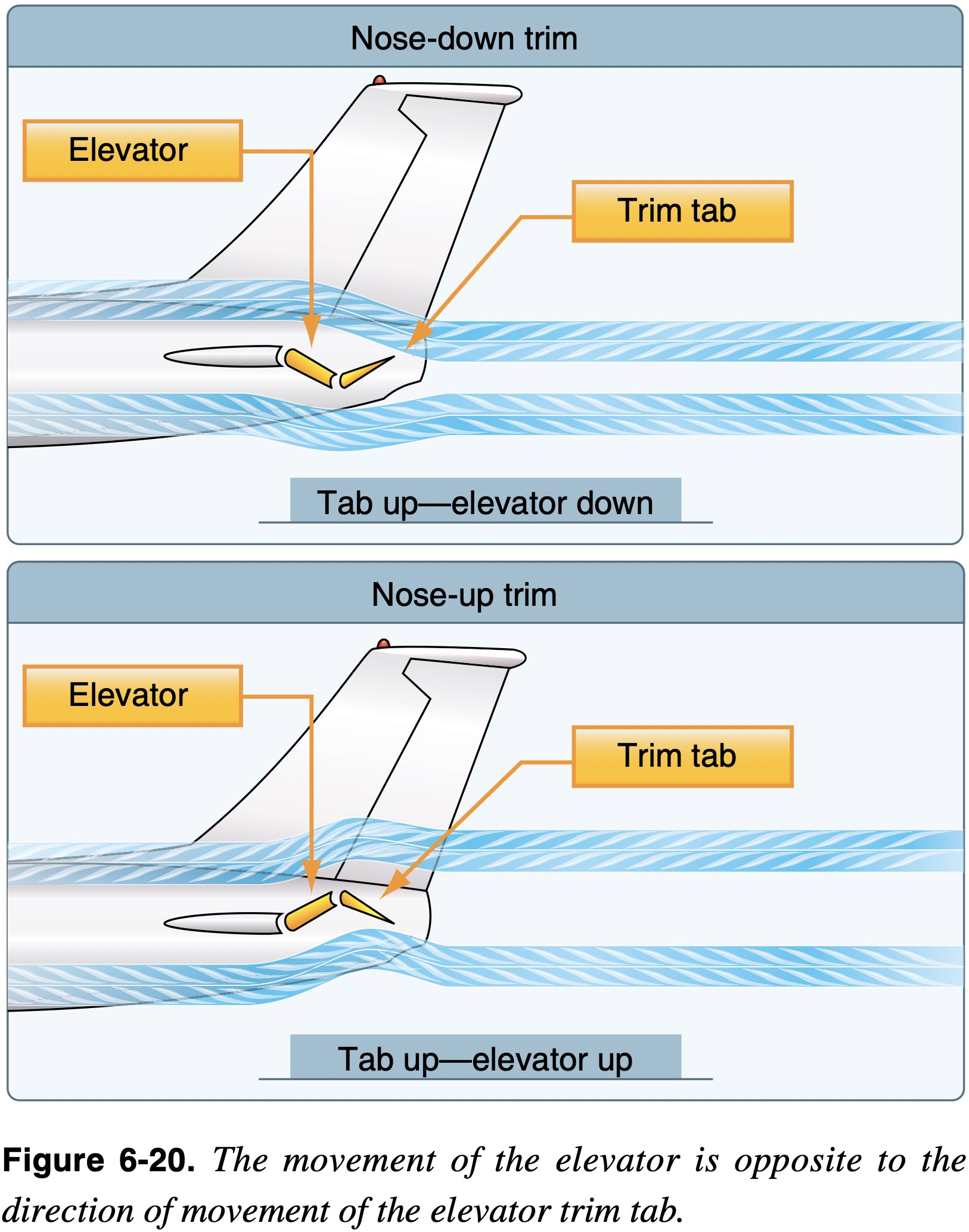
Trim Systems
Used to relieve the pilot of the need to maintain constant pressure on the flight controls.
- Trim systems usually consist of flight deck controls and small hinged devices attached to the trailing edge of one or more of the primary flight control surfaces.
- Some trim and related systems
- Trim tabs
- Balance tabs
- Like automatic trim tabs
- Antiservo tab
- Move in same direction as stabilator (opposite movement of balance tab)
- Designed to affect control feel
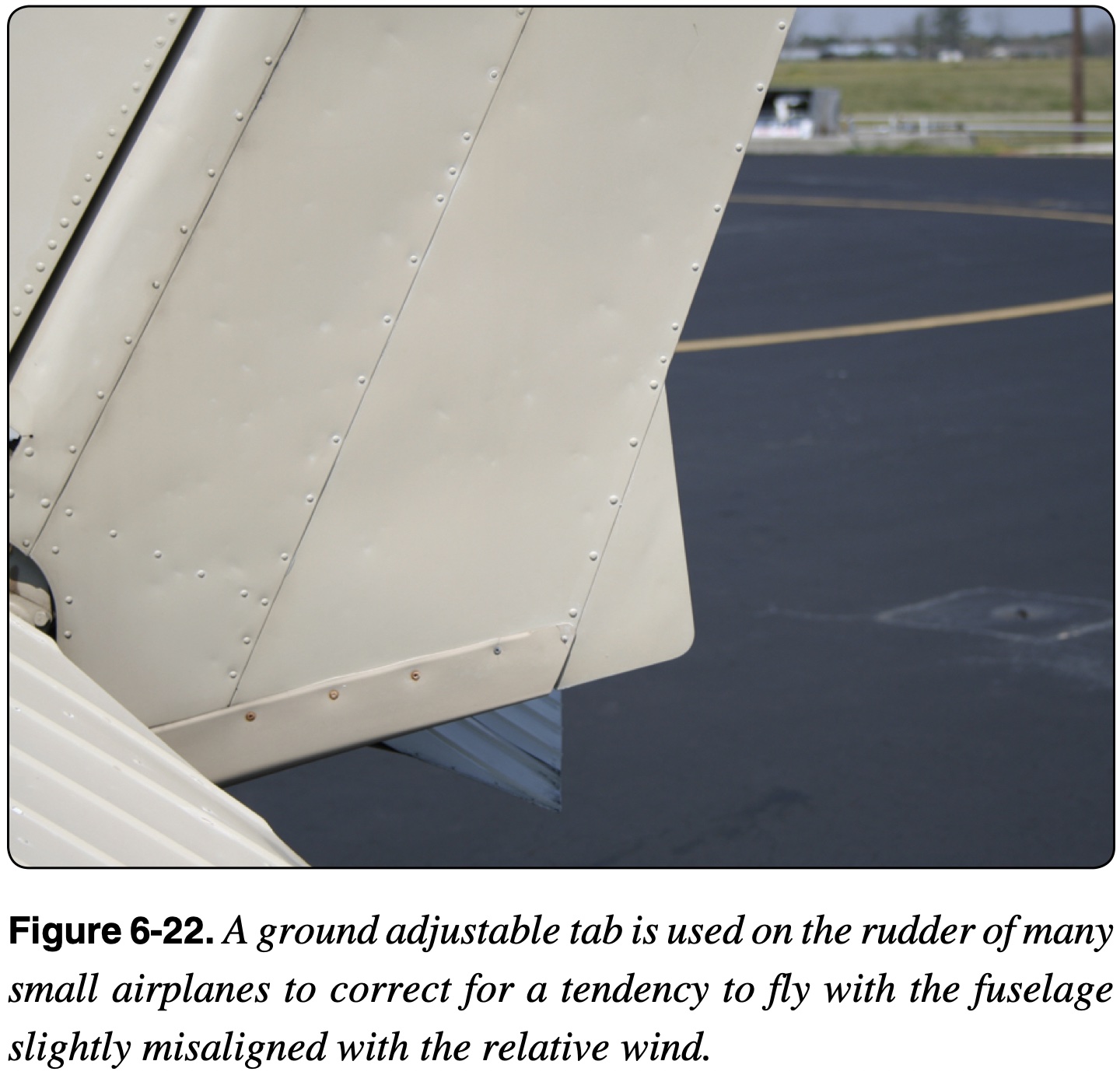
- Ground adjustable tab

VOR
Overview
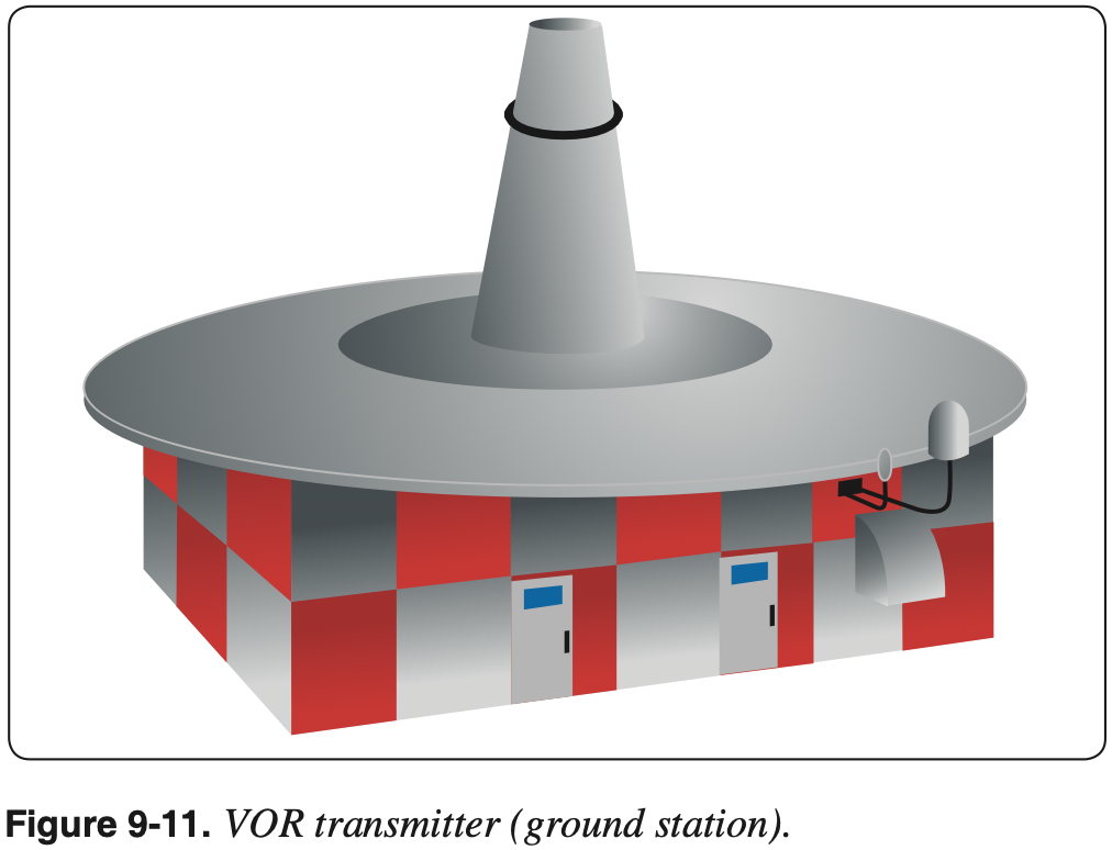
VOR
Very High Frequency (VHF) Omni-directional Range (VOR) is a type of radio based navigation system that allows aircraft to determine their position relative to a ground based antenna.
- AIM 1-1-3 VHF Omni-directional Range (VOR)
- VOR is a ground-based station which broadcasts signals that a plane can receive that indicates a radial that is the magnetic bearing to the station.
- VOR frequencies are standardized in the very high frequency (VHF) band between 108.00 and 117.95 MHz.
- The Omnibearing Selector (OBS) (also referred to as the course selector) is a dial that can be rotated to select a desired course.
- Inside the cockpit, the frequency corresponding to a particular VOR is input and the VOR indicator displays information about where the aircraft is relative to that VOR.
- Radials are projected outward from the station.
- However, any radial can be picked up regardless of where the aircraft is relative to the VOR.
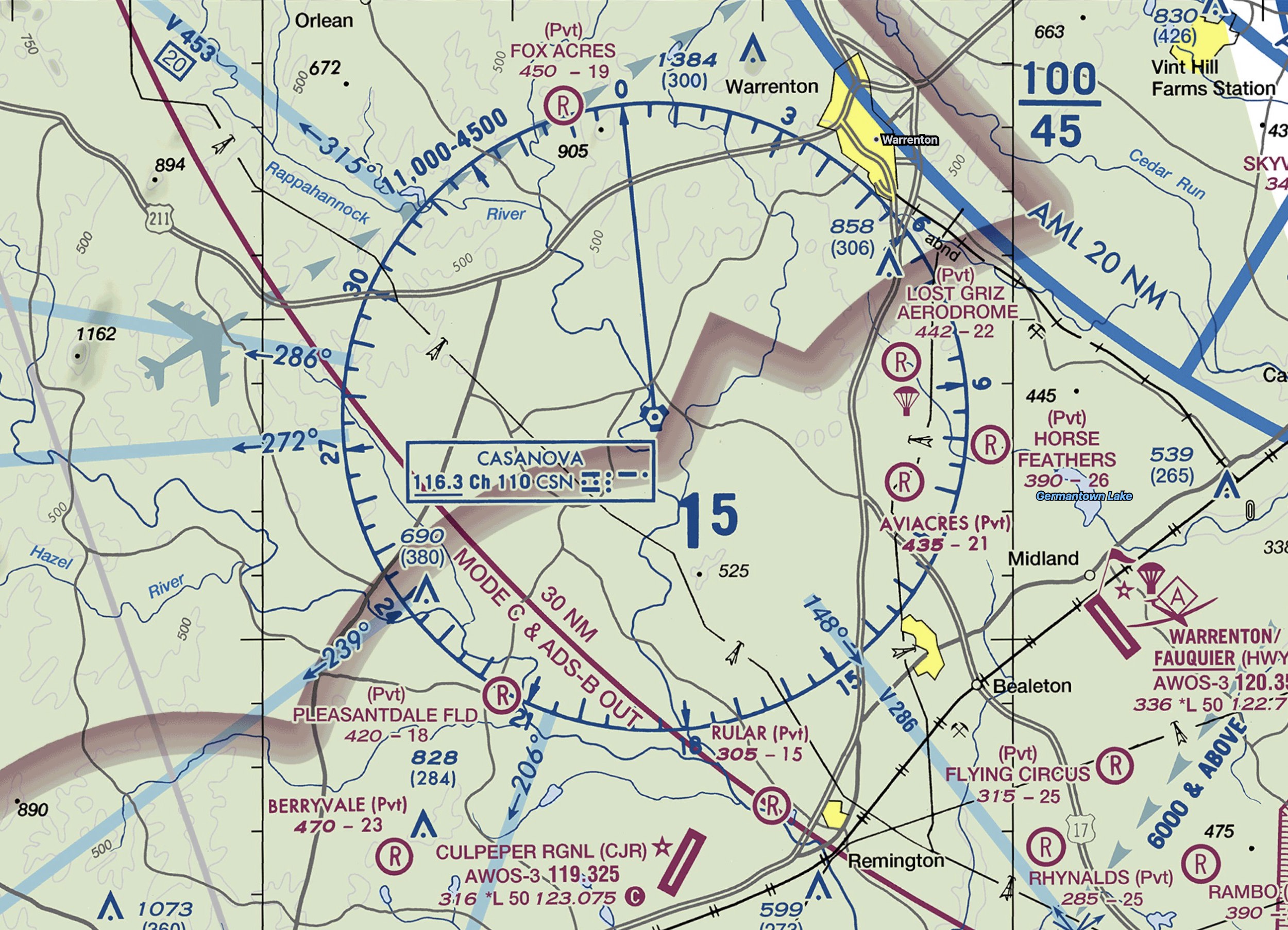
- For example, if we are south of the Casanova VOR, we can pick up the 360° radial that is projected northward from the station.
- The information provided by a VOR alone is independent of the heading of the aircraft.
- In addition to the radial information, we also get information as to whether the selected course will take us to or from the station.
- So in the example above about being south of Casanova VOR, if we dialed the 180° radial we would see a
FROMindication, but if we dialed in the 360° radial we would seeTO. - Remember this information is irrespective of the aircraft's heading.
- So in the example above about being south of Casanova VOR, if we dialed the 180° radial we would see a
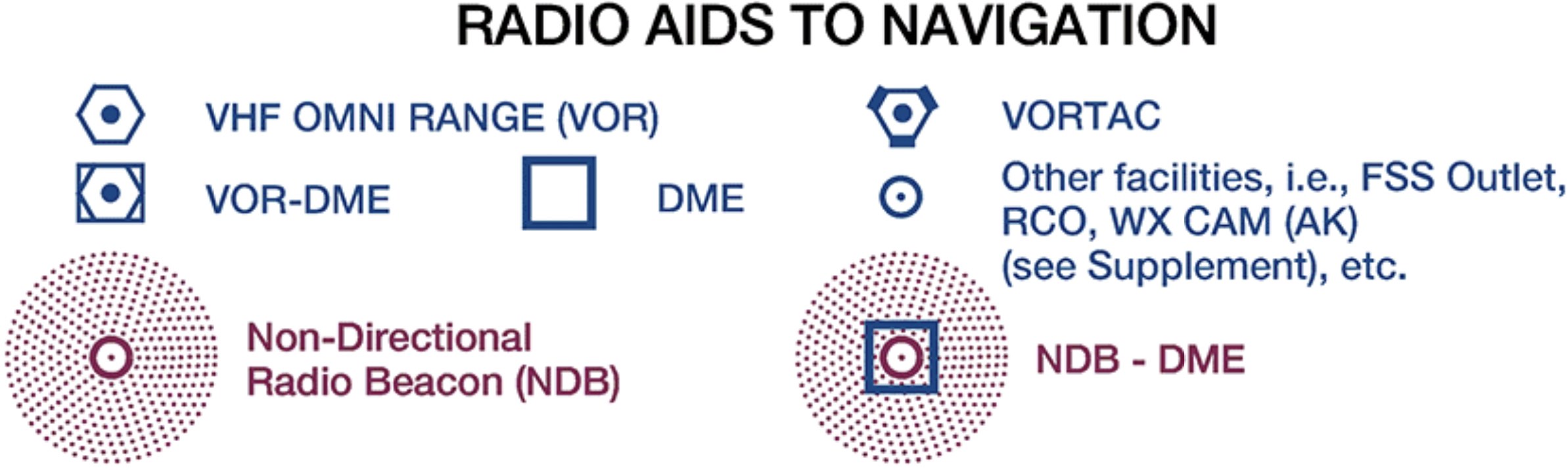
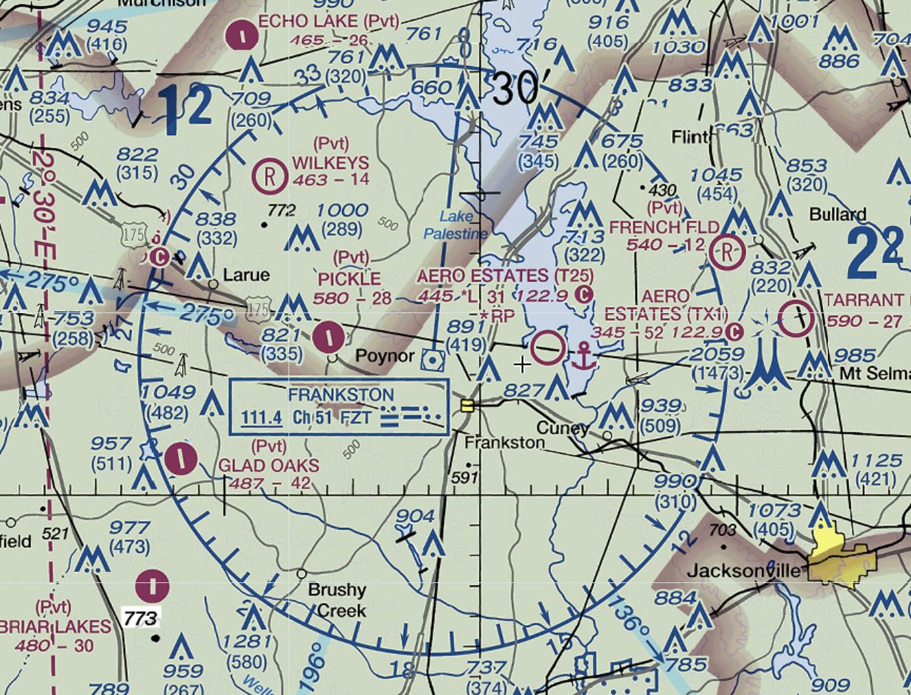
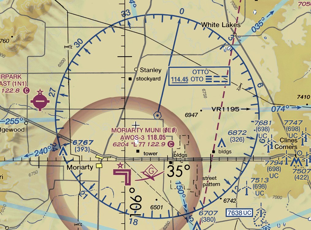
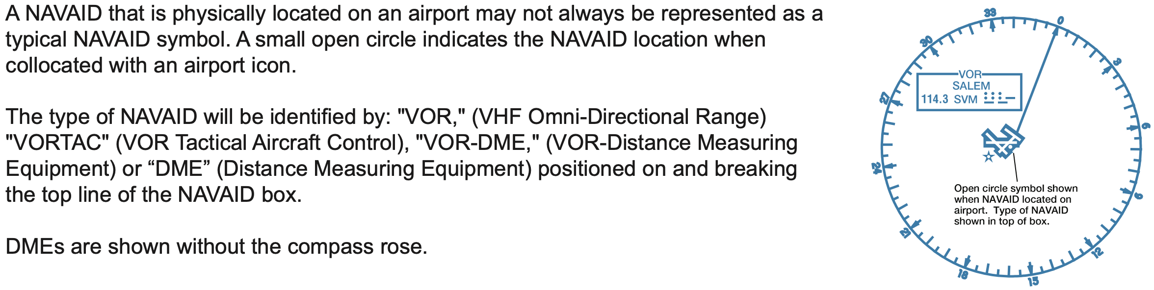
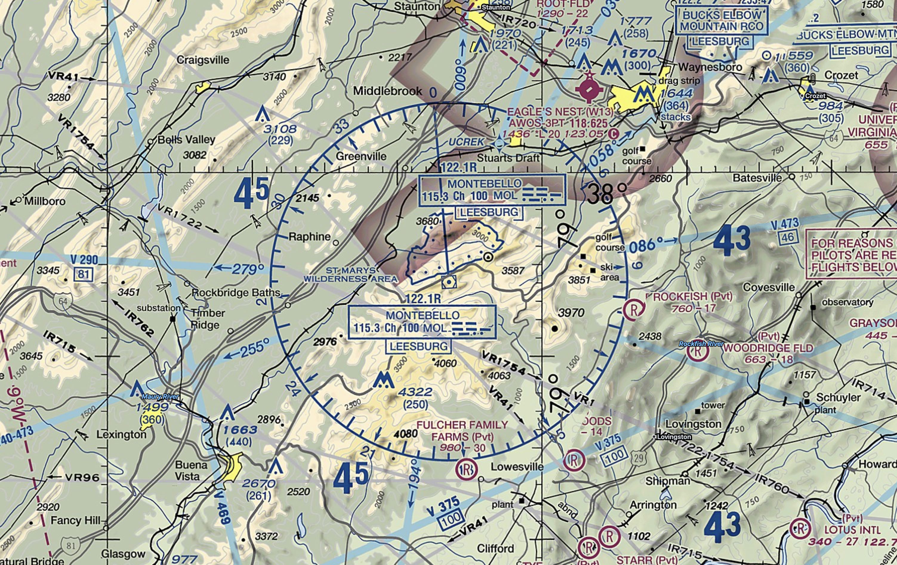
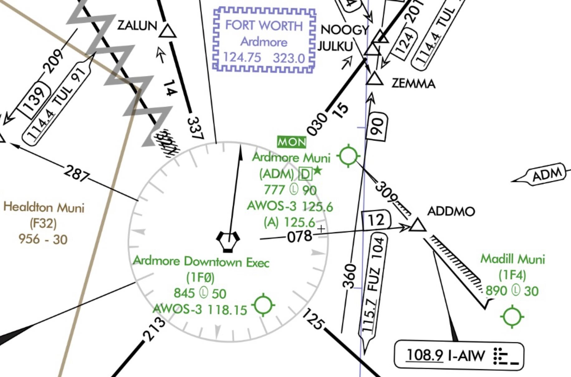
VOR Symbols on Charts
- There are several different types of VOR facilities, each of which slightly different capabilities.
- These facilities are described more in detail below.
- For now, note each different type of VOR facility is charted slightly differently on aeronautical charts.
- The screenshots below are from VFR sectionals, but the same symbols are used on IFR charts.
- The most common type of VOR facility is the VORTAC, then the VOR/DME, with VOR being fairly uncommon.

VOR Indicator
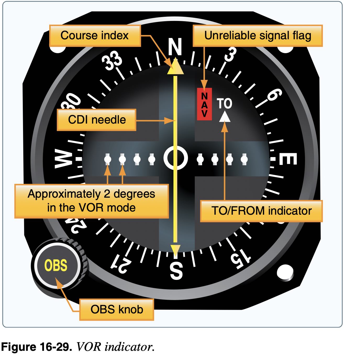
- The VOR indicator also provides information with the Course Deviation Indicator (CDI)
- This gives the pilot information as to how far off course they are when they have selected a radial by way of a needle that deflects left or right from center
- Full-scale deflection on VOR is a deviation of 10 to 12 degrees.
- Each 1 nm from the VOR, two adjacent radials are 100 ft further apart
- So 60 nm from the VOR two adjacent radials would be 6000 ft apart or about 1 nm
- Or if 30 nm from station and 2 degree deflection on needle, are 6000 ft off course, or about 1 nm off course.
- Make sure the selected VOR is correct and functional before using
- Check the morse code audio
- Ensure the avionics displays the VOR identifier
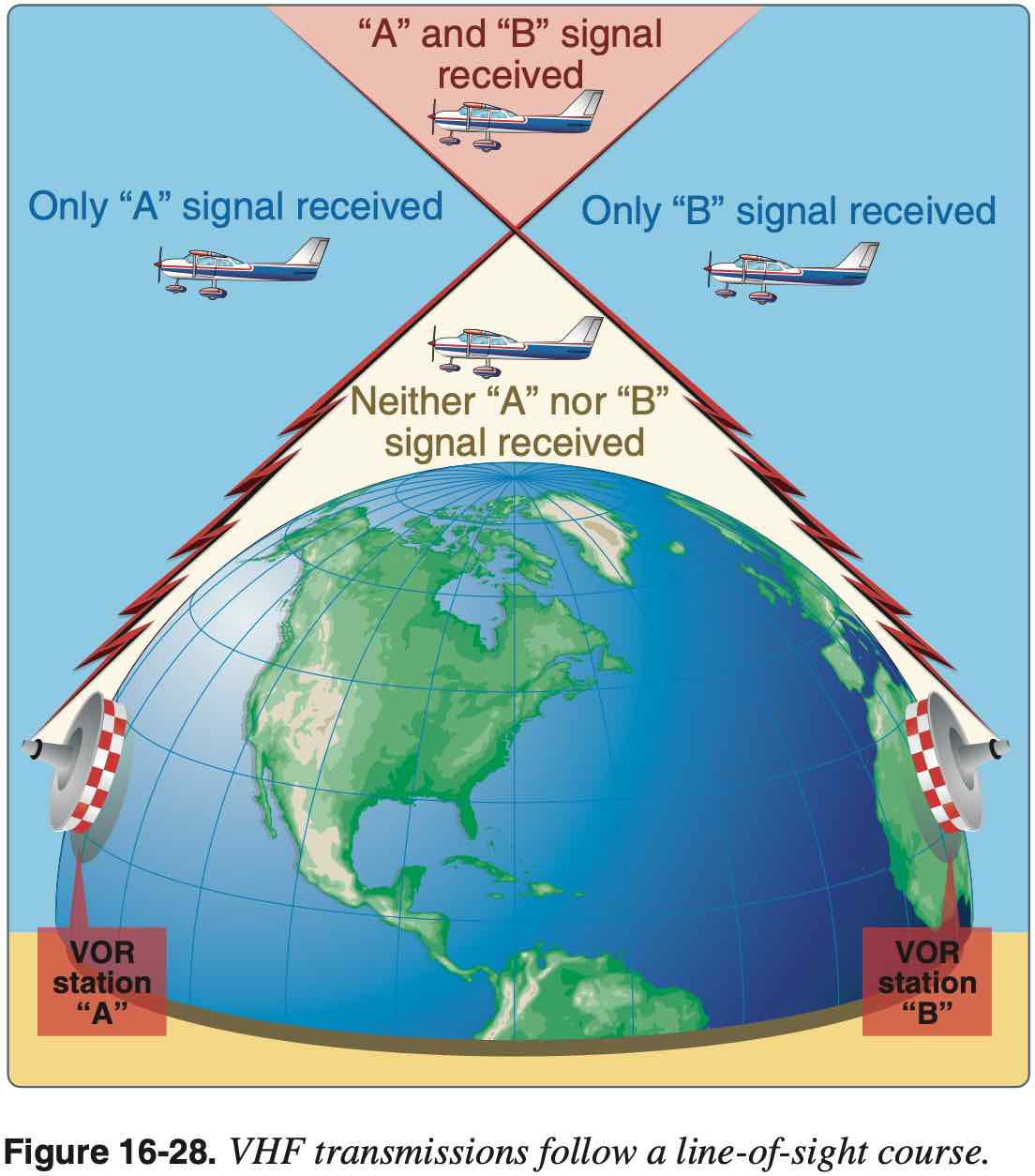
- VOR is line-of-sight transmission
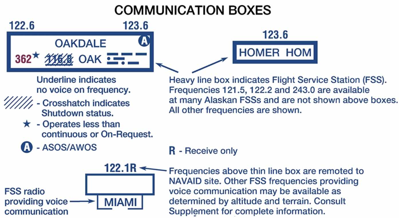
Voice Capabilities
- VORW is a VOR without voice
- VORW are denoted on charts by underlining the VOR frequency
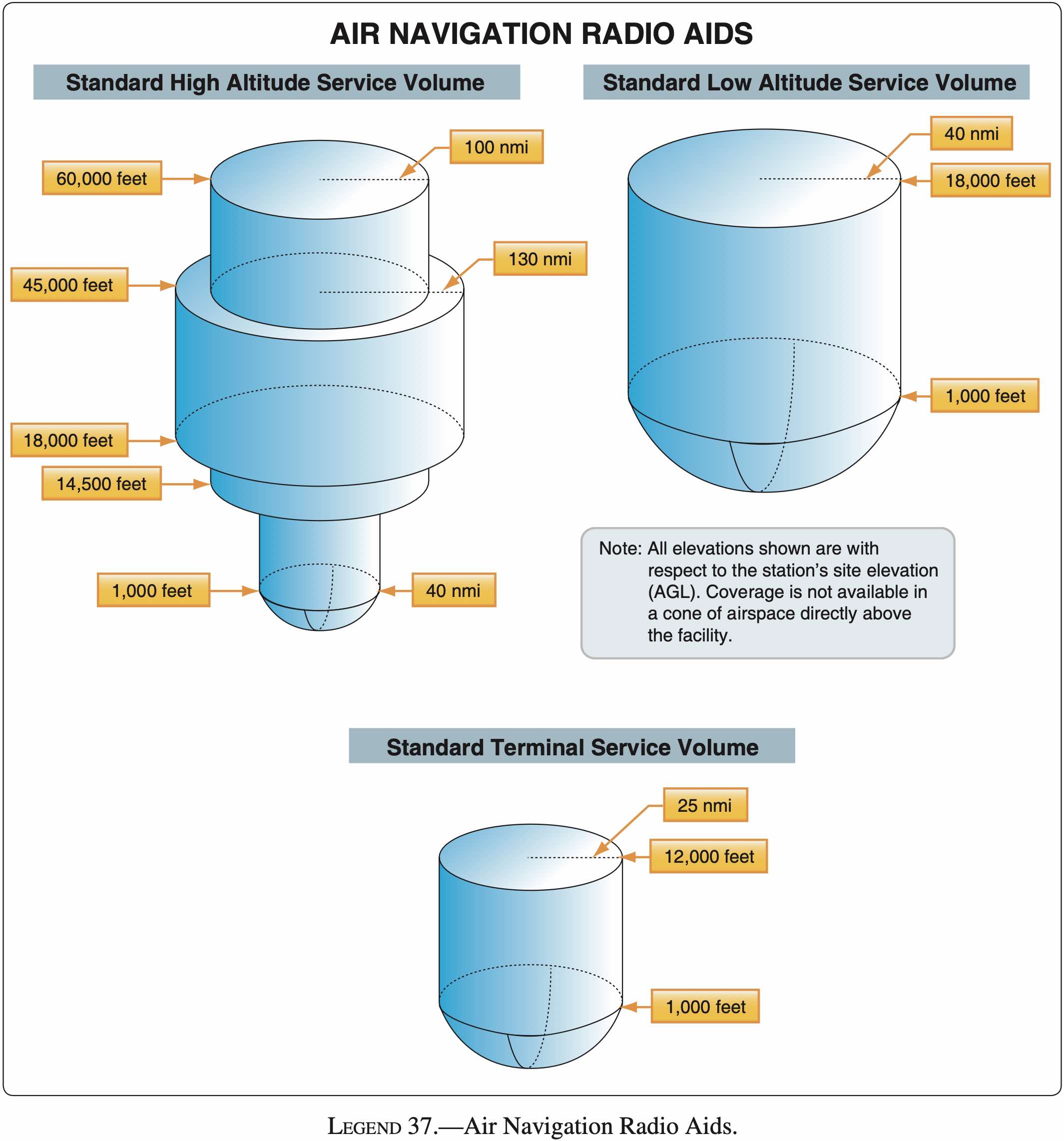
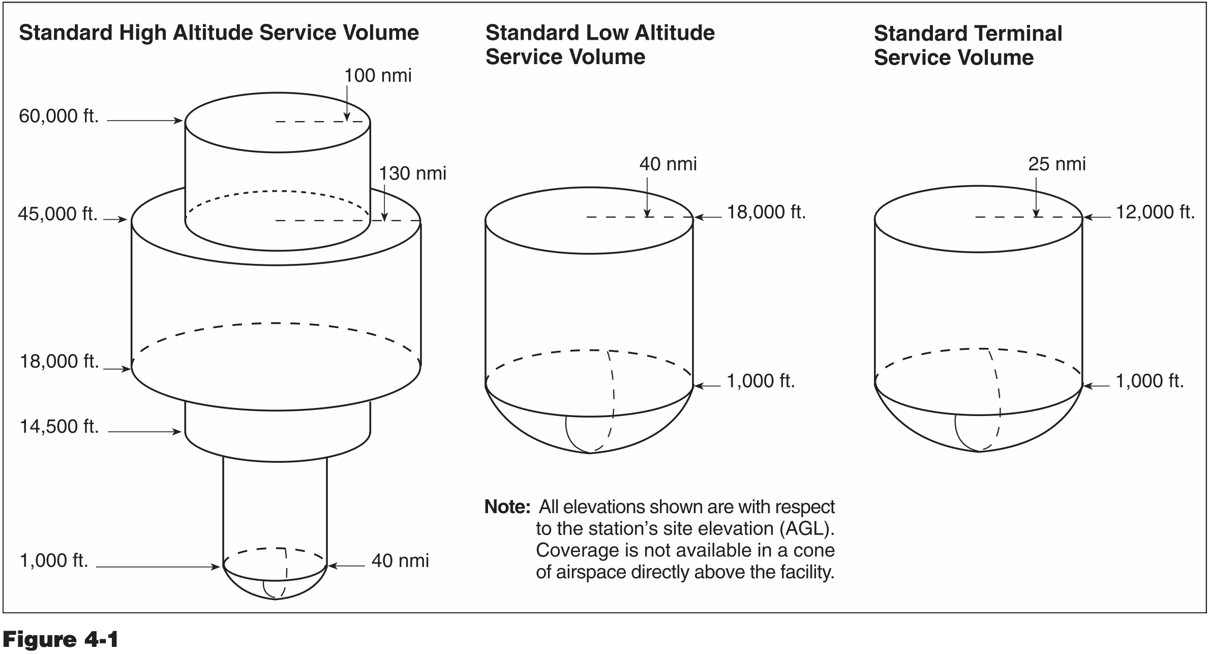
Legacy Service Volumes
- Three classes of legacy VOR / VORTAC that define service volume:
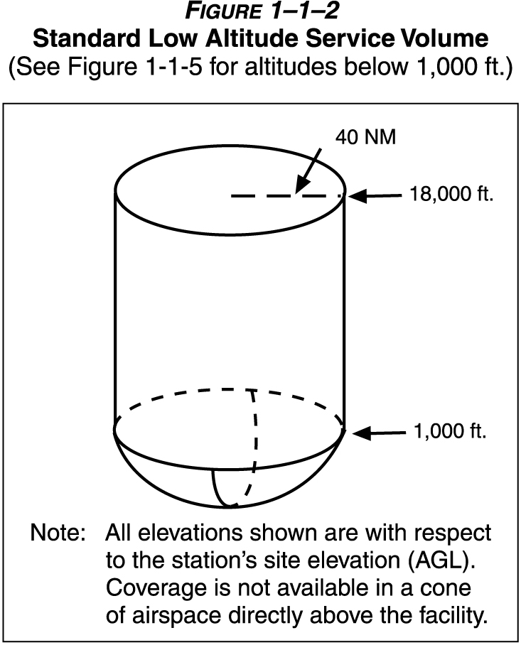
- T (Terminal)
- L (Low altitude)
- H (High altitude)
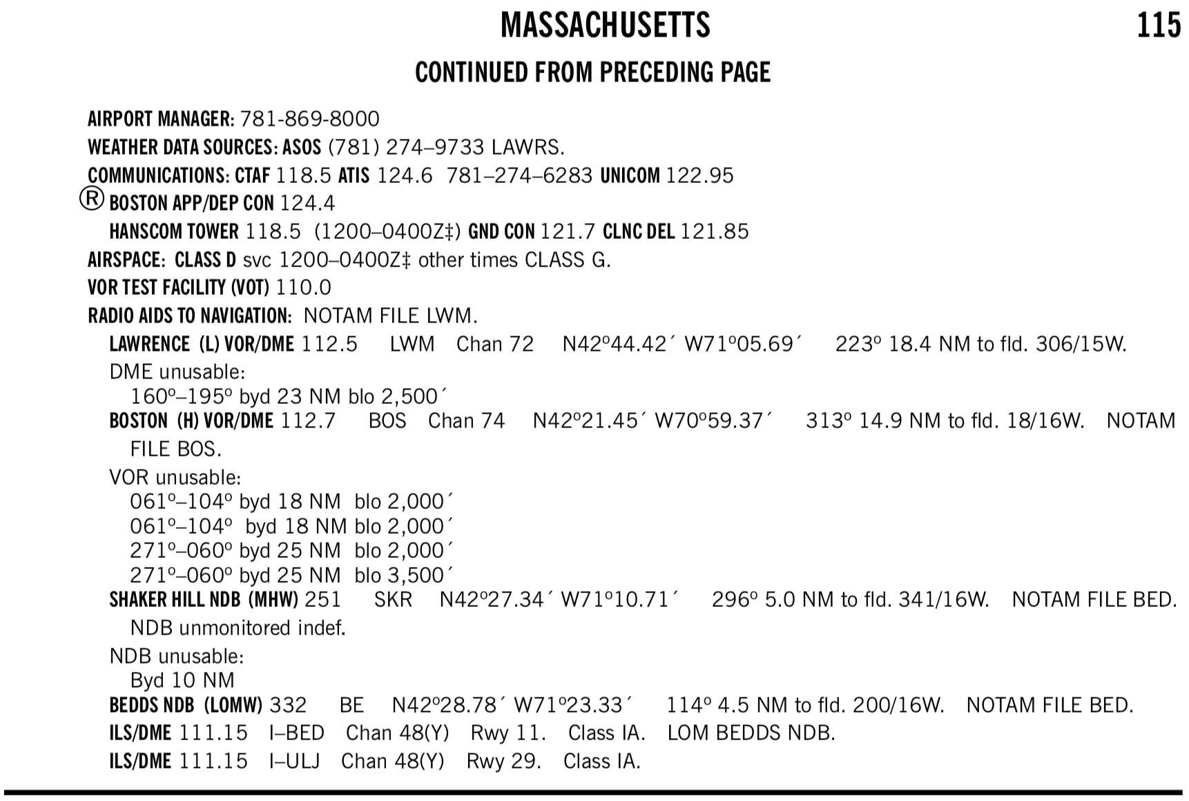
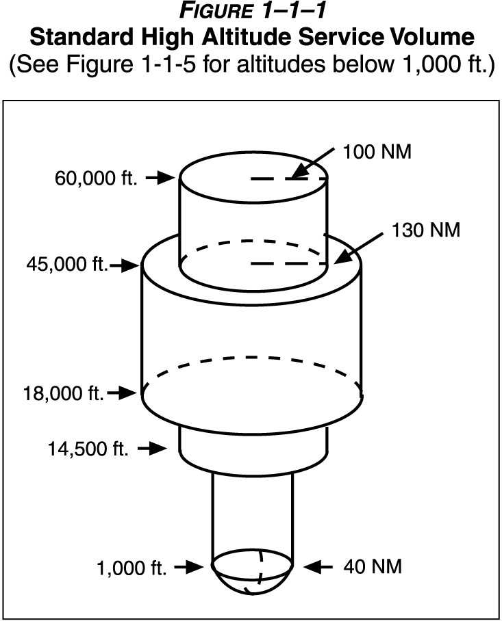
1-1-8. NAVAID SERVICE VOLUMES
a. Most air navigation radio aids which provide positive course guidance have a designated standard service volume (SSV).
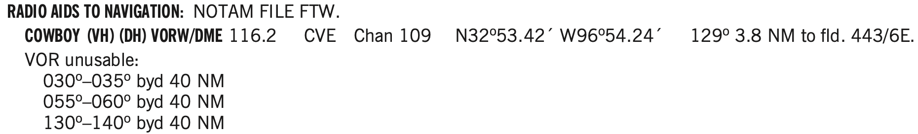
- To find the service volume class of a given VOR
- Can find the service volume in the Chart Supplement.
- For example see
BOSTON (H) VOR/DMEindicating it is a high class(H)
- For example see
- See also: Aviation StackExchange How do you know if a VOR is High, Low, or Terminal?
- Can also check low and high altitude IFR charts to see which appear on each.
- Here it is implicit, but Low Class
(L)VORs will not appear on the IFR High Chart as their service volume tops out at 18,000 ft. AGL, and IFR charts are for use at or above 18,000 ft. MSL. - Note the difference between AGL and MSL. I don't know at what altitude the IFR high charts top out at, but there are Maximum Authorized Altitudes (MAA) so conceivably a Low Class
(L)VOR located at 10,000 ft. MSL, for example, would provide 40 nm radius of service up to 28,000 ft. MSL and be used on a high chart. - In any case, following what is on the IFR charts for VOR navigation ensures a pilot need not worry too much about the various service volumes.
- Here it is implicit, but Low Class
- Can find the service volume in the Chart Supplement.
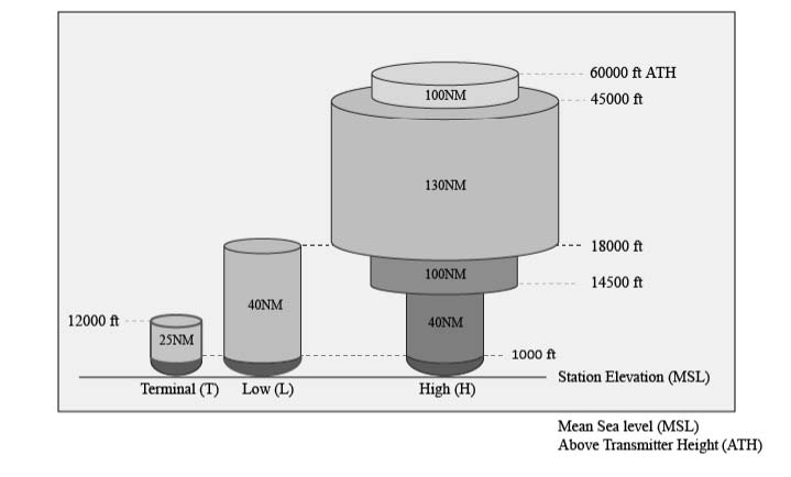
New Service Volumes
- Insert picture here
TACAN, VORTAC, and VOR/DME
- VOR is present in three different navigational aids
- VOR
- This is the fundamental capability described above
- VOR/DME
- When distance measuring equipment (DME) is installed with the VOR, tuning the VOR VHF frequency automatically selects the corresponding UHF DME frequency
- DME is affected by slant-range errors, worse when closer to station and higher altitudes
- AIM 1-1-7 Distance Measuring Equipment (DME)
- VORTAC
- Combination of VOR and TACAN, where TACAN is military equipment, but provides DME to civilian users
- Provides three pieces of information
- VHF azimuth information
- UHF TACAN azimuth information (like azimuth provided by VOR but for military only)
- UHF TACAN distance information (can be used by non-military)
- If VORTAC undergoing maintenance will not hear the morse code identifier
- DME and VOR morse codes are transmitted seperately (even though they are the same identifier)
- DME identifier is transmitted once for each 3-4 times the VOR identifier is transmitted
- So depending on what is heard when listening for the identifier you can tell whether the DME is out or the VOR or both
- DME is affected by slant-range errors, worse when closer to station
- TACAN technology is very different from civilian DME, but the pilot's interaction with each is the same
- AIM 1-1-5 Tactical Air Navigation (TACAN)
- AIM 1-1-6 VHF Omni-directional Range/Tactical Air Navigation (VORTAC)
- VOR
- VHF radio band is 30 to 300 MHz
VOR MON
As VORs are gradually being phased out in favor of GPS, a limited network of VORs will be kept which will make up the VOR MON network, and enable some level of navigation using this system in the event that GPS is unavailable.
Certain airports are also designated MON airports.
According to the Aeronautical Chart User Guide Complete:
MON Airports with the Airport designator at the top of the Airport Data Block. The MON designation is to alert pilots to those airports that have retained ILS and VOR instrument approach procedures for safe recovery in the event of a GPS outage. Refer to the Aeronautical Information Manual (AIM) for expanded MON Airport guidance.
VOR Check
- Recall from AVIATE acronym, VOR needs to be checked every 30 days for IFR
- VOR accuracy requirements 14 CFR §91.171(b), (c)
- VOT: +/- 4 deg
- Can be checked on the ground or in the air, as indicated in the chart supplement for that facility
- Ground checkpoint: +/- 4 deg
- Airborne checkpoint: +/- 6 deg
- Dual check: within 4 deg
- VOT: +/- 4 deg
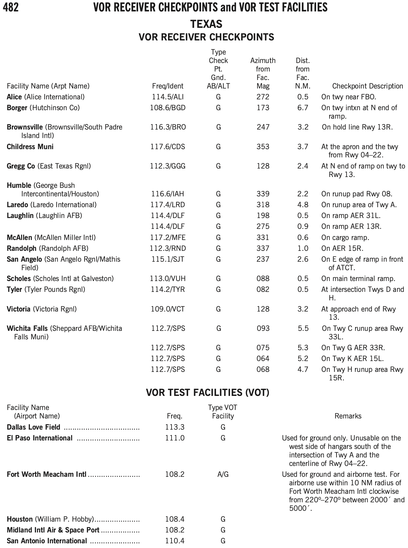
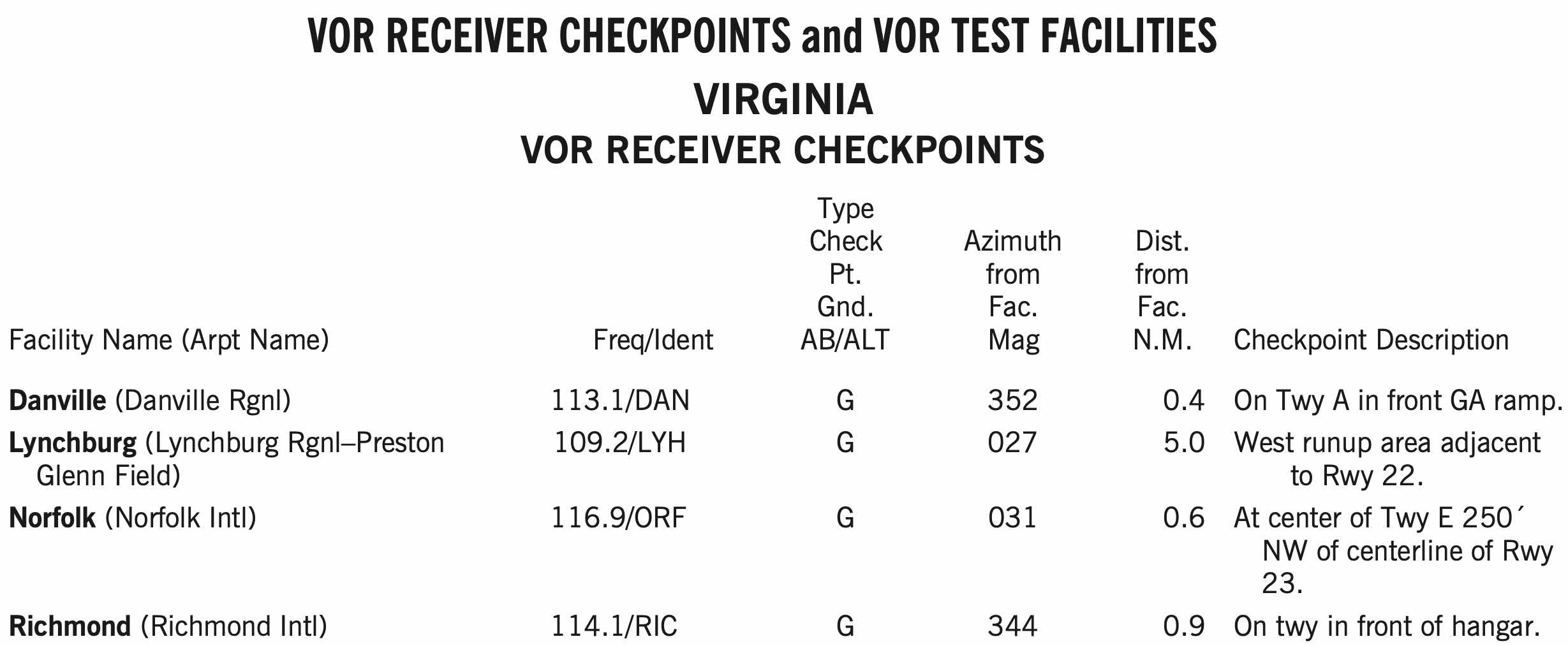
- Can find VOT facilities and VOR checkpoints in the chart supplement.
- Log the results of the VOR accuracy test in the aircraft logbook or other record including the PADS acronym:
- P - Place
- A - Accuracy (bearing error)
- D - Date
- S - Signature
- VOT is the most convenient way to perform a VOR check if your home airport happens to have one
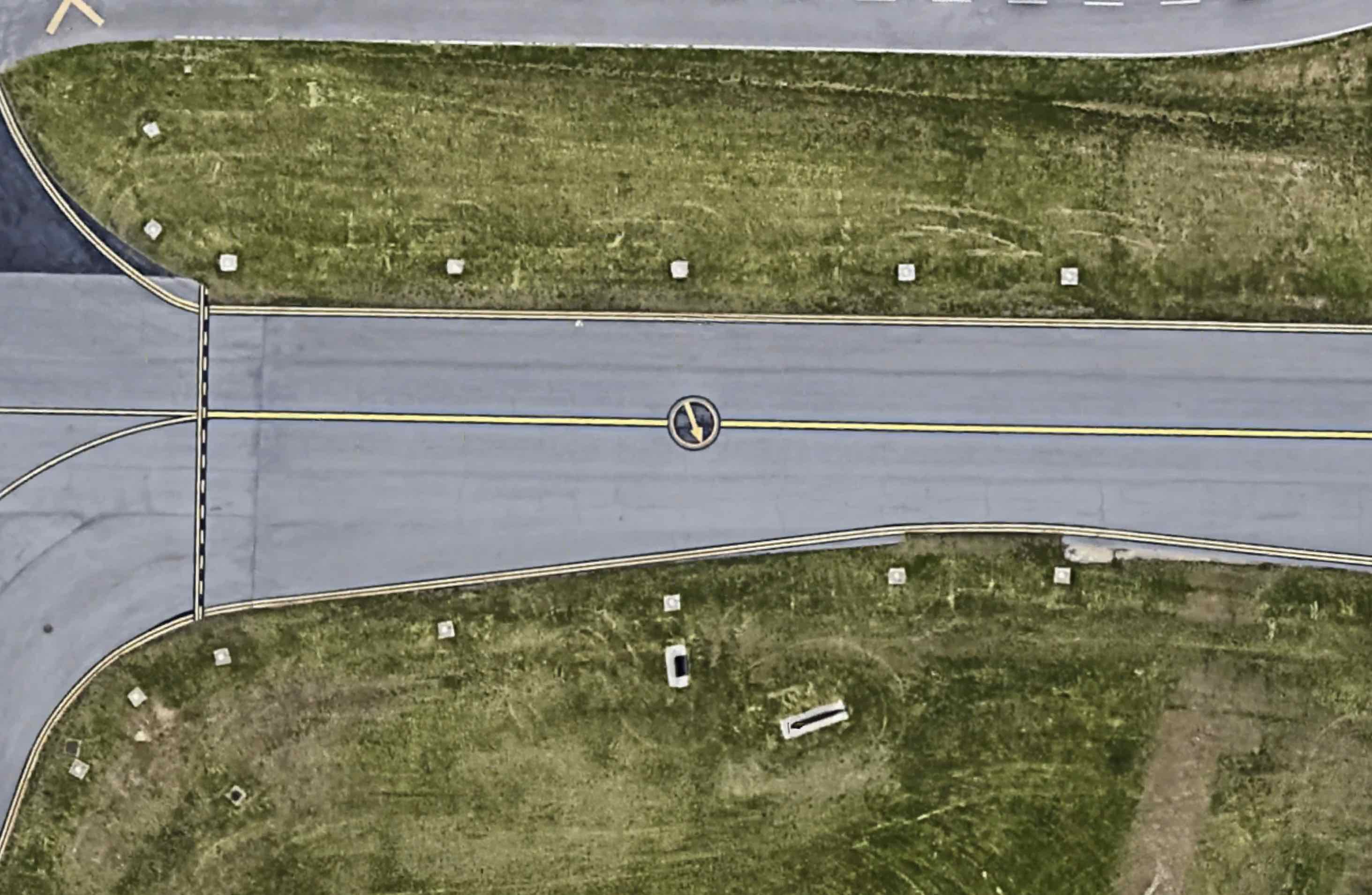
- Similarly, ground checkpoints are also a convenient option
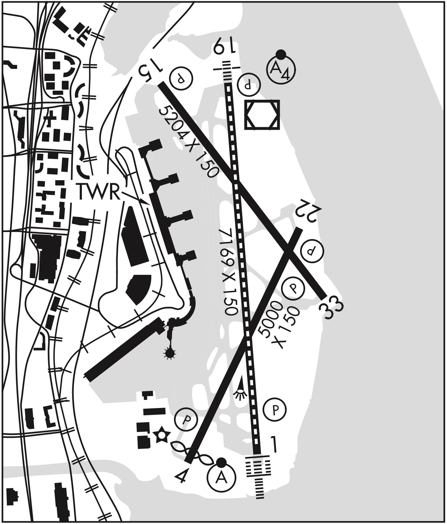
VOR Ground Checkpoint
- Has a sign in front of the arrow with the radial and frequency
VOT Check
- A VOT is a facility located at certain airports that emits a signal that can be used to test a plane's VOR receiver
- The VOT signals are generally designed to be used while on the ground, but some are designated as usable in air, with certain restrictions
- This information can be found in the chart supplement
- Dial a course of 180° in using the OBS, should see the needle center (within +/- 4 degrees) with a
TOindication.