Aircraft Flight Instruments
This page covers the portion of Task B. Aircraft Flight Instruments and Navigation Equipment from the FAA-S-ACS-8C Instrument Rating Airplane Airman Certification Standards pertaining to aircraft flight instruments.
Objective
To determine the applicant exhibits satisfactory knowledge, risk management, and skills associated with managing instruments appropriate for an IFR flight.
Pitot-Static System
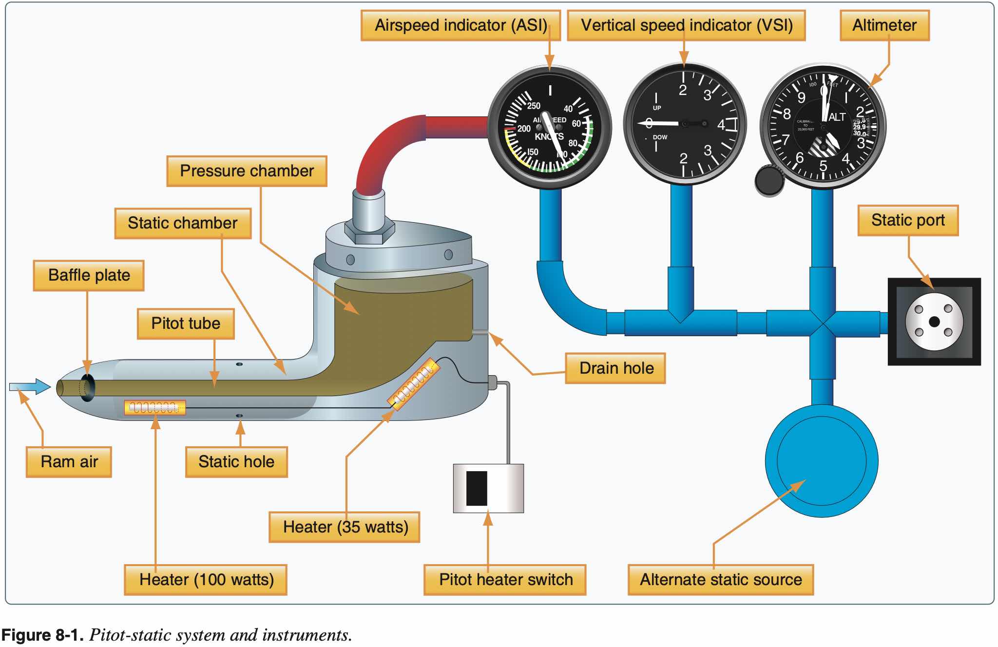
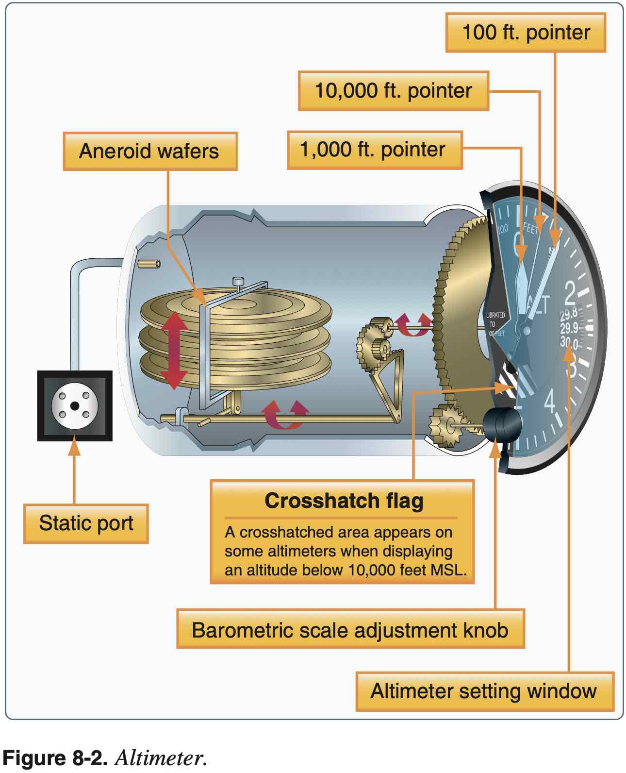
Altimeter
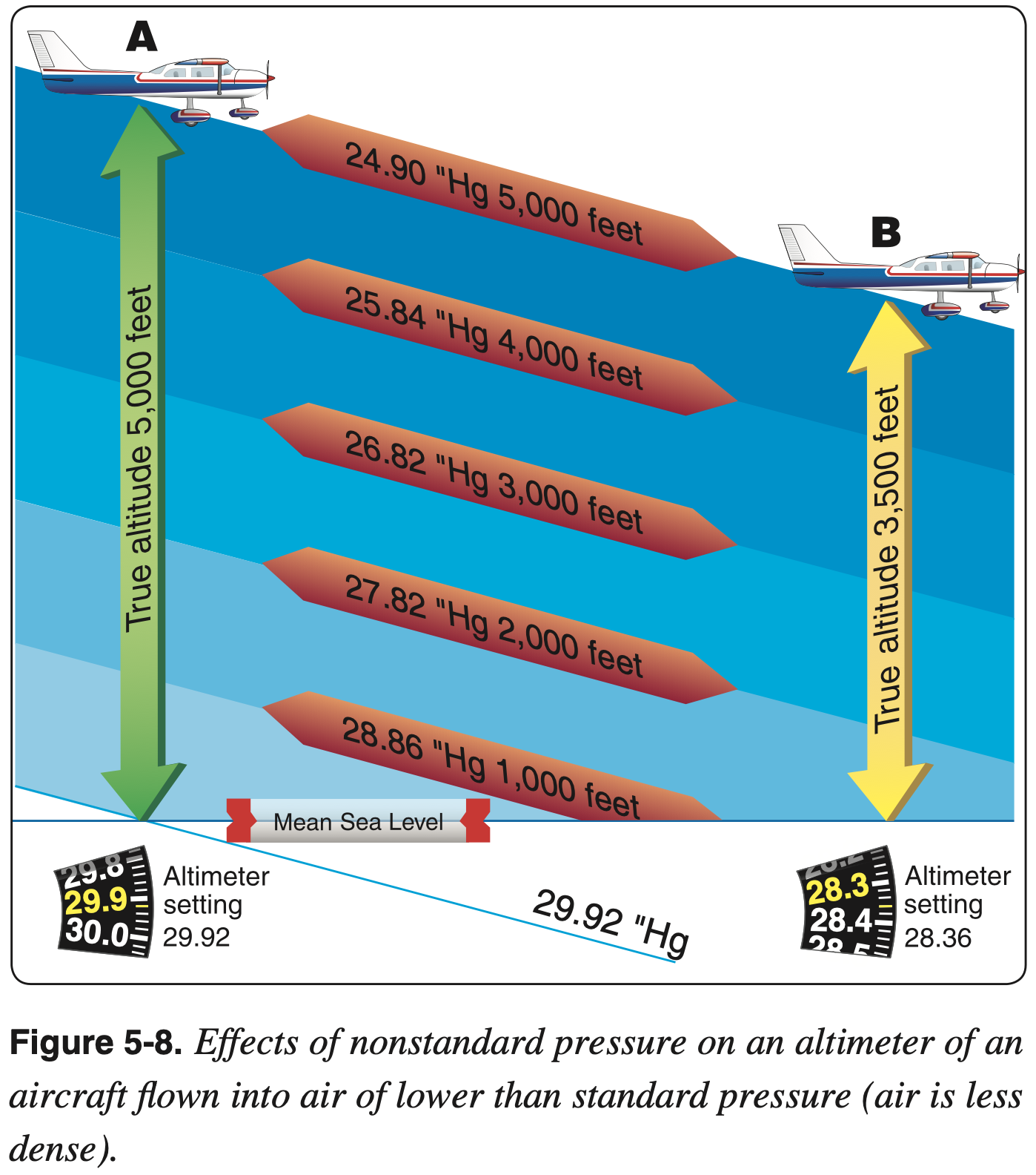
- The indicated altitude is correct, however, only when the sea level barometric pressure is standard (29.92 inHg), the sea level free air temperature is standard (15 °C or 59 °F), and the pressure and temperature decrease at a standard rate with an increase in altitude.
- Can adjust the altimeter for nonstandard pressure but not temperature
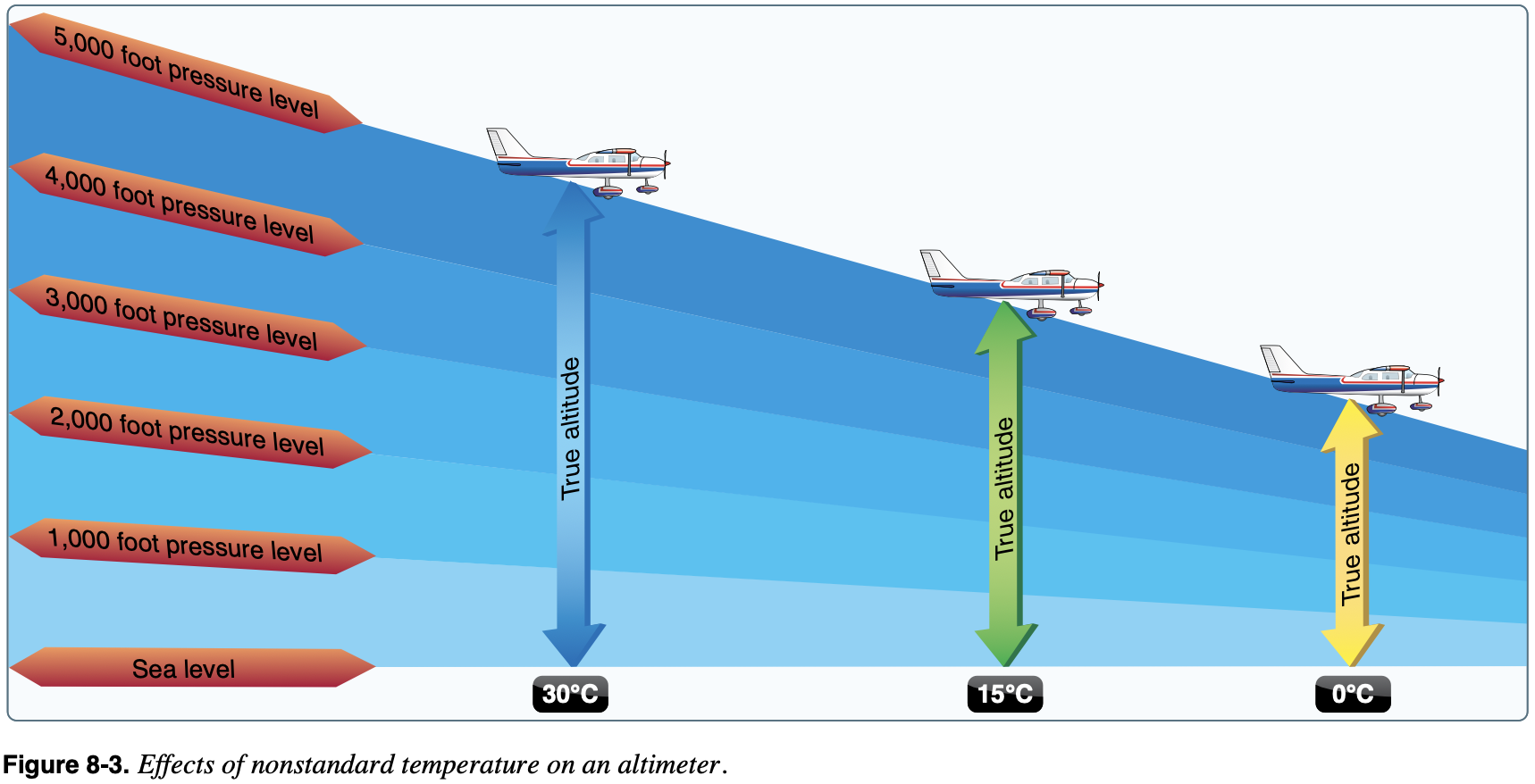
- True altitude thus varies with temperature
- Higher temps means true altitude is higher than indicated and lower temps means true altitude is lower than indicated
- Recall "hot-to-cold look out below"
- Beware obstacle clearance especially when flying in colder temps
- Mental model: altimeter setting provides true datum at ground level of the reporting station. Then consider the pressure gradient (which decreases with altitude). Compared to the standard pressure gradient, the pressure gradient in colder more dense air will decrease more quickly, and in hot air the pressure gradient will decrease less quickly.
Preflight Check
- Reads within 75 feet of field elevation when set to local altimeter setting
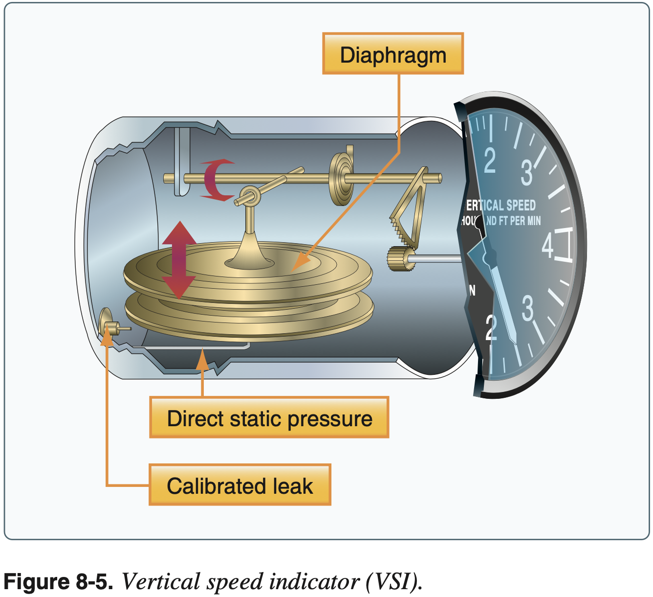
Vertical Speed Indicator (VSI)
- Not required equipment for VFR or IFR flight
- Uses static pressure only
Preflight Check
- Should indicate 0 when on the ground
- If it indicates something other than 0, this value can be used as 0 and then interpret changes from that value
- Should see a small momentary deviation from 0 when changing to alternate static source
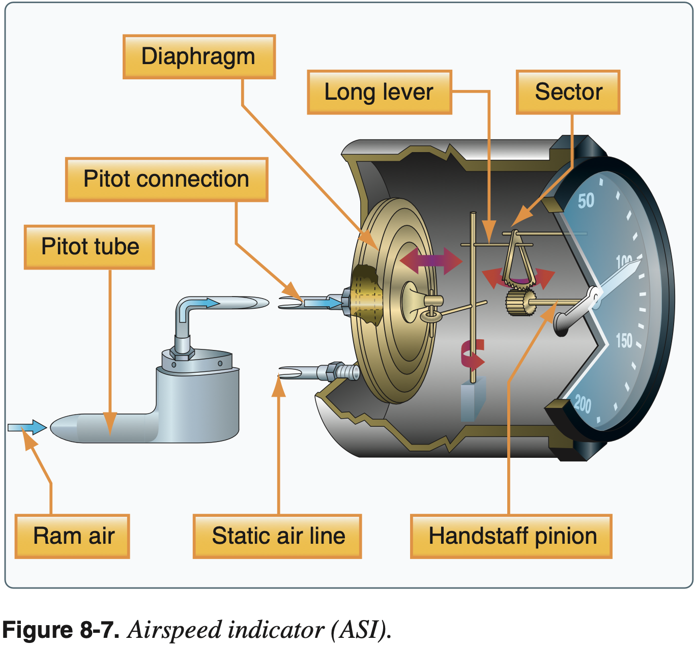
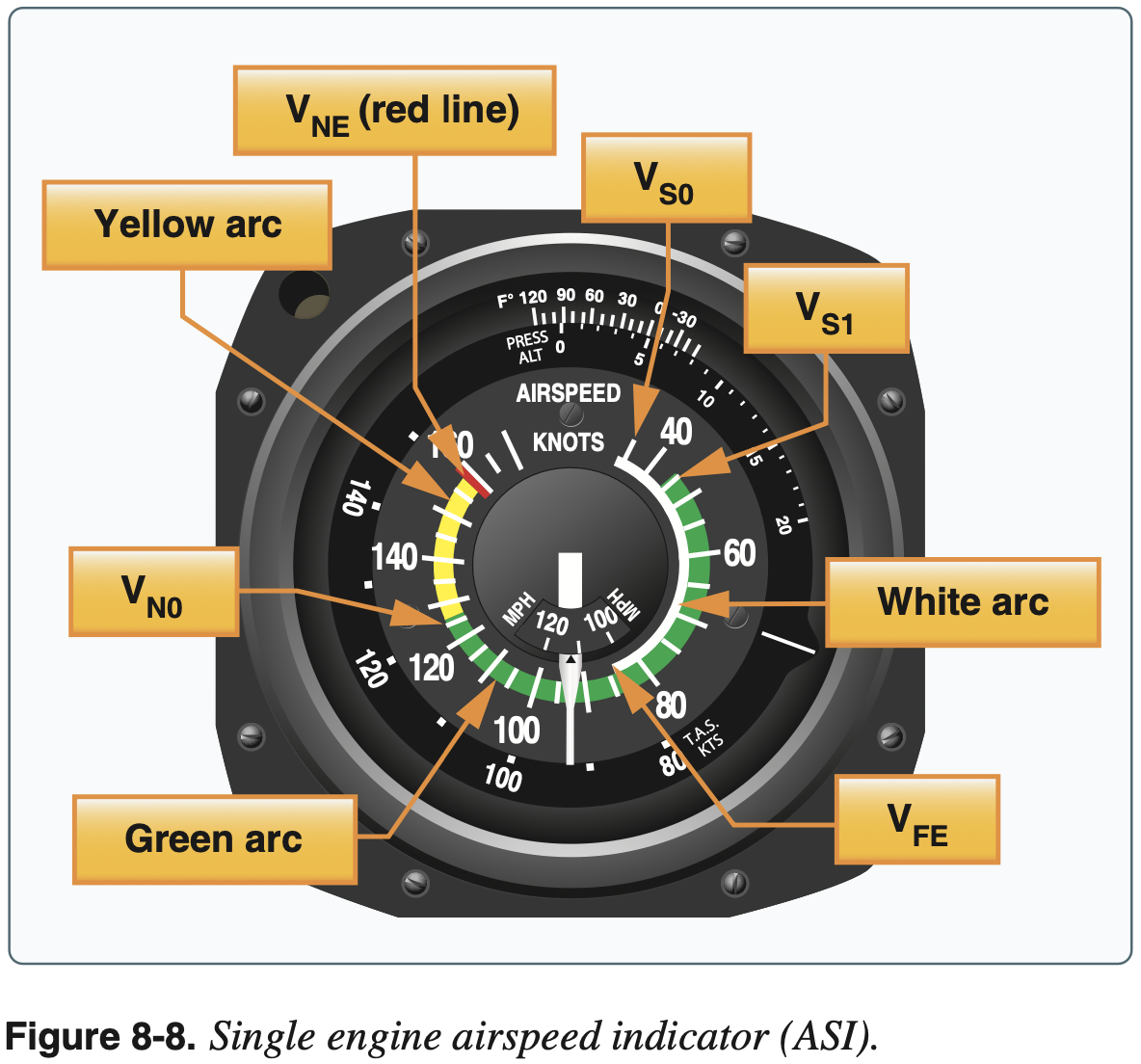
Airspeed Indicator (ASI)
- Requires pitot and static pressure
- Required for day VFR operation
- Lower limits of green and white arc are power-off stall speeds
- Other speeds not here are, for example,
, , and - The same behavior described by "hot-to-cold look out below" for the altimeter applies to the airspeed indicator as well - when flying to a warmer area, for example, true airspeed will increase (given a constant power setting and true altitude)
Preflight Check
- Should read 0 when stationary and while taxiing
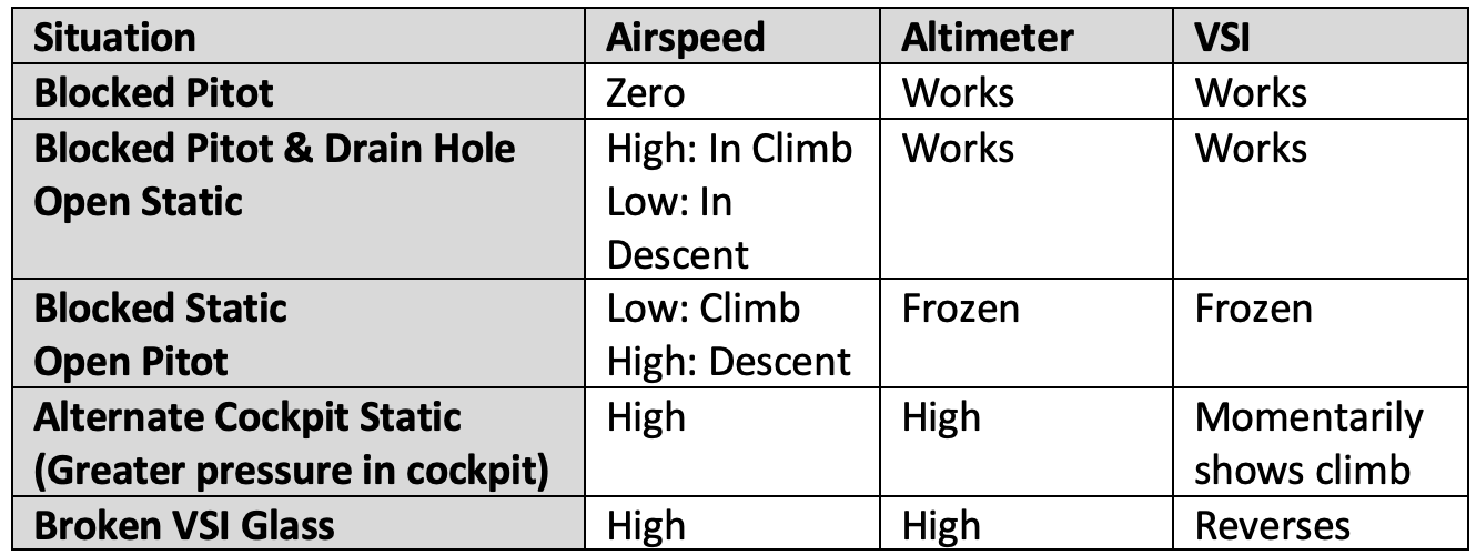
Failure modes
- Alternate static source
- Due to the venturi effect of the air flowing around the fuselage, the air pressure inside the flight deck is lower than the exterior pressure.
Static Pressure
Consider the atmosphere as an ideal gas. The moisture content in the air also affects its density.
From FAA-H-8083-25B Pilot's Handbook of Aeronautical Knowledge Chapter 8: Flight Instruments:
Adjustments to compensate for nonstandard pressure do not compensate for nonstandard temperature. Since cold air is denser than warm air, when operating in temperatures that are colder than standard, the altitude is lower than the altimeter indication.
When flying into a cooler air mass while maintaining a constant indicated altitude, true altitude is lower. If terrain or obstacle clearance is a factor in selecting a cruising altitude, particularly in mountainous terrain, remember to anticipate that a colder-than-standard temperature places the aircraft lower than the altimeter indicates. Therefore, a higher indicated altitude may be required to provide adequate terrain clearance.
When the air is warmer than standard, the aircraft is higher than the altimeter indicates.
For an incompressible fluid the hydrostatic pressure is given by the following, where
TODO@dpwiese - insert picture here so sign of
Using a reference pressure
We can differentiate to get the gradient but basically we can see that at a given height
TODO@dpwiese - insert picture showing these pressure gradients
Gyroscopic Principles
- Principles
- Rigidity in space
- Precession
- These principles areapplicable to understand the gyroscopic action of the propeller as well as gyroscopic instruments.
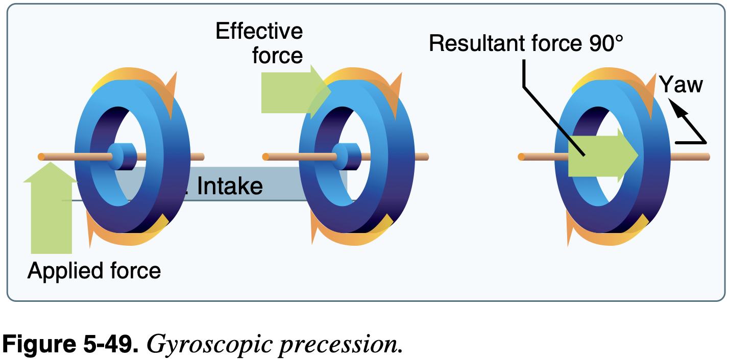
- First consider precession
- Consider a rotating disc.
- moment of momentum (or angular momentum) vector, parallel to rotation - Moment of momentum measures an objects tendency to continue to spin, it describes the rotary inertia of a system in motion about an axis.
- Apply couple (or pure moment)
perpendicular to - Newton's second law for rotation is
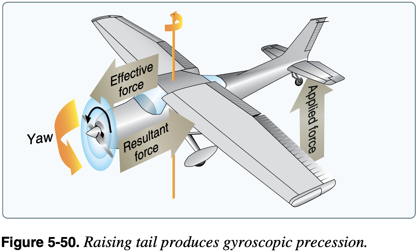
, therefore the angular momentum vector is moving in the direction of - Applying this to an tailwheel aircraft rolling down the runway as it rotates, which is a common instance where this effect can be experienced
is out the nose representing the angular momentum of the spinning propellor, which is spinning clockwise from the pilot's view - A pitch down to raise the tailwheel is a couple
out the left side of the plane - Therefore
is also out of the left side of the plane, meaning the angular momentum is changing towards the left, indicating a left turning tendency
Gyroscopic Instruments
- Principles
- Rigidity in space
- Precession
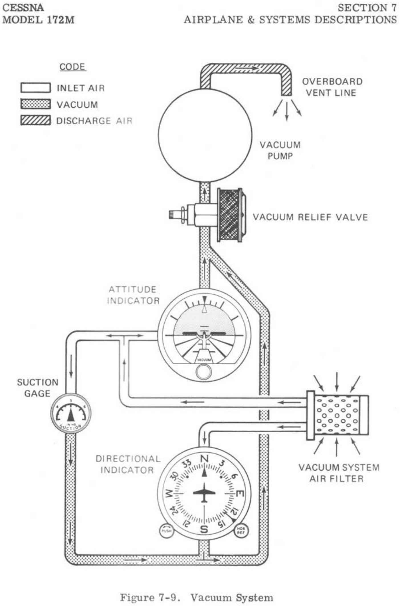
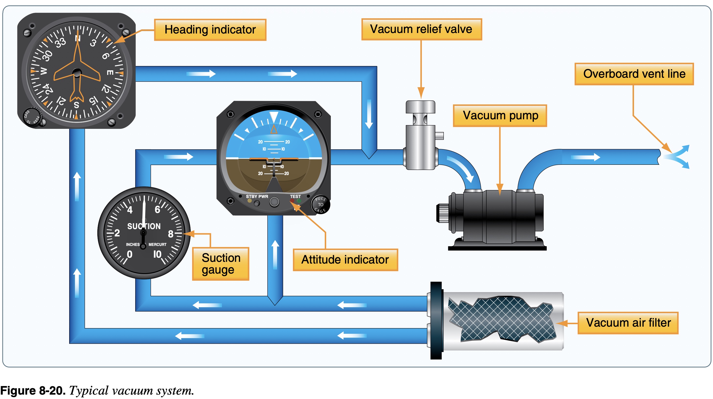
- Electrically or vacuum powered
- What is in POH might have changed and need to consult supplements, e.g. G5 attitude indicator using solid state (electrically powered) gyro instead of vacuum powered.
- Due to friction, gyroscopic instruments can drift and need to be reset periodically (for example heading indicator to compass)
- For example, check and reset every 15 minutes
- Certain gyroscopic instruments have specific pitch and bank limits that induce a tumble of the gyro.
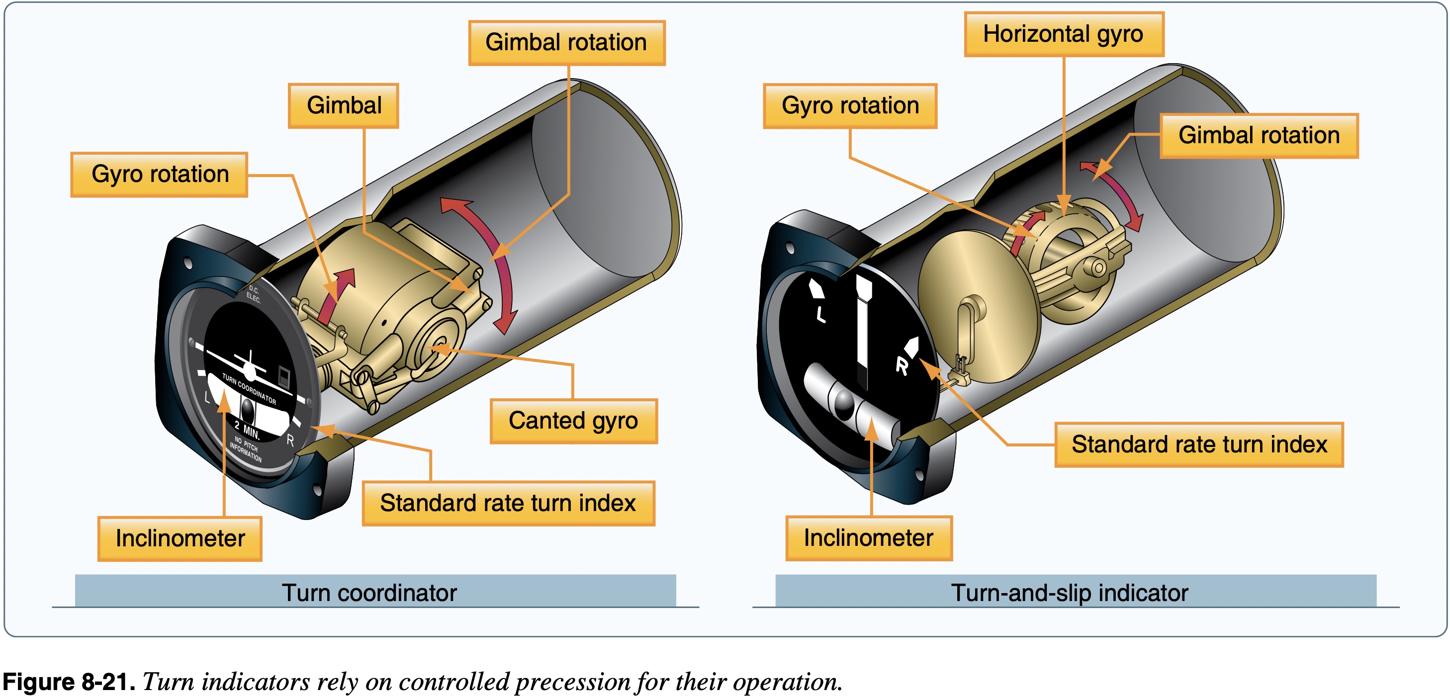
- Turn indicators
- Turn coordinator:
- Roll rate (initially)
- Rate of turn (after it stabilizes)
- Quality of turn
- Contains inclinometer - the ball - "step on the ball" to coordinate flight
- Turn and slip indicator:
- Rate of turn
- Quality of turn
- Turn coordinator:
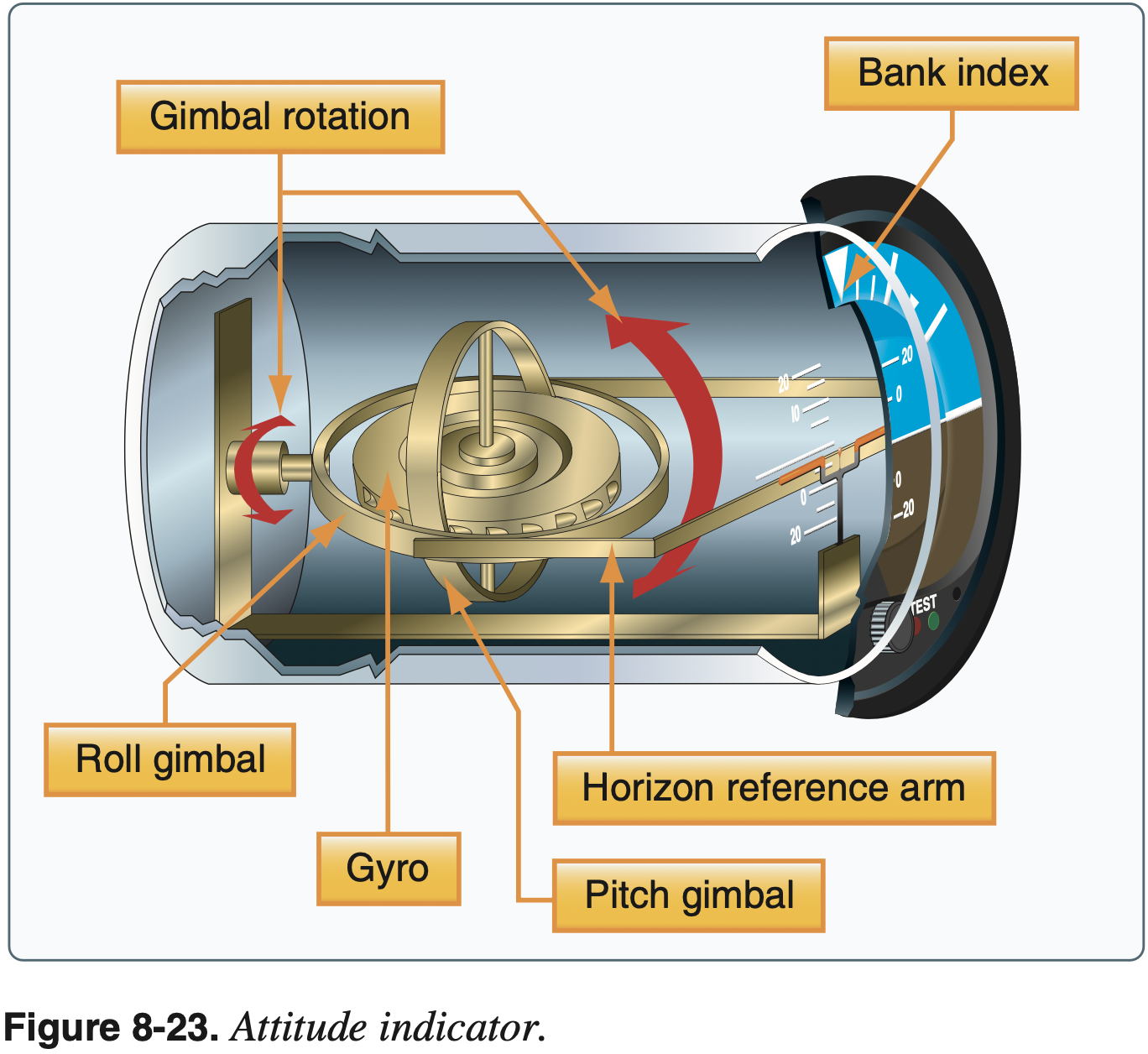
- Attitude indicator
- Also known as artificial horizon
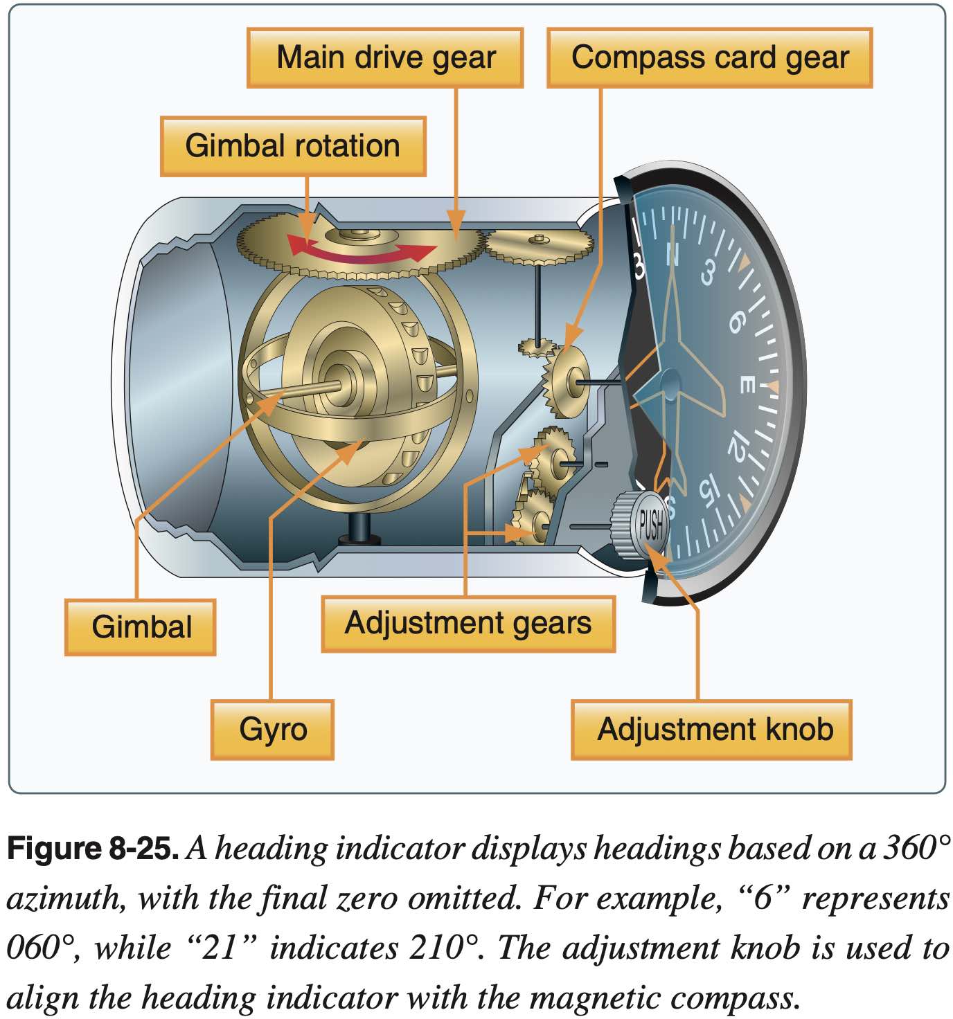
- Heading indicator
- Also known as directional gyro
- Usually powered by the aircraft vacuum system
- Errors in compass make it hard to use to turn to specific headings, especially in turbulent air - heading indicator helps with this
- Some heading indicators referred to as horizontal situation indicators (HSI) receive a magnetic north reference from a magnetic slaving transmitter and generally need no adjustment.
- See also: remote indicating compass
- Radio magnetic indicator (RMI)
- A standard-rate turn is defined as a turn rate of 3° per second (2 minutes to complete a 360 degree turn).
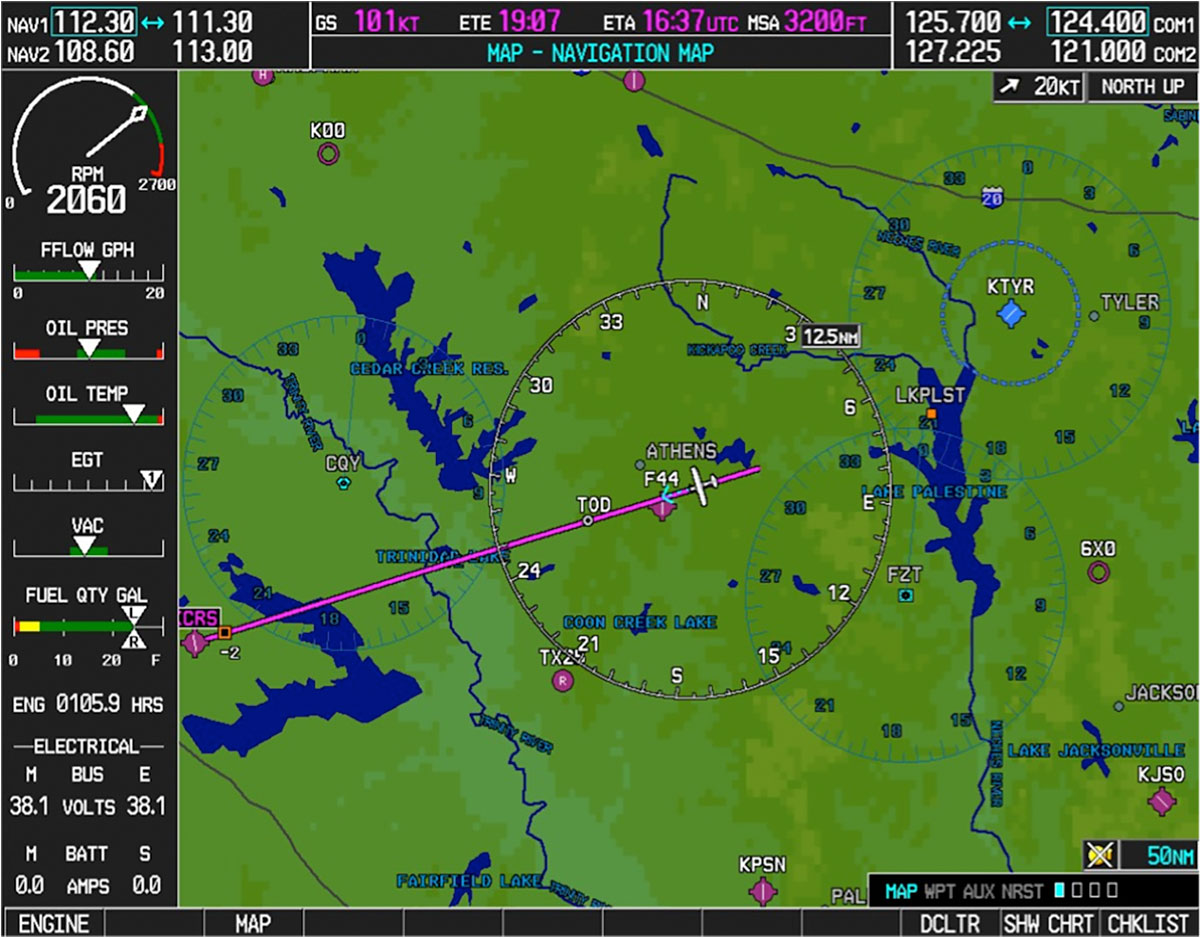
Multifunction Display (MFD)
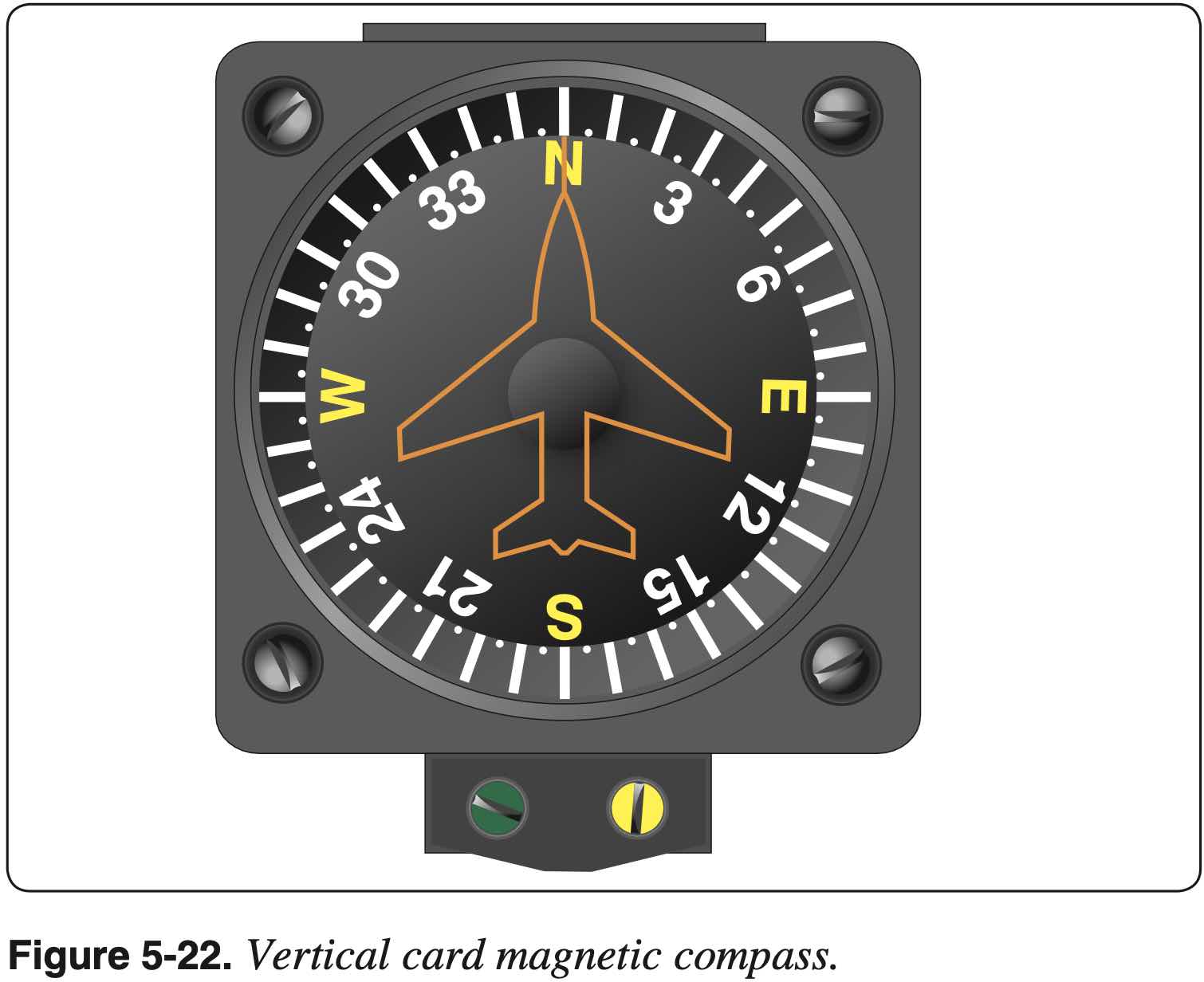
Magnetic Compass
Note: much of the tendencies described below are specific to the northern hemisphere and the opposite behavior would occur in the southern hemisphere.
- Variation
- The difference between true and magnetic directions
- More on magnetic variation below
- Deviation
- Created by local magnetic field around aircraft
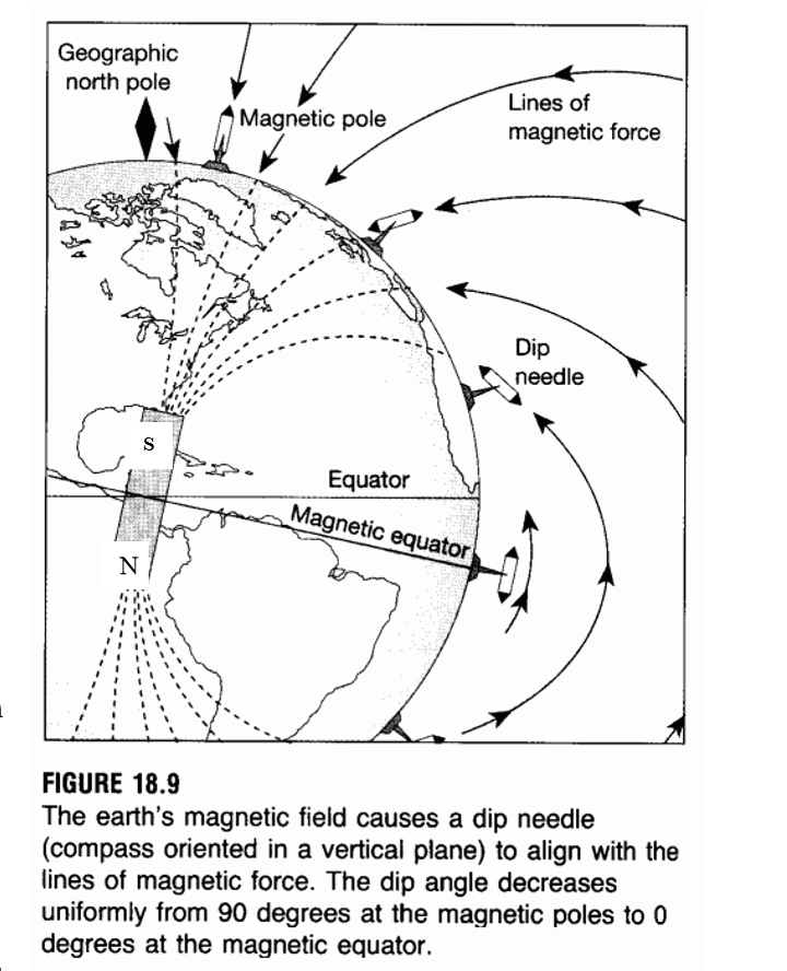
- Dip
- Magnetic field isn't in the plane of the aircraft, so it tends to pull compass down
- Only really an issue near magnetic poles, and minimum at magnetic equator
- Oscillation
- Combination of all other errors
- Acceleration / Turning
- These are related to, or manifestations of dip errors
- Recall ANDS/UNOS
- Accelerate North Decelerate South
- This acronym indicates the error we would see - that is during accelerations on an easterly or westerly heading, we would see the compass falsely turn towards north when accelerating and falsely turn towards south when decelerating.
- Causes errors when accelerating and decelerating on easterly and westerly headings
- Acceleration causes an indication toward north, deceleration causes an indication toward south
- Undershoot North Overshoot South
- When turning from a northerly heading the compass will undershoot and initially show a turn in the opposite direction - undershooting the initial heading change
- When turning from a southerly heading, the compass will overshoot and initially show a turn in the correct direction that is greater than the actual initial heading change
- e.g. a northerly turn should be stopped prior to arrival at the desired heading
The explanation in FAA-H-8083-25B Pilot's Handbook of Aeronautical Knowledge regarding compass dip-correction weights doesn't make sense. It states:
This is done by lowering the center of gravity below the pivot point and making the assembly heavy enough that the vertical component of the magnetic force is too weak to tilt it significantly out of the horizontal plane.
But the next sentence after it states:
Because the dip angle is of no navigational interest, the compass is made so that it can rotate only in the horizontal plane.
So if the compass can only rotate in the horizontal (
In acceleration error, the dip-correction weight causes the end of the float and card marked N (the south-seeking end) to be heavier than the opposite end. When the aircraft is flying at a constant speed on a heading of east or west, the float and card is level. The effects of magnetic dip and the weight are approximately equal. If the aircraft accelerates on a heading of east [Figure 3-21], the inertia of the weight holds its end of the float back and the card rotates toward north. As soon as the speed of the aircraft stabilizes, the card swings back to its east indication. If, while flying on this easterly heading, the aircraft decelerates, the inertia causes the weight to move ahead and the card rotates toward south until the speed again stabilizes.
It's also not reasonable to expect that compass technology has changed in the 8 years between the current and former edition of the PHAK. But more importantly, there is no physical basis for the explanation in the current PHAK. Also browsing Aircraft Spruce, the compasses require selection of northern or southern hemisphere, indicating presumably the asymmetric dip-correction weight.
There seem to be other compass types, and different ways to accommodate dip error without a weight on one of the compass "seeking" ends. However, for the purposes of understanding compass errors, the mental model of a weight opposite the "seeking" end is probably the best.
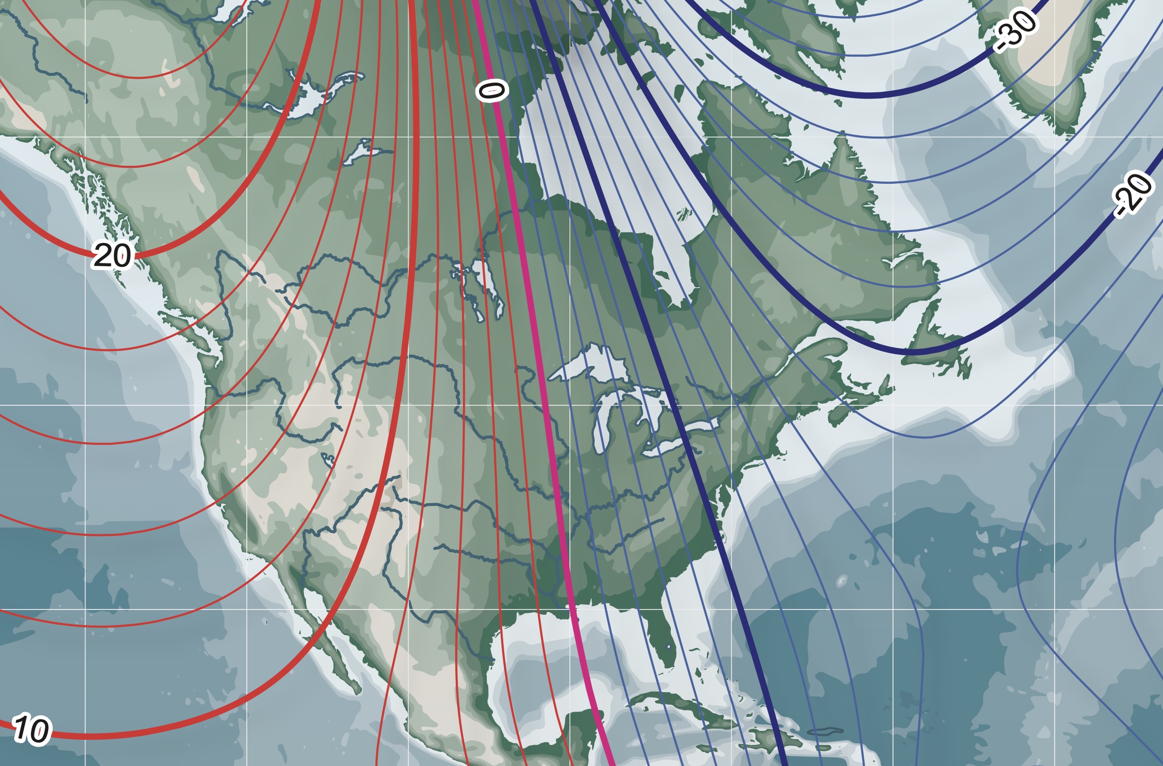
Magnetic Variation
- The E/W variation on isogonic lines indicates where you would end up relative to true north if you followed your compass north.
- Thinking back to private pilot flight planning with the flight plan form and manually charting on a sectional chart, we want to navigate based on true directions. If magnetic north and true north were collocated, life would be good. They are not, so we need to correct for magnetic directions so that we can navigate by true directions.
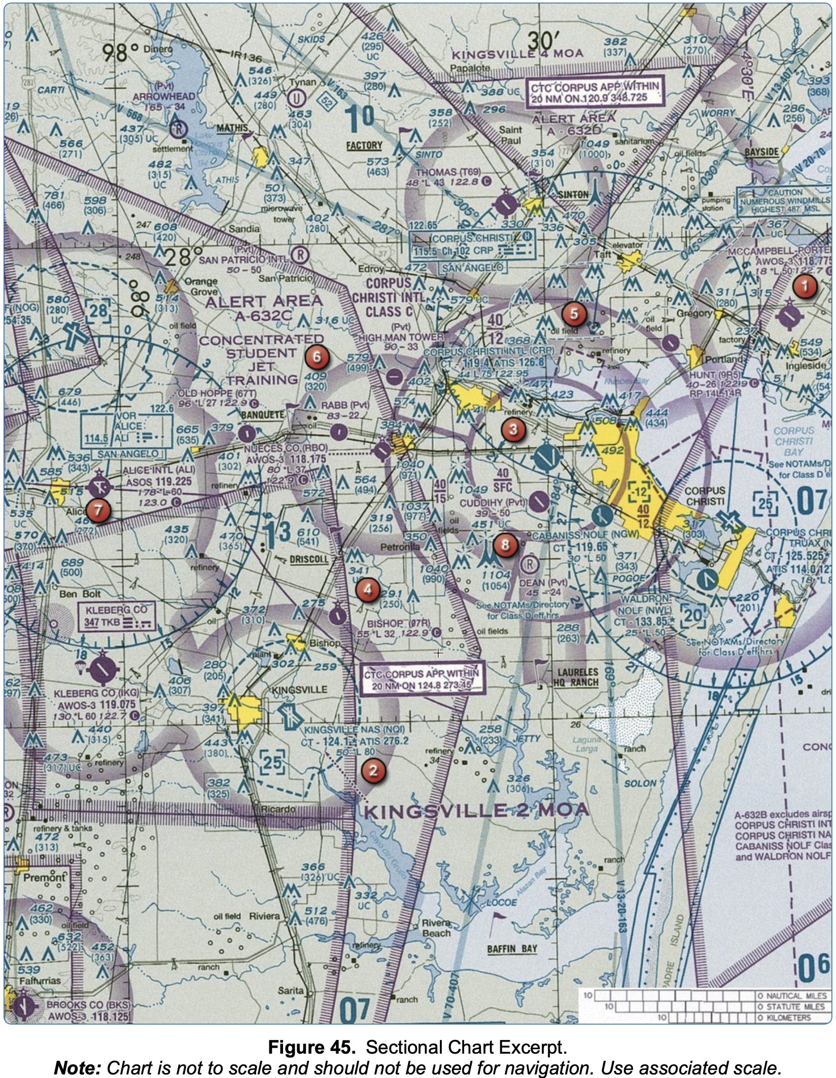
- Note: Figure 45 in the FAA-CT-8080-5H Instructor Knowledge Test Supplement shows the sectional chart around Corpus Christi TX and easterly magnetic variation, in case that is helpful to remember anything on the test.
- By convention, magnetic variation is positive when magnetic north is east of true north, and negative when it is to the west.
- In other words, if we are trying to fly to true north from Corpus Christi (which indicates an easterly magnetic variation) using our compass, we would end up east of true north. This is how to think about easterly / westerly magnetic variation - it's where you would end up relative to true north if you followed your compass north.
- So, in this case we would need a more westerly heading to actually end up at true north.
- TC +W/-E Var = MC +R/-L WCA = MH (this is what we do on flight plan form)
- Remember for the test it is subtract E and L and add W and R when going from TC to MC
- It is the opposite when going the other way
- When measuring true course on a line drawn on a sectional chart, measure the course angle at the midpoint of the line
- The
Kidentifier in front of airports is for ICAO recognized airports that are located in the contiguous United States
References
- FAA-H-8083-15B Instrument Flying Handbook
- Chapter 5: Flight Instruments
- Page 5-28: Multi-Function Display (MFD)
- Chapter 5: Flight Instruments