Navigation Equipment
This page covers the portion of Task A. Aircraft Flight Instruments and Navigation Equipment from the FAA-S-8081-9E Flight Instructor Instrument Practical Test Standards pertaining to navigation equipment and their operating characteristics.
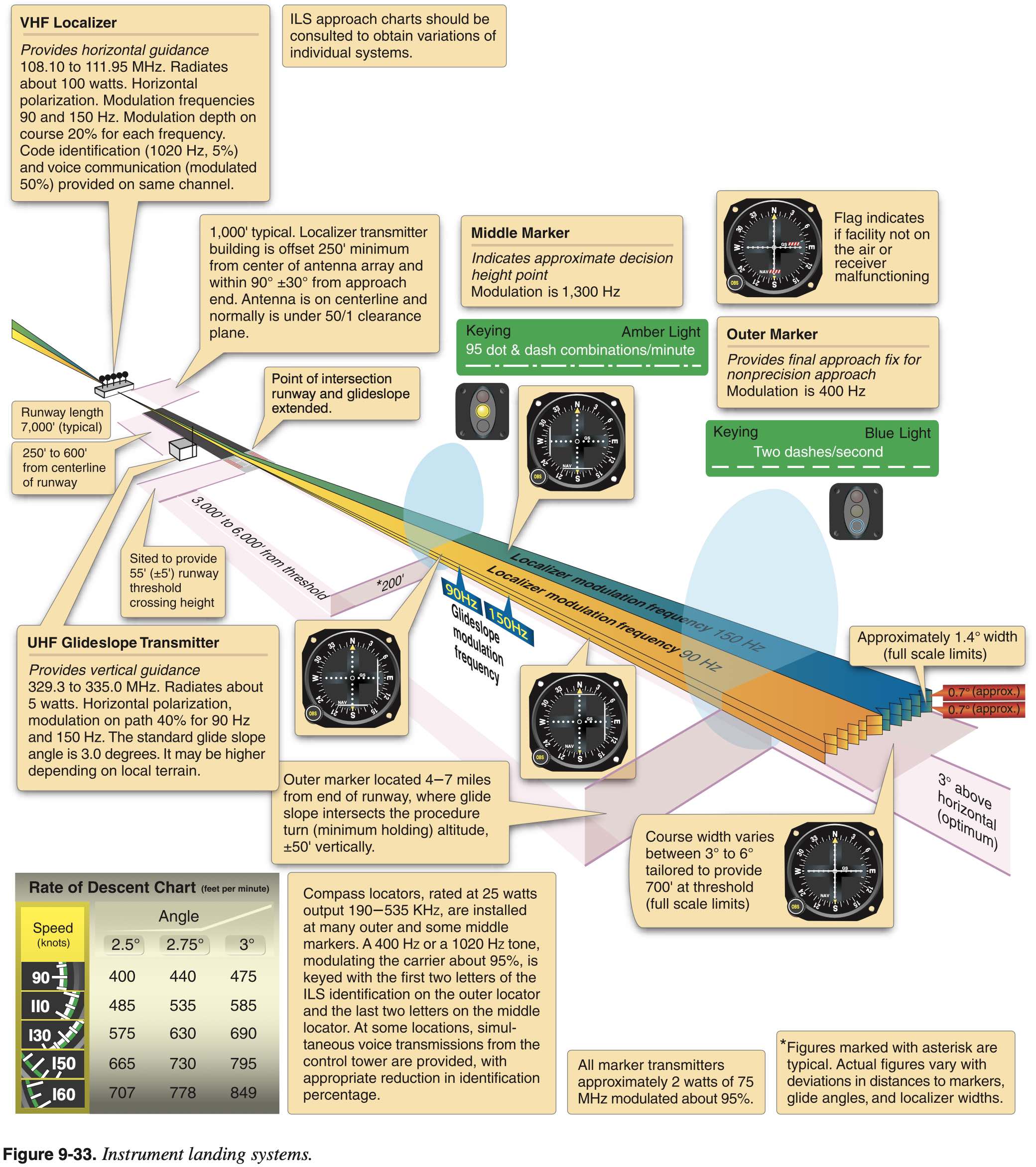
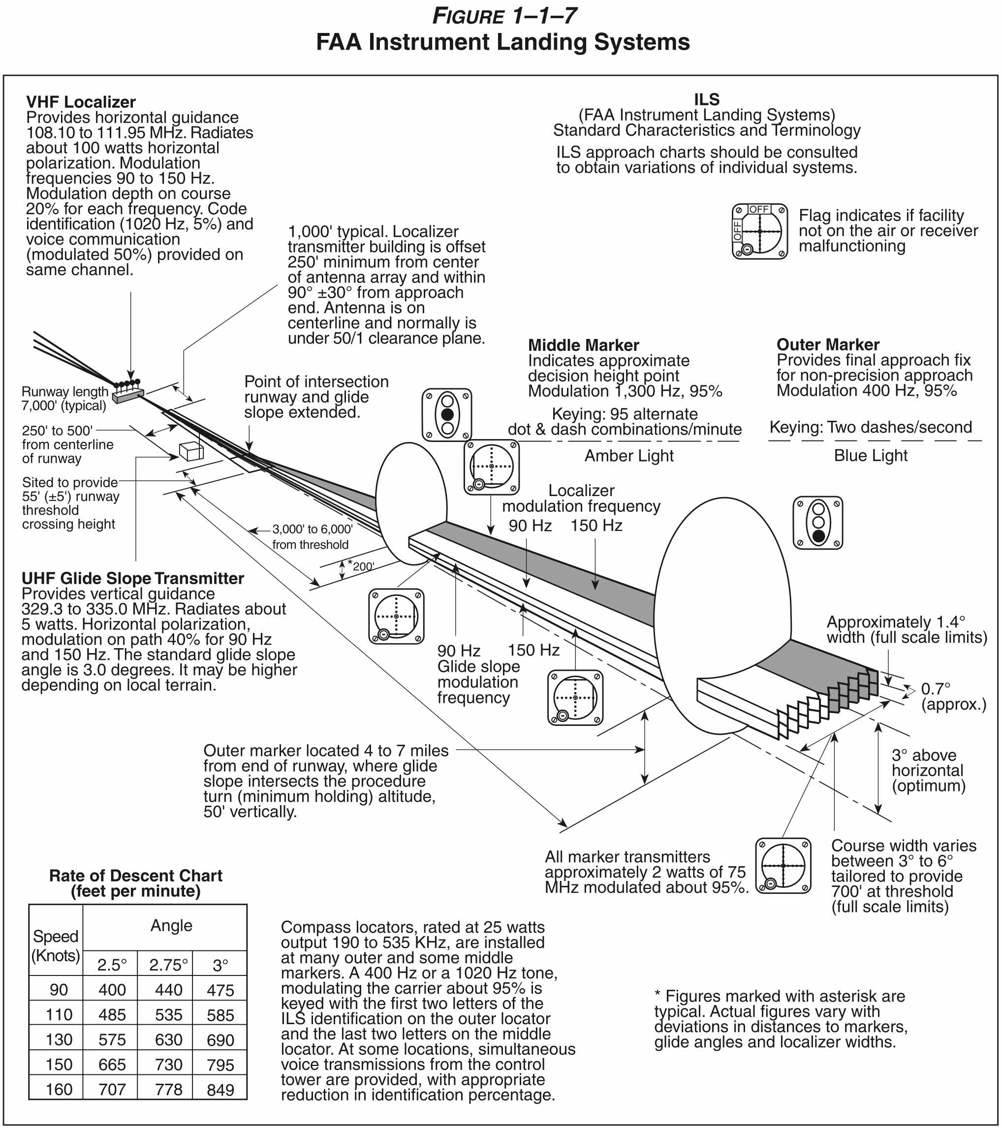
Instrument Landing System (ILS)
- Provides
- Guidance information
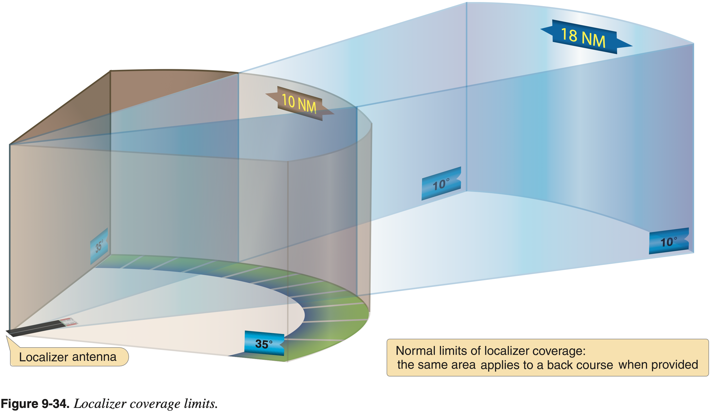
- Localizer
- Up to 18 nm
- Glide slope
- Up to 10 nm
- Localizer
- Range information
- Marker beacons
- See below
- DME
- Marker beacons
- Visual information
- Approach lights
- Runway and touchdown lights
- Guidance information
- Marker beacons
- Outer Marker (OM)
- Indicates the final approach fix (FAF) / glideslope intercept
- Middle Marker (MM)
- Usually 3,500 ft from landing threshold
- Glideslope 200 ft above touchdown zone elevation
- Inner Marker (IM)
- For Category II ILS
- Outer Marker (OM)
What are the dimensions of an ILS?
- Localizer: Usually 5° total width, with the width at the threshold being 700 feet.
- Glideslope: Usually a 3° slope, with 1.4° total width.
When can you descend to the next instrument approach segment?
- When cleared for the approach and established on a segment of a published approach or route.
Marker Beacon Receiver / Indicators
- Outer Marker (OM)
- Indicates glideslope intercept
- Middle Marker (MM)
- Usually 3,500 ft from landing threshold
- Glidepath 200 ft above touchdown zone elevation
- Inner Marker (IM)
- For Category II ILS
Nondirectional Radio Beacon (NDB) / Automatic Direction Finder (ADF)
- FAA-H-8083-15B Instrument Flying Handbook
- Chapter 9: Navigation Systems
- Page 9-3: Nondirectional Radio Beacon (NDB)
- Chapter 9: Navigation Systems
- AIM 1-1-2 Nondirectional Radio Beacon (NDB)
- A low or medium frequency radio beacon transmits nondirectional signals whereby the pilot of an aircraft properly equipped can determine bearings and "home" on the station
- These facilities normally operate in a frequency band of 190 to 535 kilohertz (kHz)
- Information from an NDB is displayed to the pilot on an Automatic Direction Finder (ADF) of which there are four kinds
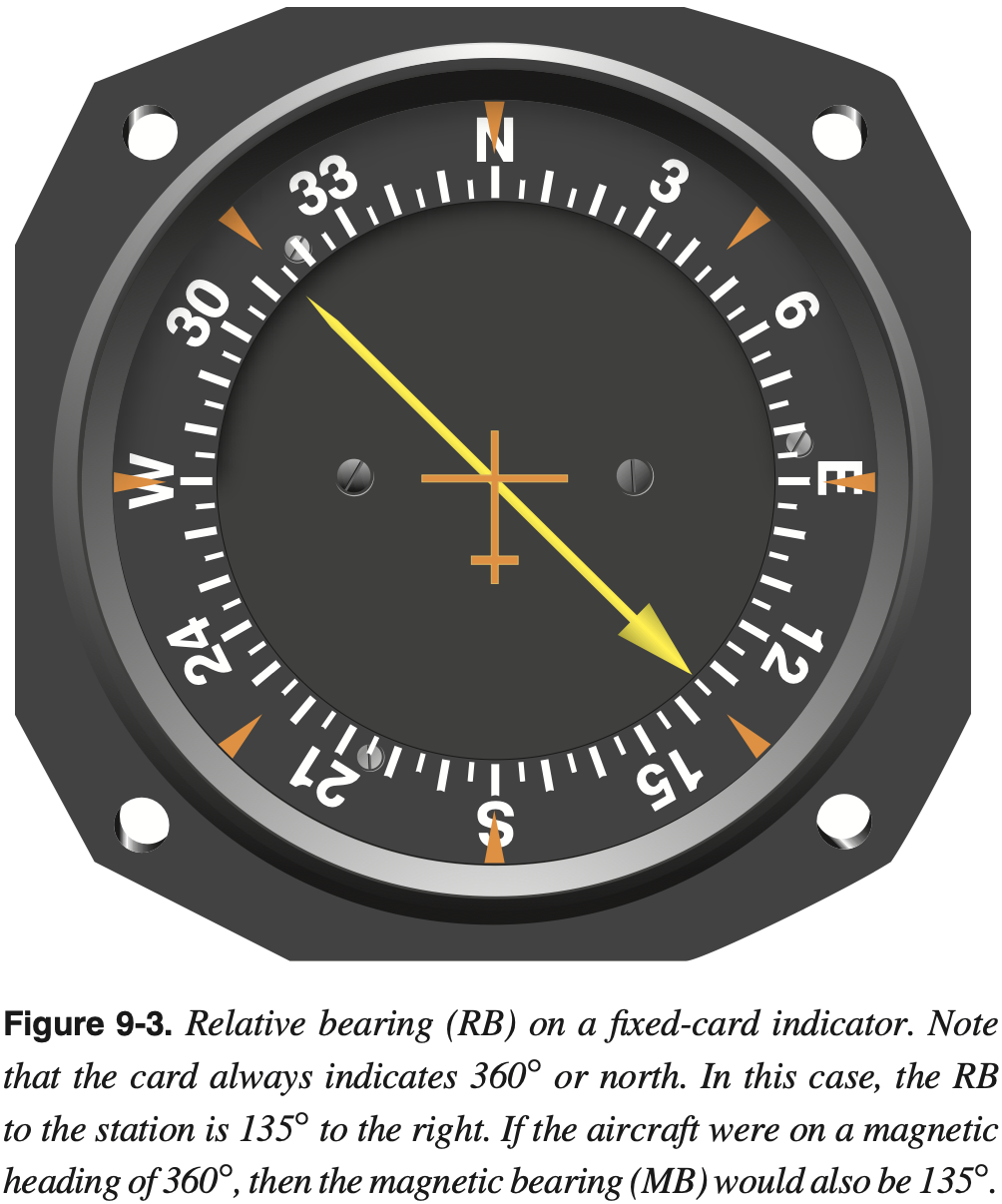
- Fixed-card ADF also known as the relative bearing indicator (RBI)
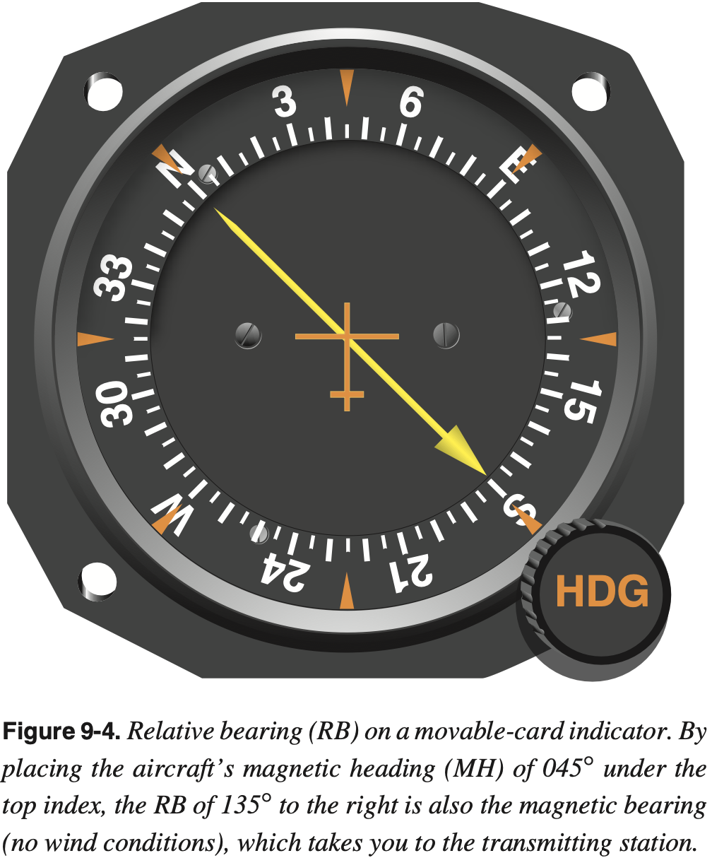
- Rotatable compass-card ADF
- Radio magnetic indicator (RMI) (with either one needle or dual needle)
- All radio beacons, except compass locators, transmit a continuous three-letter identification in code, except during voice transmissions
- NDBs have one advantage over the VOR in that low or medium frequencies are not affected by line-of-sight
- If the aircraft is within the range of the station, the signals can be received regardless of altitude
- One of the disadvantages that should be considered when using low frequency (LF) for navigation is that LF signals are very susceptible to electrical disturbances, such as lightning.
- The ADF needle points TO the station, regardless of aircraft heading or position.
- Navigating to an NDB
- Homing
- Tracking
Transponder
- A transponder is a radar beacon transmitter/receiver installed in the instrument panel.
- ATC beacon transmitters send out interrogation signals continuously as the radar antenna rotates.
- When an interrogation is received by a transponder, a coded reply is sent to the ground station where it is displayed on the controller's scope.
- A reply light on the transponder panel flickers every time it receives and replies to a radar interrogation. Transponder codes are assigned by ATC.
- Transponders used in general aviation are mode A
- If it can do altitude encoding it has mode C capability
- Mode C sends pressure altitude to ATC
- Adjusting the altimeter's Kollsman window has no effect on the altitude read by the controller.
- A transponder code consists of four numbers from 0 to 7 (4,096 possible codes)
- Mode S transponder sends/receives some extra data
- Mode S offers improvements over Mode C
- 24-bit addresses instead of 4-bit
- Transmits more data
- Aircraft Collision Avoidance System (ACAS)
- Heading, roll angle, etc.
Requirements
- Must have transponder with mode C in
- Class A, B, and C airspace
- Above 10,000 MSL, except when 2,500 AGL.
- Within 30 nm of class B primary airports (in and above the mode-C veil)
- Within 10 nm of certain designated airports, excluding airspace which is both outside the Class D surface area and below 1,200' AGL
- Flying into, within, or across the ADIZ
Comparison Against ADS-B Requirements
- Mode-C is required in the same places as ADS-B except it is all airspace at or above 10,000 feet MSL, excluding airspace at and below 2,500 feet AGL (not just class E).
- Mode-C is not required in the Gulf of Mexico area specified for ADS-B.
- Mode-C is required into/within/across the ADIZ
ADS-B
ADS-B
A surveillance technology in which an aircraft determines its position via satellite navigation or other sensors and periodically broadcasts it, enabling it to be tracked.
- ADS-B uses plane's WAAS GPS and broadcasts information to other planes and ground stations.
- Ground stations compile and rebroadcast received information.
- This is known as ADS-B Out.
- ADS-B In is the capability for other planes to receive this information as traffic, as well as weather information.
- Acronym
- Automatic - no pilot input required
- Dependendent - requires positon input, e.g. WAAS GPS
- Surveilance - provides aircrafts location, direction, and climb/descent indication
- Broadcast - broadcasts the surveilance information to be seen by others
- Components of ADS-B In
- Traffic Information Services-Broadcast (TIS-B)
- Provides traffic information to planes with ADS-B receivers.
- The traffic includes that which is not broadcasting its own output via ADS-B, because it's able to use radar data and conventional transponder data to understand where aircraft are.
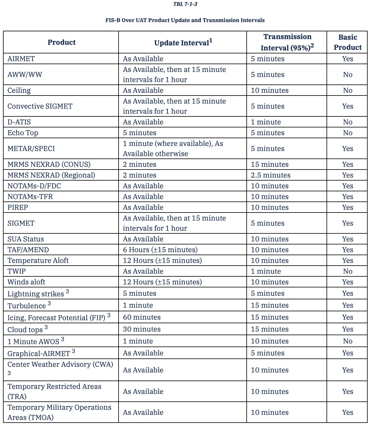
- Flight Information Services-Broadcast (FIS-B)
- Provides NEXRAD graphical weather in (for example in G1000).
- Also provides info on SUA and TFRs.
- Traffic Information Services-Broadcast (TIS-B)
- FAA Automatic Dependent Surveillance-Broadcast (ADS-B)
- FAA Equip ADS-B
- 978 and 1090 MHz
FIS-B
Requirements
- ADS-B is required in:
- Class A, B, and C airspace.
- Class E airspace at or above 10,000 feet MSL.
- Excluding airspace at and below 2,500 feet AGL.
- Within 30 nautical miles of a Class B primary airport (the Mode C veil).
- Above the ceiling and within the lateral boundaries of Class B or Class C airspace up to 10,000 feet.
- Class E airspace over the Gulf of Mexico, at and above 3,000 feet MSL, within 12 nm of the U.S. coast.
- 14 CFR §91.225 - Automatic Dependent Surveillance-Broadcast (ADS-B) Out equipment and use
- 14 CFR §91.227 - Automatic Dependent Surveillance-Broadcast (ADS-B) Out equipment performance requirements
Automatic Pilot
- Electrically powered actuators connected to primary flight controls
- 2-axis: roll and pitch
- Basic control system that can automatically fly a flight path
Deicing and Anti-icing
Airframe
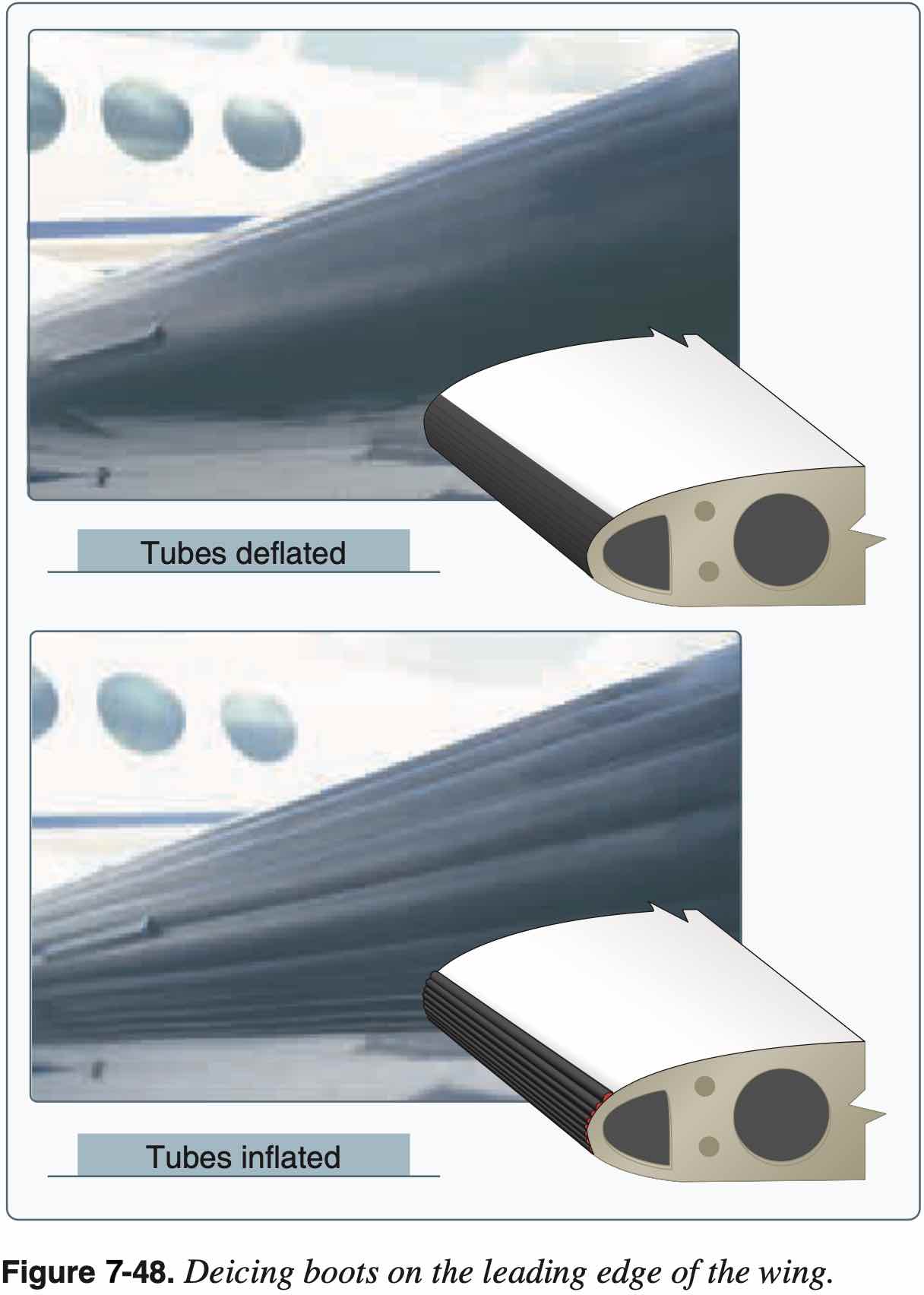
- Wings
- Boots
- Use as soon as icing is observed
- Heated leading edge
- Also called "hot wing"
- Uses hot air from turbine compressor, for example
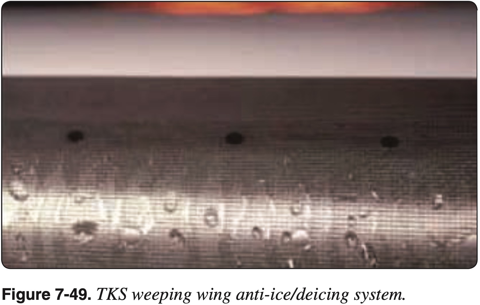
- Weeping wing
- Deicing fluid (e.g. TKS fluid, like antifreeze) comes out of small holes in leading edge
- TKS (Tecalemit-Kilfrost-Sheepbridge Stokes) was the name of a British aerospace company during WWII that developed the original weeping wing technology
- Boots
- Windscreen
- Alcohol
- Hot air defrost
- Electric (like rear window of car)
- Icing fluid from prop in single engine also sprays back on windscreen
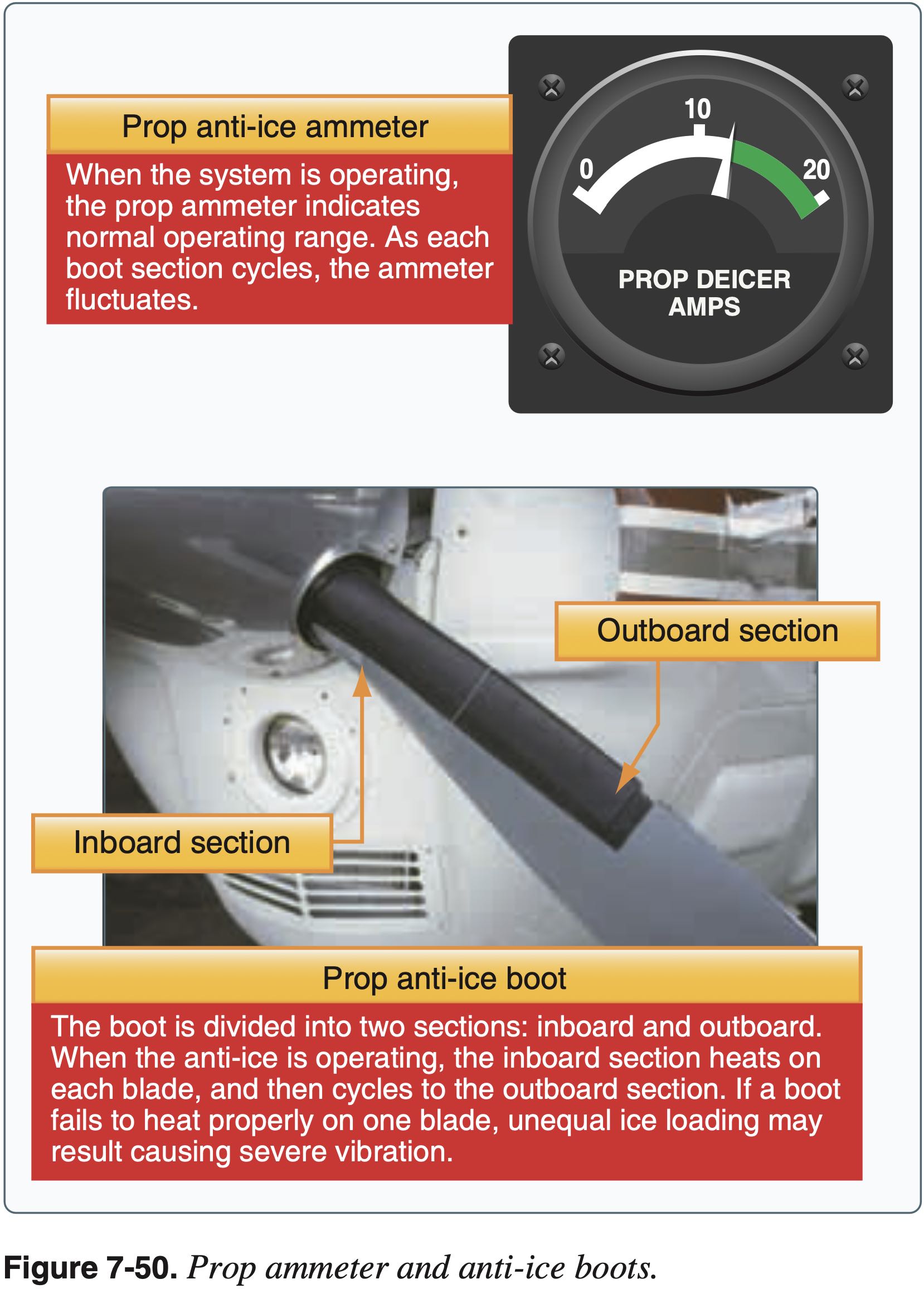
Propellor or Rotor
- Propellor
- Alcohol
- Electric heating element
- Boots
Air Intake
- Carb heat
- Spring-loaded air-filter bypass door
- Alternate air
Fuel System
- Check for water in fuel during preflight
Pitot-Static System
- Pitot heat
- Alternate static source
Encountering Icing
- Exit area of icing
- Generally climb
- To find temps colder than -20 °C
- Being higher gives more options
- Alternatively descend to find temperatures warmer than 5 °C
- Gentle maneuvers
- Avoid increasing load factor too much
- Fly faster
- Avoid configuration change
- No flaps to avoid tailplane stall
Icing Regulations
Known icing conditions
- Note: Part 91 was updated since this letter to include 14 CFR §91.527
"Known icing conditions" involve instead circumstances where a reasonable pilot would expect a substantial likelihood of ice formation on the aircraft based upon all information available to that pilot.
Whether a pilot has operated into known icing conditions contrary to any limitation will depend upon the total information available to the pilot, and his or her proper analysis of that information in evaluating the risk of encountering known icing conditions during a particular operation.
Atmospheric conditions in which the formation of ice is observed or detected in flight. Note-Because of the variability in space and time of atmospheric conditions, the existence of a report of observed icing does not assure the presence or intensity of icing conditions at a later time, nor can a report of no icing assure the absence of icing conditions at a later time.
Radar / Lightning Detection System
- Radar weather can be either onboard or ground-based, and transmitted to the aircraft.
- Onboard weather radar systems
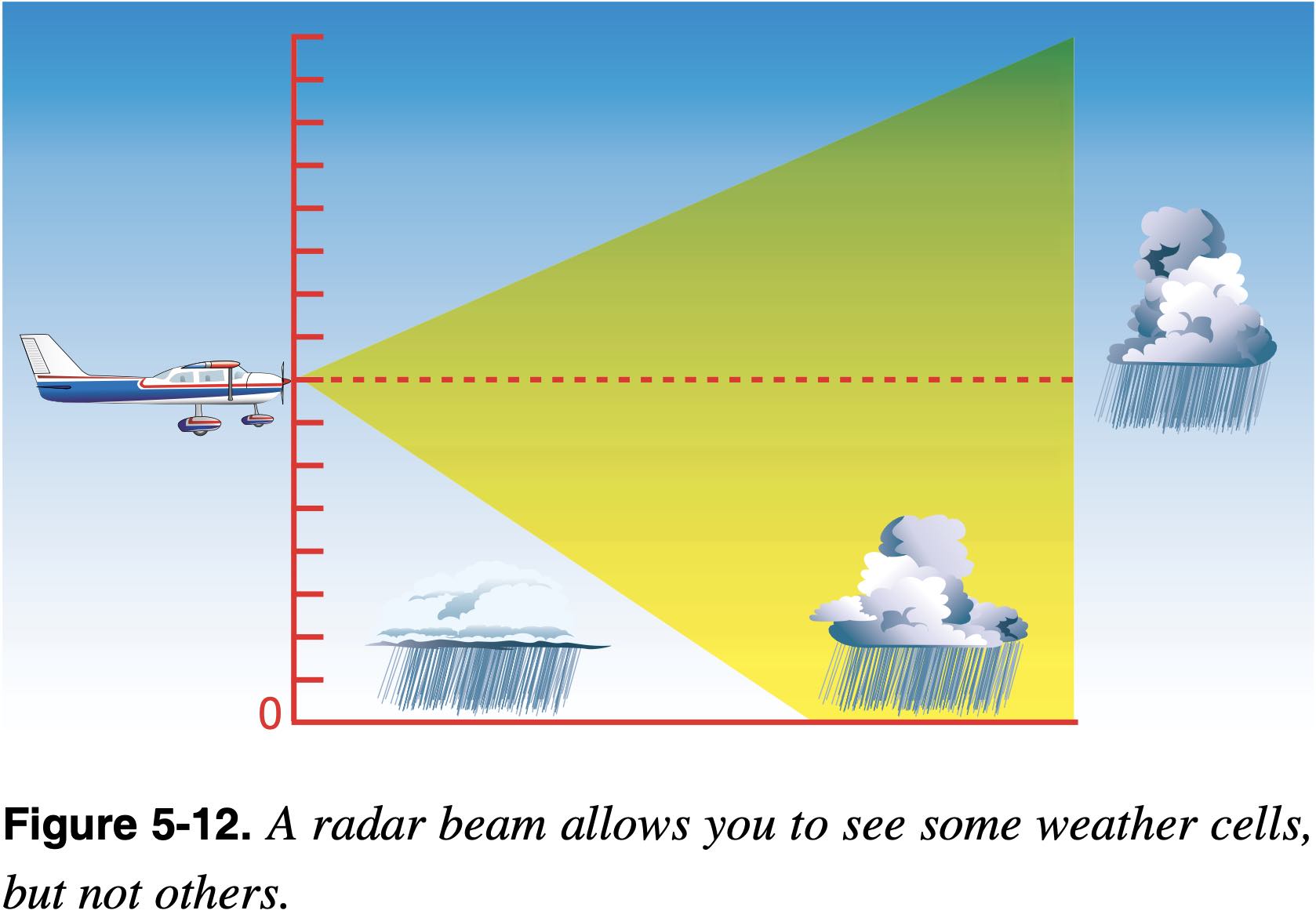
- Onboard weather radar uses an adjustable aircraft mounted radar antenna to detect, in real time, weather phenomena near the aircraft.
- You must be careful not to assume that the only cells in the area are the ones shown on the radar display.
- When a cell is detected by an onboard weather radar system, that cell often absorbs or reflects all of the radio signals sent out by the radar system. This phenomenon, called attenuation, prevents the radar from detecting any additional cells that might lie behind the first cell.
- Ground weather surveillance radar
- Ground weather surveillance integrates weather information from many ground radar stations.
- The weather information collected from many sources is then used to create a composite picture that covers large volumes of airspace.
- These composite radar images can then be transmitted to aircraft equipped with weather data receivers.
- Limitations
- Weather radar does not detect most other kinds of hazardous weather such as fog, icing, and turbulence.
- A second limitation of weather radar is that the earliest (cumulus) stage of a thunderstorm is usually free of precipitation and may not be detected by radar.
- Onboard weather radar systems
- Lightning detection
- Can also come from source onboard the aircraft or on the ground
- An onboard lightning detection system consists of a simple antenna and processing unit that senses electrical discharges in the atmosphere and attempts to determine which electromagnetic signals have the "signature" of lightning strikes.
- See Stormscope and Strikefinder as examples
Other Inflight Weather Systems
- FIS-B or XM Weather can get METAR and TAF in the plane from ground-based sources