Navigation Systems and Radar Services
This page covers Task B. Navigation Systems and Radar Services from the FAA-S-ACS-6C Private Pilot Airman Certification Standards.
Ground Based Navigation
VOR
Overview
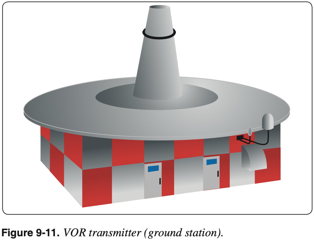
VOR
Very High Frequency (VHF) Omni-directional Range (VOR) is a type of radio based navigation system that allows aircraft to determine their position relative to a ground based antenna.
- AIM 1-1-3 VHF Omni-directional Range (VOR)
- VOR is a ground-based station which broadcasts signals that a plane can receive that indicates a radial that is the magnetic bearing to the station.
- VOR frequencies are standardized in the very high frequency (VHF) band between 108.00 and 117.95 MHz.
- The Omnibearing Selector (OBS) (also referred to as the course selector) is a dial that can be rotated to select a desired course.
- Inside the cockpit, the frequency corresponding to a particular VOR is input and the VOR indicator displays information about where the aircraft is relative to that VOR.
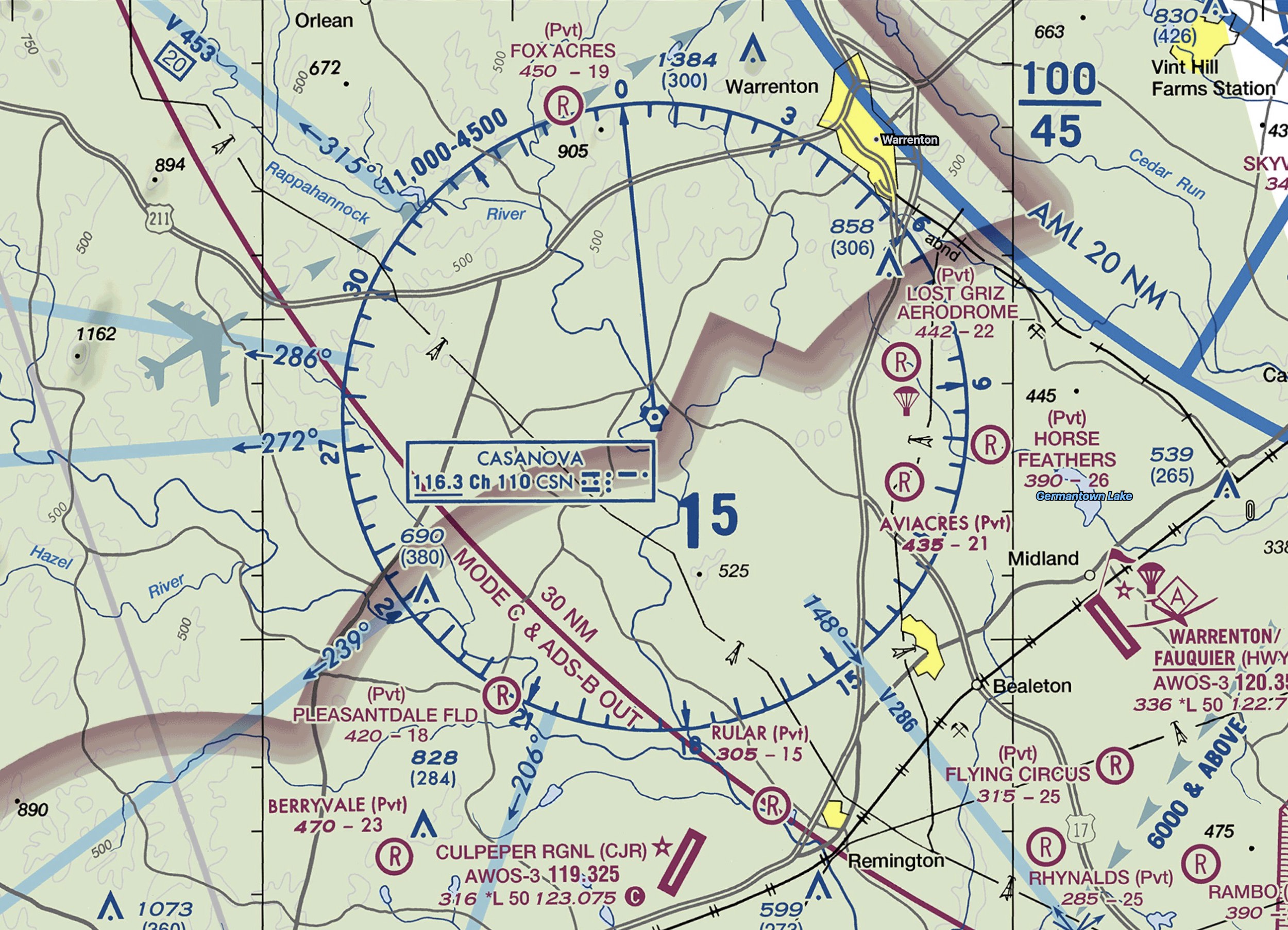
- Radials are projected outward from the station.
- However, any radial can be picked up regardless of where the aircraft is relative to the VOR.
- For example, if we are south of the Casanova VOR, we can pick up the 360° radial that is projected northward from the station.
- The information provided by a VOR alone is independent of the heading of the aircraft.
- In addition to the radial information, we also get information as to whether the selected course will take us to or from the station.
- So in the example above about being south of Casanova VOR, if we dialed the 180° radial we would see a
FROMindication, but if we dialed in the 360° radial we would seeTO. - Remember this information is irrespective of the aircraft's heading.
- So in the example above about being south of Casanova VOR, if we dialed the 180° radial we would see a

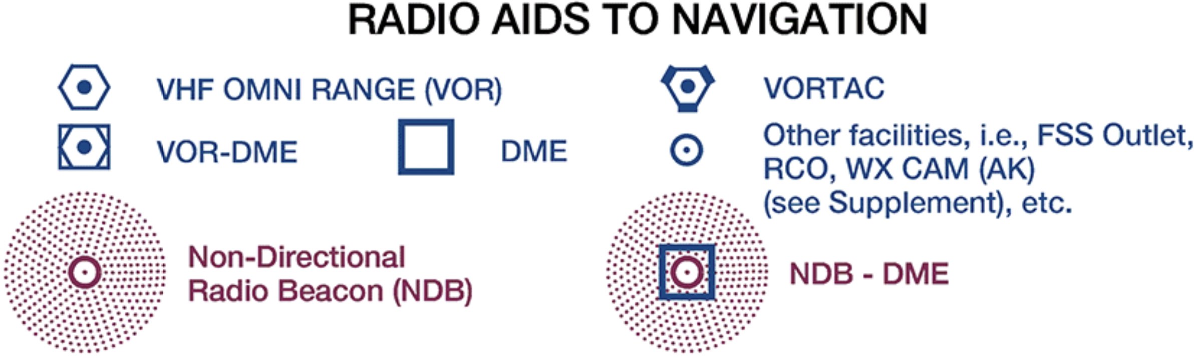
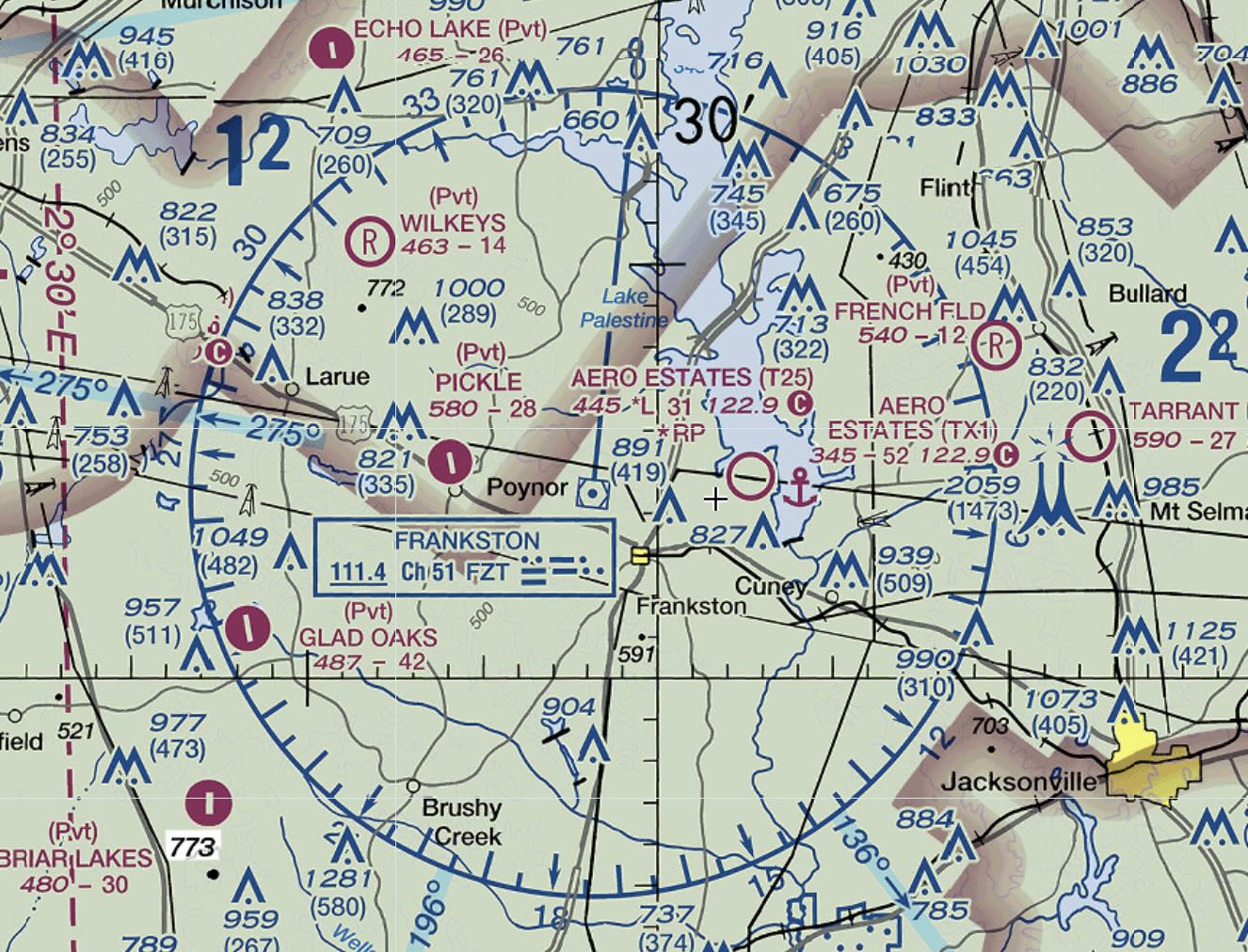
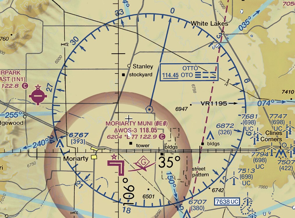
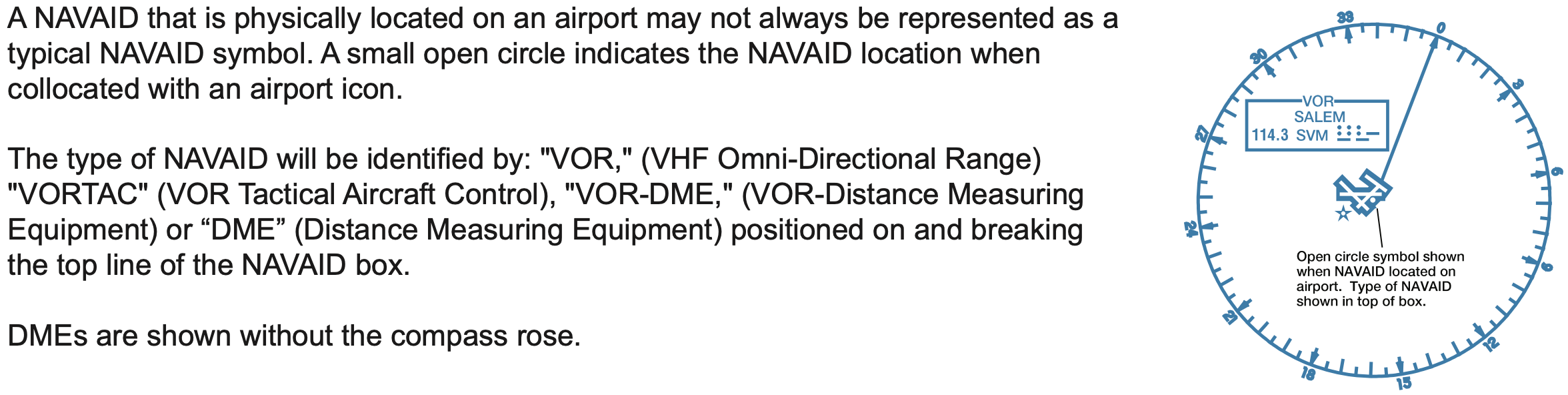
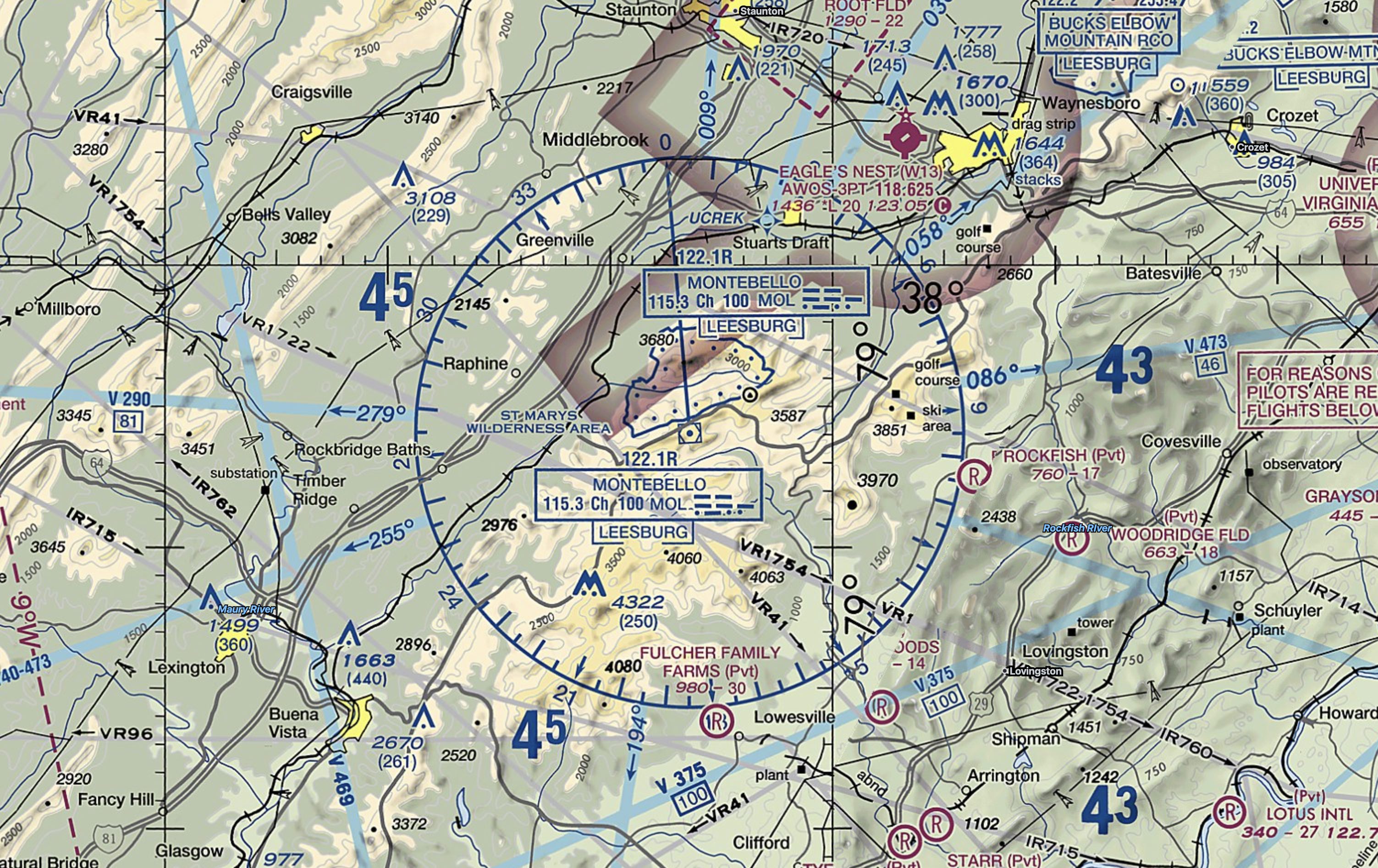
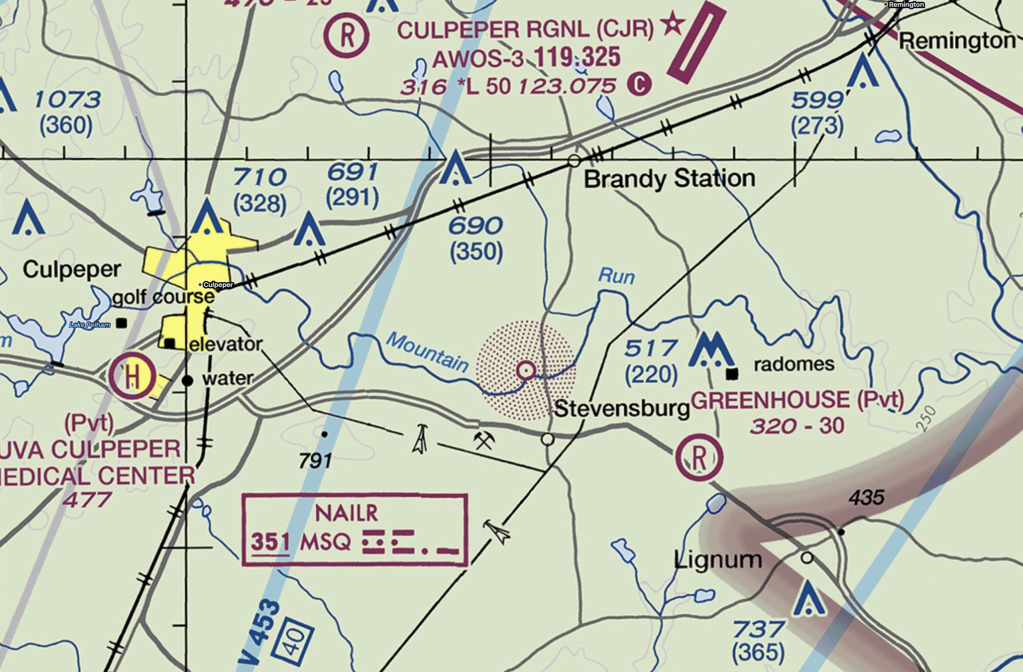
VOR Symbols on Charts
- There are several different types of VOR facilities, each of which slightly different capabilities.
- These facilities are described more in detail below.
- For now, note each different type of VOR facility is charted slightly differently on aeronautical charts.
- The screenshots below are from VFR sectionals, but the same symbols are used on IFR charts.
- The most common type of VOR facility is the VORTAC, then the VOR/DME, with VOR being fairly uncommon.

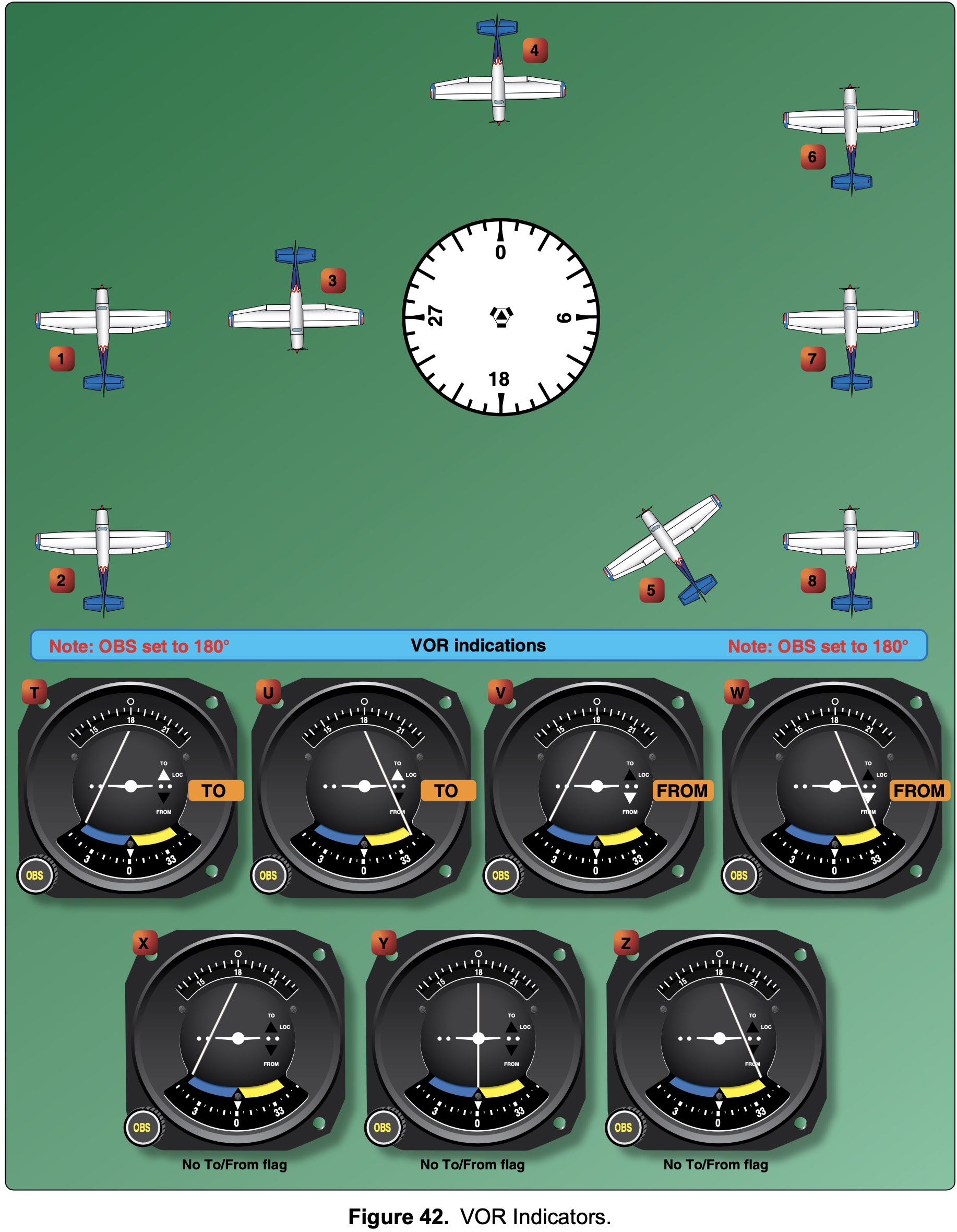
VOR Indicator
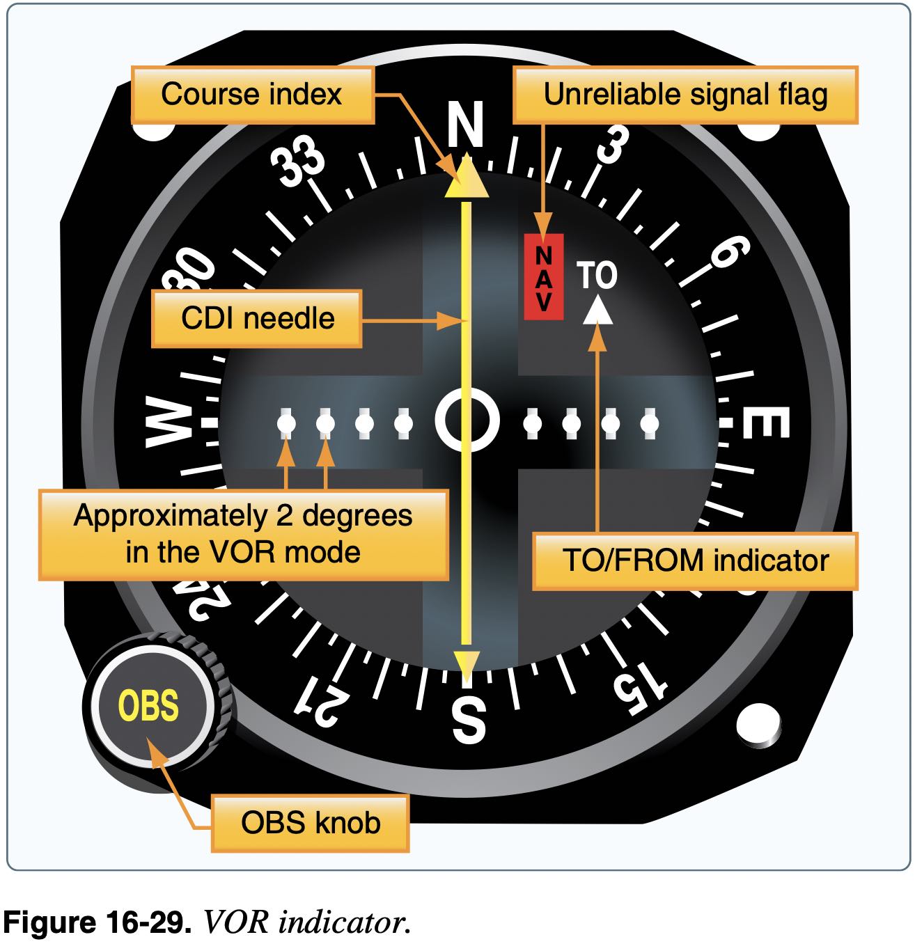
- The VOR indicator also provides information with the Course Deviation Indicator (CDI)
- This gives the pilot information as to how far off course they are when they have selected a radial by way of a needle that deflects left or right from center
- Full-scale deflection on VOR is a deviation of 10 to 12 degrees.
- Each 1 nm from the VOR, two adjacent radials are 100 ft further apart
- So 60 nm from the VOR two adjacent radials would be 6000 ft apart or about 1 nm
- Or if 30 nm from station and 2 degree deflection on needle, are 6000 ft off course, or about 1 nm off course.
- Make sure the selected VOR is correct and functional before using
- Check the morse code audio
- Ensure the avionics displays the VOR identifier
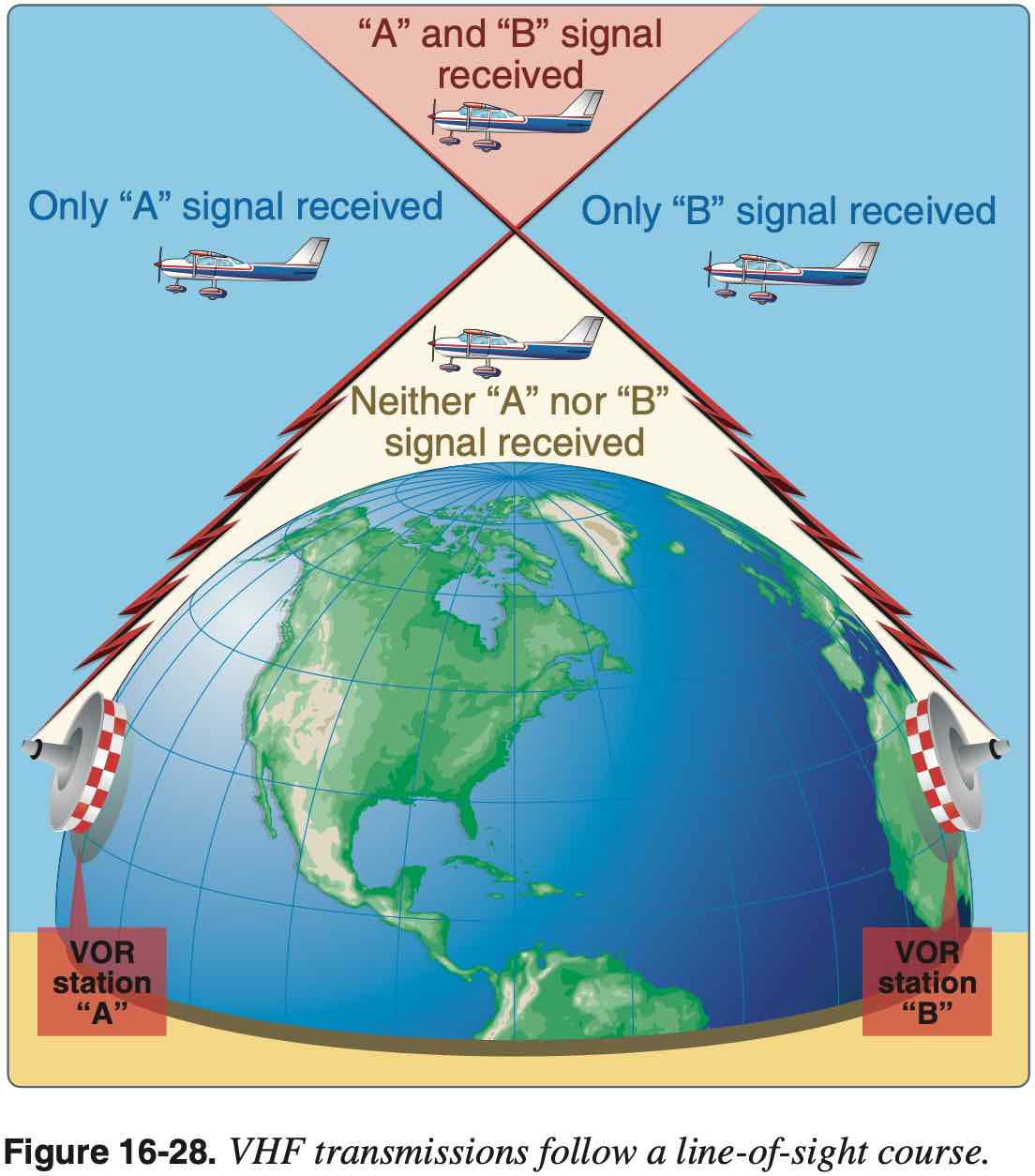
- VOR is line-of-sight transmission
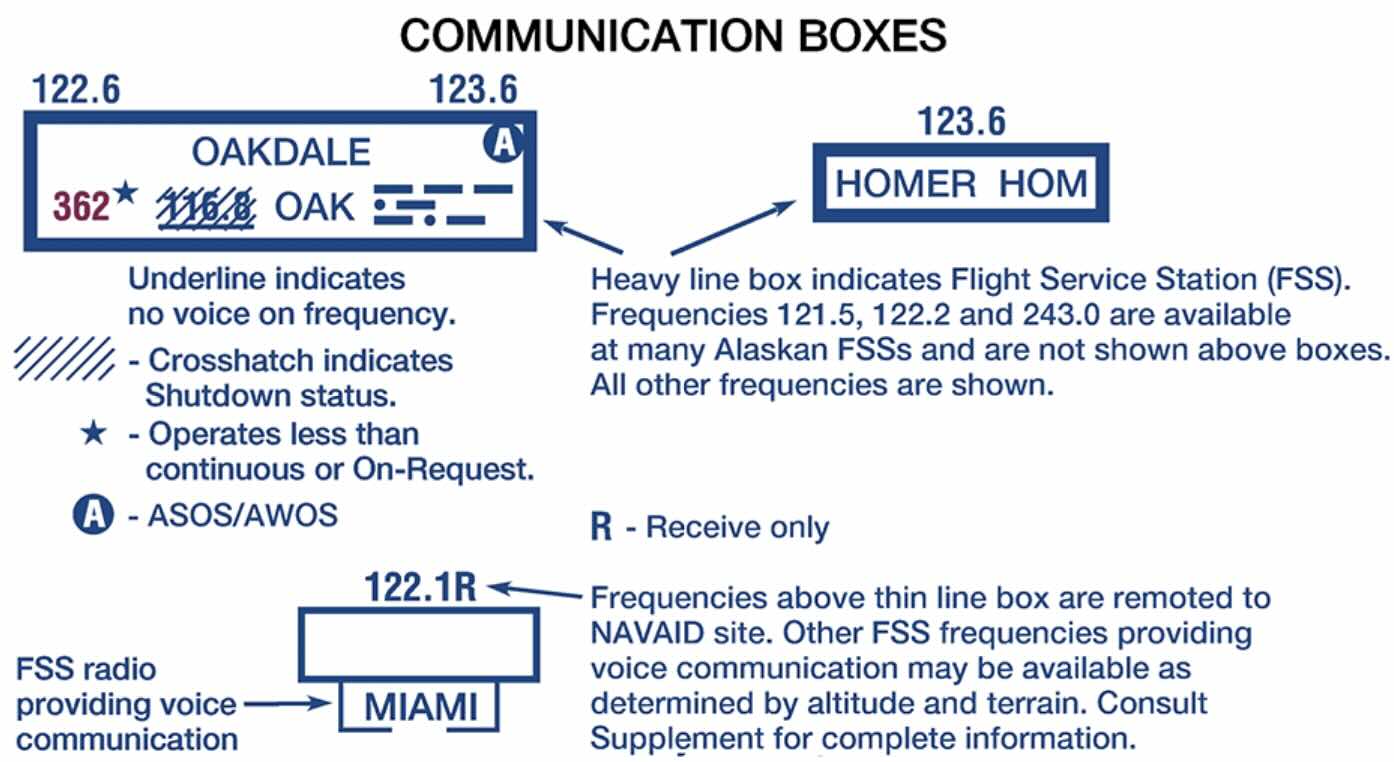
Voice Capabilities
- VORW is a VOR without voice
- VORW are denoted on charts by underlining the VOR frequency
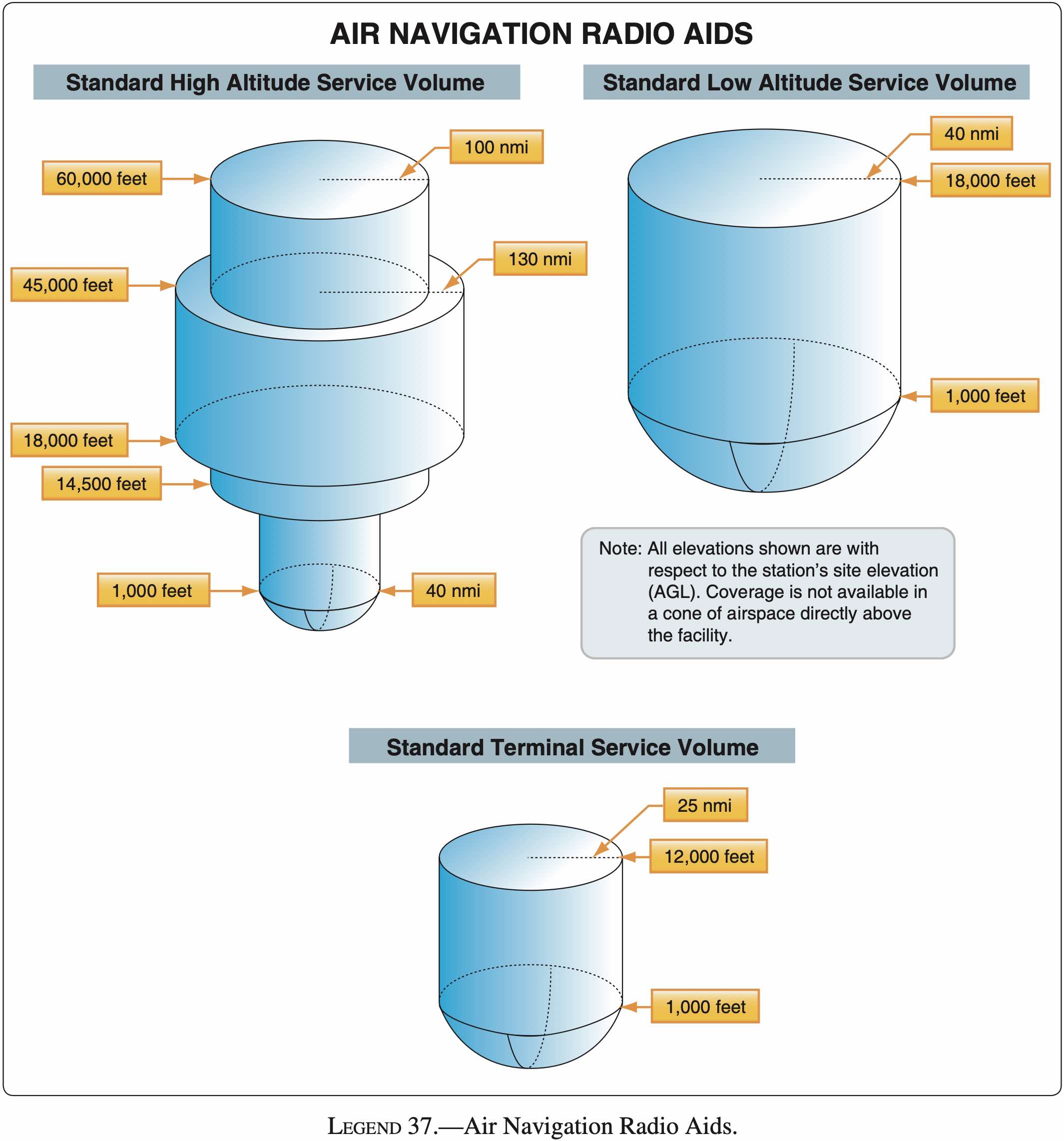
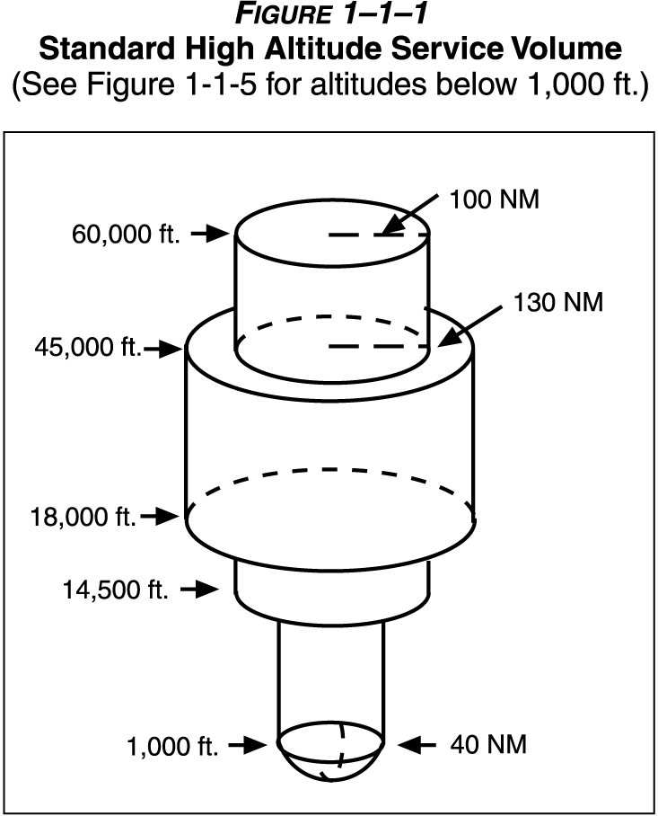
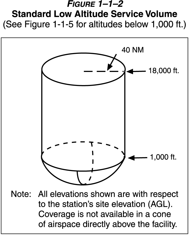
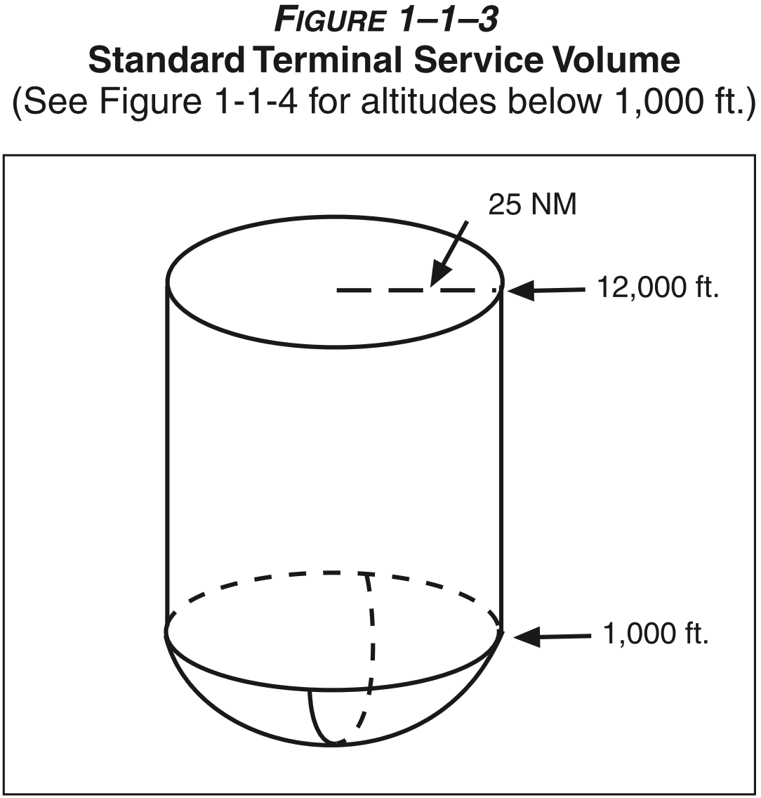
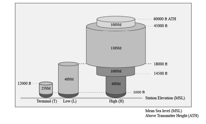
Legacy Service Volumes
- Three classes of legacy VOR / VORTAC that define service volume:
- T (Terminal)
- L (Low altitude)
- H (High altitude)
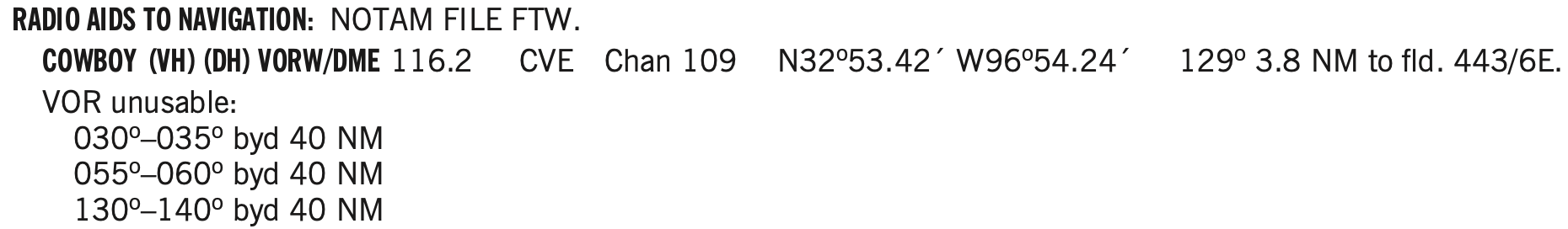
1-1-8. NAVAID SERVICE VOLUMES
a. Most air navigation radio aids which provide positive course guidance have a designated standard service volume (SSV).
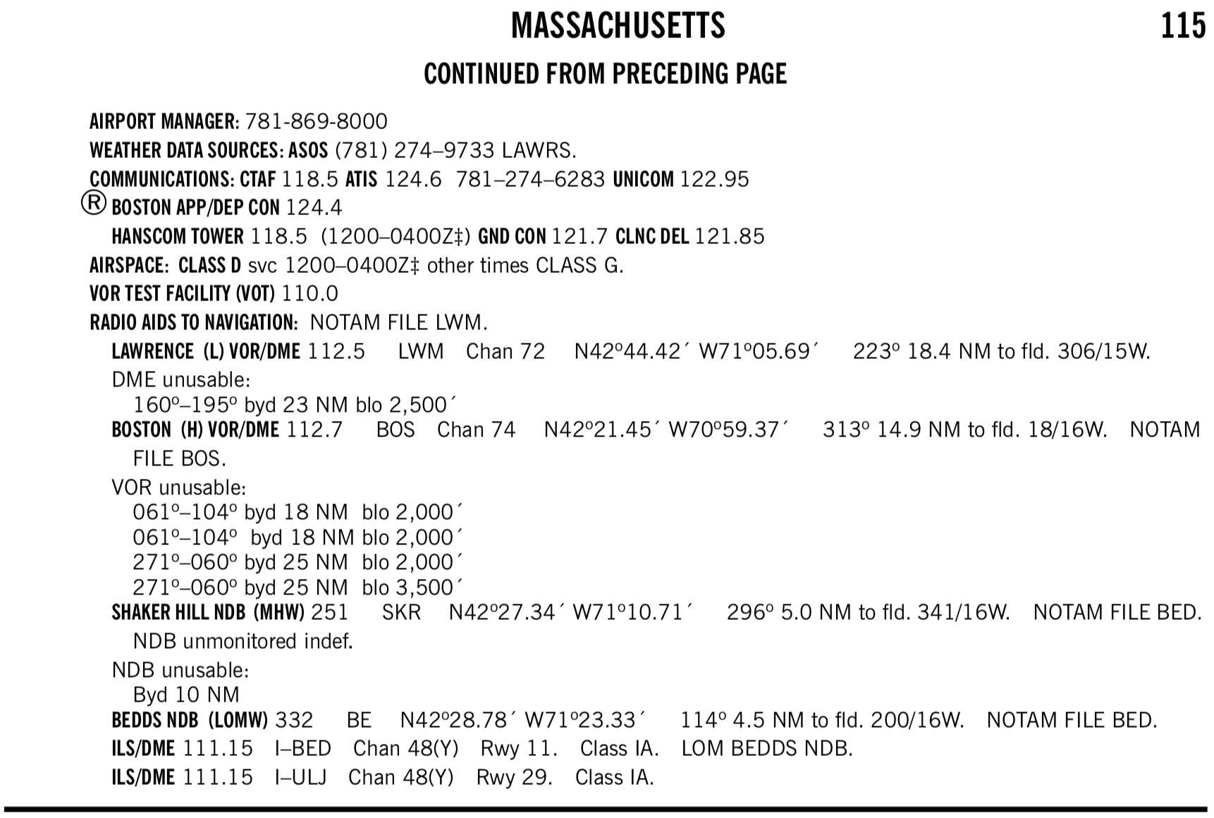
- To find the service volume class of a given VOR
- Can find the service volume in the Chart Supplement.
- For example see
BOSTON (H) VOR/DMEindicating it is a high class(H)
- For example see
- See also: Aviation StackExchange How do you know if a VOR is High, Low, or Terminal?
- Can also check low and high altitude IFR charts to see which appear on each.
- Here it is implicit, but Low Class
(L)VORs will not appear on the IFR High Chart as their service volume tops out at 18,000 ft. AGL, and IFR charts are for use at or above 18,000 ft. MSL. - Note the difference between AGL and MSL. I don't know at what altitude the IFR high charts top out at, but there are Maximum Authorized Altitudes (MAA) so conceivably a Low Class
(L)VOR located at 10,000 ft. MSL, for example, would provide 40 nm radius of service up to 28,000 ft. MSL and be used on a high chart. - In any case, following what is on the IFR charts for VOR navigation ensures a pilot need not worry too much about the various service volumes.
- Here it is implicit, but Low Class
- Can find the service volume in the Chart Supplement.
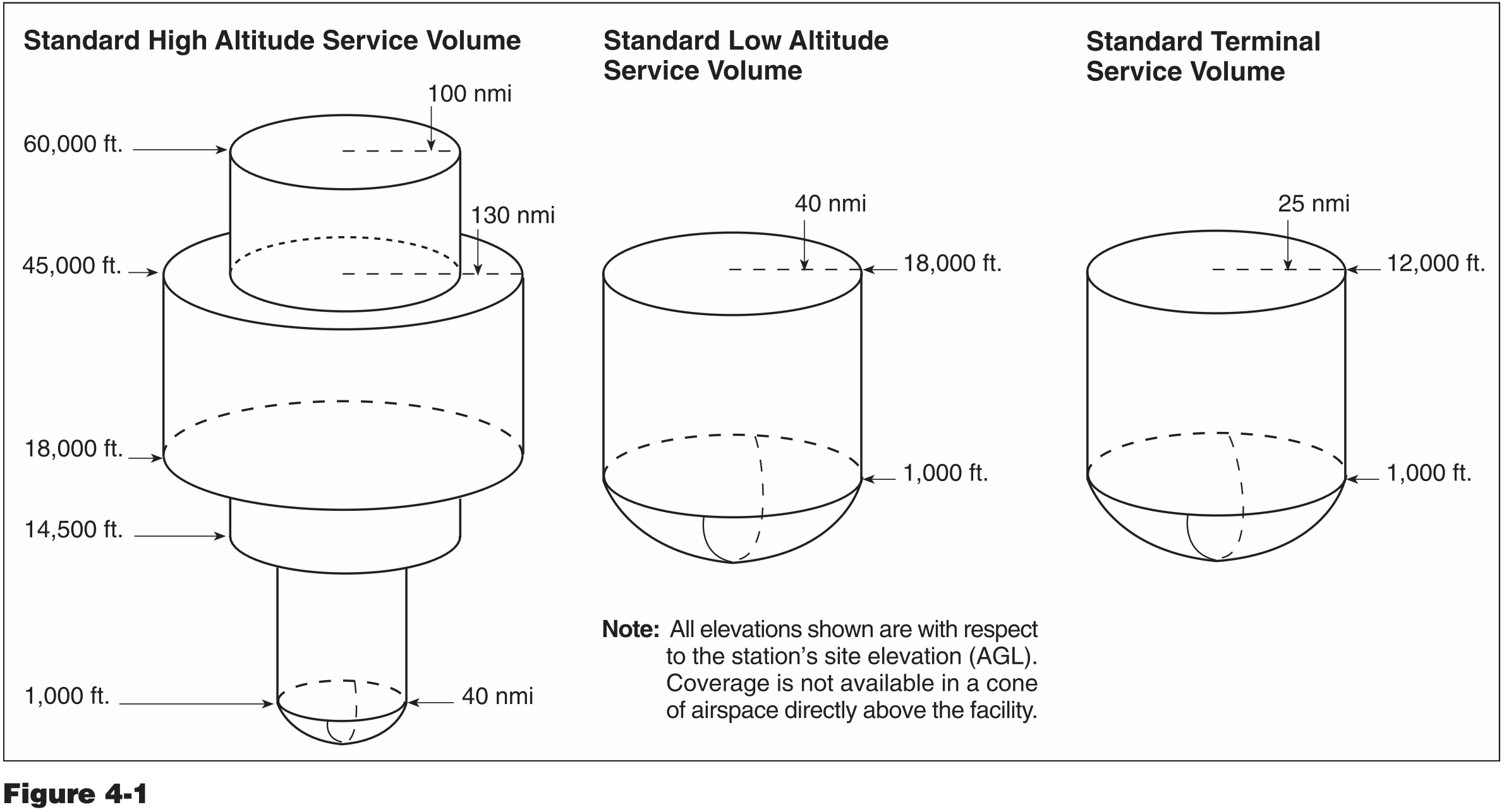
New Service Volumes
- Insert picture here
TACAN, VORTAC, and VOR/DME
- VOR is present in three different navigational aids
- VOR
- This is the fundamental capability described above
- VOR/DME
- When distance measuring equipment (DME) is installed with the VOR, tuning the VOR VHF frequency automatically selects the corresponding UHF DME frequency
- DME is affected by slant-range errors, worse when closer to station and higher altitudes
- AIM 1-1-7 Distance Measuring Equipment (DME)
- VORTAC
- Combination of VOR and TACAN, where TACAN is military equipment, but provides DME to civilian users
- Provides three pieces of information
- VHF azimuth information
- UHF TACAN azimuth information (like azimuth provided by VOR but for military only)
- UHF TACAN distance information (can be used by non-military)
- If VORTAC undergoing maintenance will not hear the morse code identifier
- DME and VOR morse codes are transmitted seperately (even though they are the same identifier)
- DME identifier is transmitted once for each 3-4 times the VOR identifier is transmitted
- So depending on what is heard when listening for the identifier you can tell whether the DME is out or the VOR or both
- DME is affected by slant-range errors, worse when closer to station
- TACAN technology is very different from civilian DME, but the pilot's interaction with each is the same
- AIM 1-1-5 Tactical Air Navigation (TACAN)
- AIM 1-1-6 VHF Omni-directional Range/Tactical Air Navigation (VORTAC)
- VOR
- VHF radio band is 30 to 300 MHz
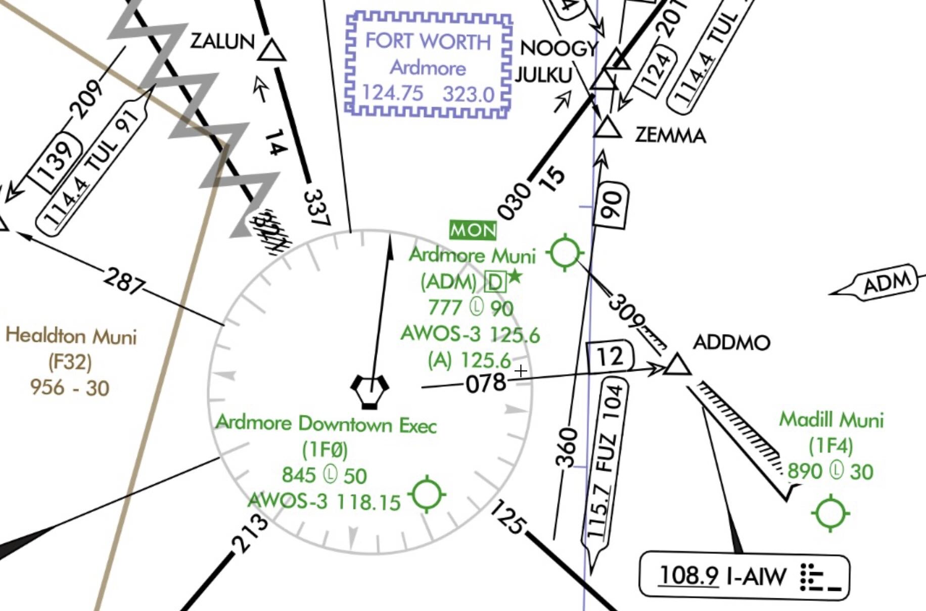
VOR MON
As VORs are gradually being phased out in favor of GPS, a limited network of VORs will be kept which will make up the VOR MON network, and enable some level of navigation using this system in the event that GPS is unavailable.
Certain airports are also designated MON airports.
According to the Aeronautical Chart User Guide Complete:
MON Airports with the Airport designator at the top of the Airport Data Block. The MON designation is to alert pilots to those airports that have retained ILS and VOR instrument approach procedures for safe recovery in the event of a GPS outage. Refer to the Aeronautical Information Manual (AIM) for expanded MON Airport guidance.
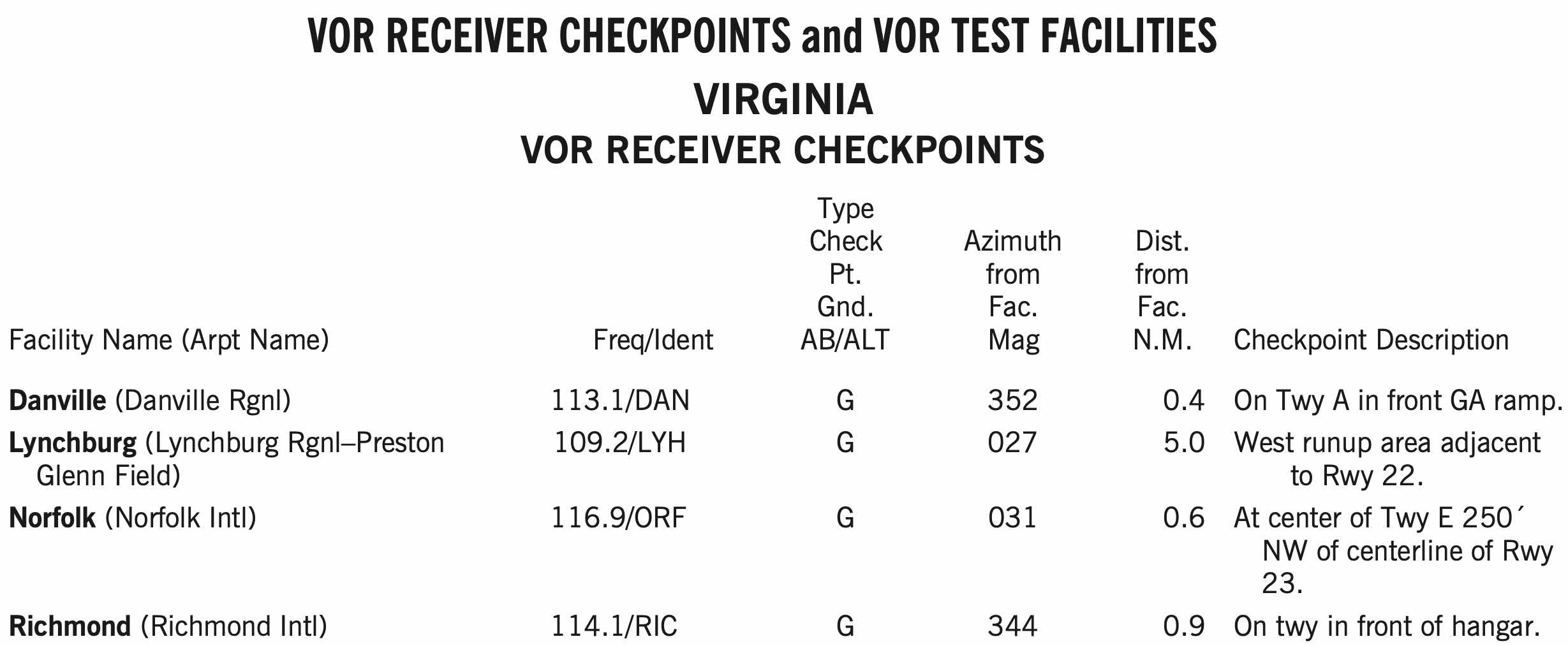
VOR Check
- Recall from AVIATE acronym, VOR needs to be checked every 30 days for IFR
- VOR accuracy requirements 14 CFR §91.171(b), (c)
- VOT: +/- 4 deg
- Can be checked on the ground or in the air, as indicated in the chart supplement for that facility
- Ground checkpoint: +/- 4 deg
- Airborne checkpoint: +/- 6 deg
- Dual check: within 4 deg
- VOT: +/- 4 deg
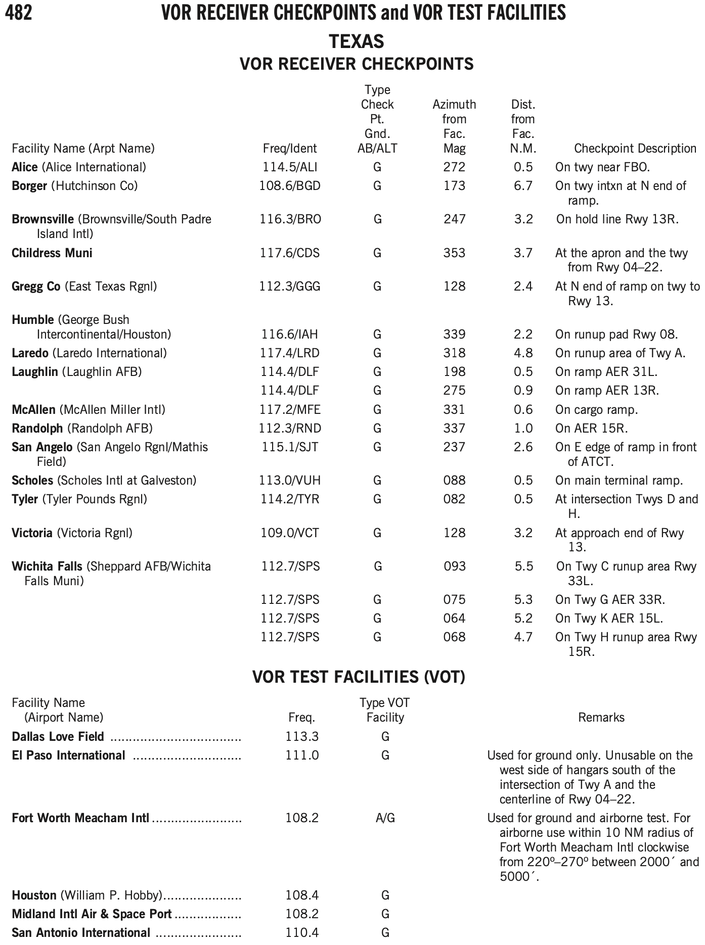
- Can find VOT facilities and VOR checkpoints in the chart supplement.
- Log the results of the VOR accuracy test in the aircraft logbook or other record including the PADS acronym:
- P - Place
- A - Accuracy (bearing error)
- D - Date
- S - Signature
- VOT is the most convenient way to perform a VOR check if your home airport happens to have one
- Similarly, ground checkpoints are also a convenient option
VOR Ground Checkpoint
- Has a sign in front of the arrow with the radial and frequency

VOT Check
- A VOT is a facility located at certain airports that emits a signal that can be used to test a plane's VOR receiver
- The VOT signals are generally designed to be used while on the ground, but some are designated as usable in air, with certain restrictions
- This information can be found in the chart supplement
- Dial a course of 180° in using the OBS, should see the needle center (within +/- 4 degrees) with a
TOindication.
Nondirectional Radio Beacon (NDB) / Automatic Direction Finder (ADF)
- FAA-H-8083-15B Instrument Flying Handbook
- Chapter 9: Navigation Systems
- Page 9-3: Nondirectional Radio Beacon (NDB)
- Chapter 9: Navigation Systems
- AIM 1-1-2 Nondirectional Radio Beacon (NDB)
- A low or medium frequency radio beacon transmits nondirectional signals whereby the pilot of an aircraft properly equipped can determine bearings and "home" on the station
- These facilities normally operate in a frequency band of 190 to 535 kilohertz (kHz)
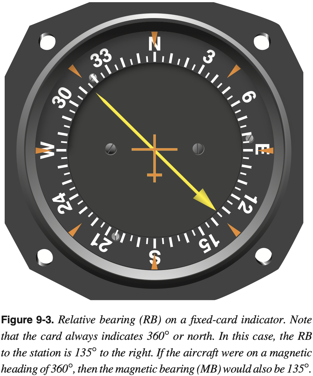
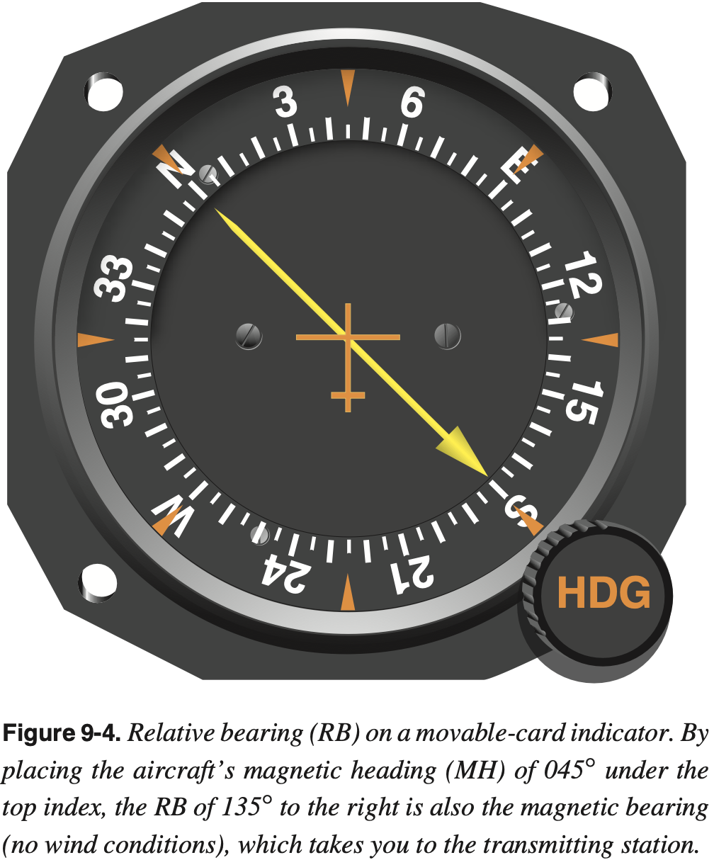
- Information from an NDB is displayed to the pilot on an Automatic Direction Finder (ADF) of which there are four kinds
- Fixed-card ADF also known as the relative bearing indicator (RBI)
- Rotatable compass-card ADF
- Radio magnetic indicator (RMI) (with either one needle or dual needle)
- All radio beacons, except compass locators, transmit a continuous three-letter identification in code, except during voice transmissions
- NDBs have one advantage over the VOR in that low or medium frequencies are not affected by line-of-sight
- If the aircraft is within the range of the station, the signals can be received regardless of altitude
- One of the disadvantages that should be considered when using low frequency (LF) for navigation is that LF signals are very susceptible to electrical disturbances, such as lightning.
- The ADF needle points TO the station, regardless of aircraft heading or position.
- Navigating to an NDB
- Homing
- Tracking
Using Ground-based Navaids in Flight
- VOR Indicator
- Described above
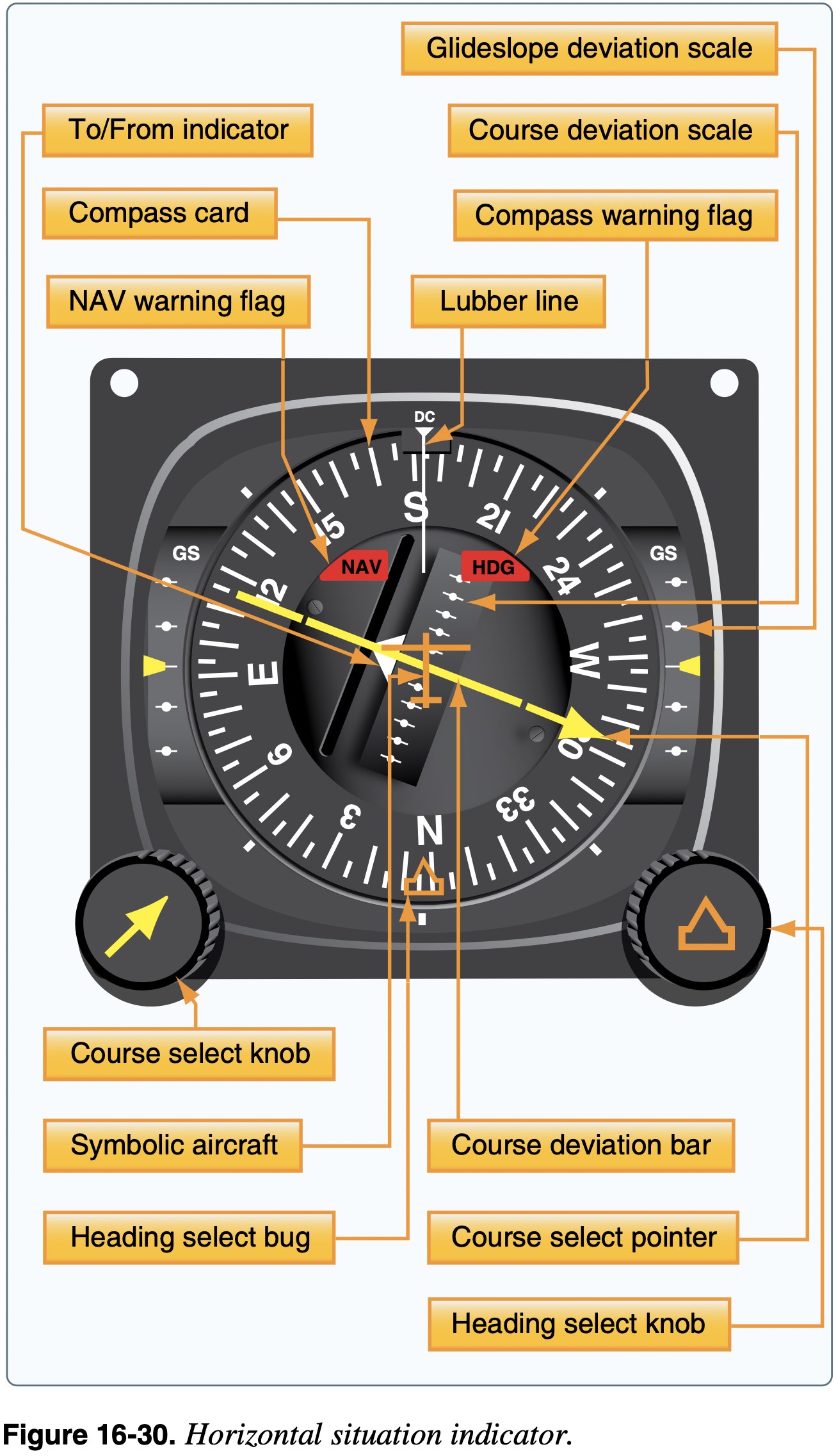
- Horizontal Situation Indicator (HSI)
- Combines the magnetic compass with navigation signals and a glideslope
- The HSI gives the pilot an indication of the location of the aircraft in relation to the chosen course or radial
- The desired course is selected by rotating the course select knob, which moves the course select pointer
Satellite Based Navigation
Overview
Global Navigation Satellite System (GNSS)
The generic term for satellite based navigation systems used around the world.
- As the title implies, satellite based navigation uses signals from satellites to determine location.
- These satellites are placed in a medium-Earth orbit.
- There are four constellations of such satellites operated by various bodies around the world:
- GPS - United States
- GLONASS - Russia
- Galileo - EU
- BeiDou (BDS) - China
Global Positioning System (GPS)
The particular GNSS system used in the United States.
- Given GPS is the system used in the United States, this document will refer to GPS, but much of what applies to GPS applies to the other GNSS systems as well.
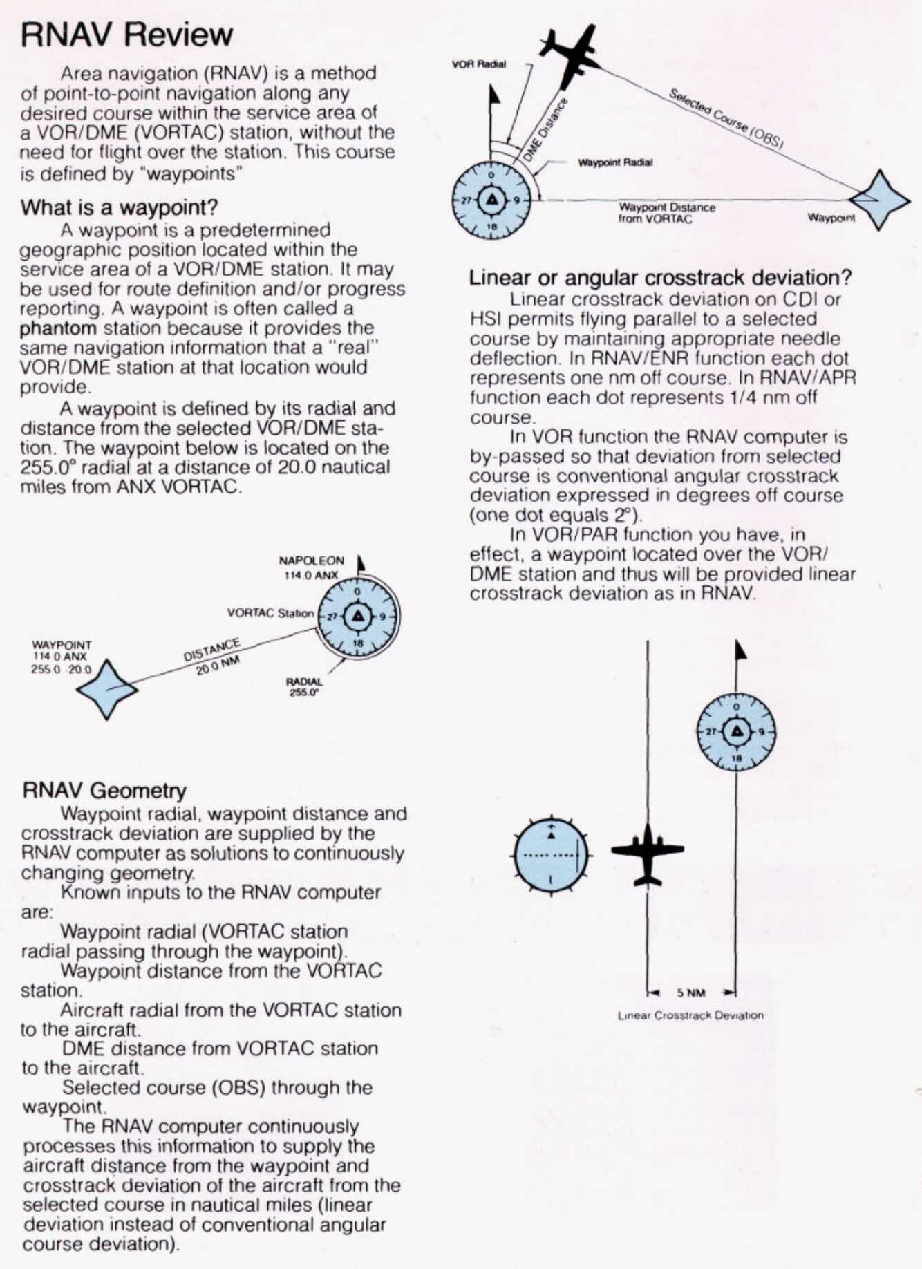
A History of Area Navigation (RNAV)
A method of navigation that permits aircraft operations on any desired flight path.
- GPS systems provide a capability called Area Navigation (RNAV) which, unlike using a traditional VOR receiver which only allows flying toward or away from the ground station, allows the navigation between arbitrary points.
- As GPS is overwhelmingly the means by which modern RNAV is possible these terms are often conflated.
- It is important to remember that they are distinct concepts, and while GPS can provide RNAV capability, RNAV systems did exist prior to GPS.
- Methods of area navigation that predate GPS include
- Visual reference (e.g. stars)
- Inertial Navigation Systems (INS)
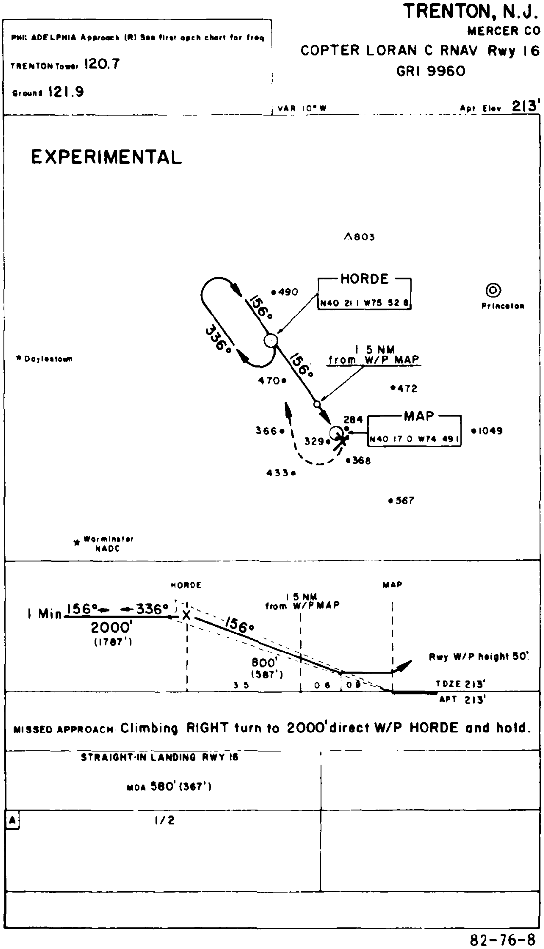
- LORAN C
- See FAA-AC-90-92
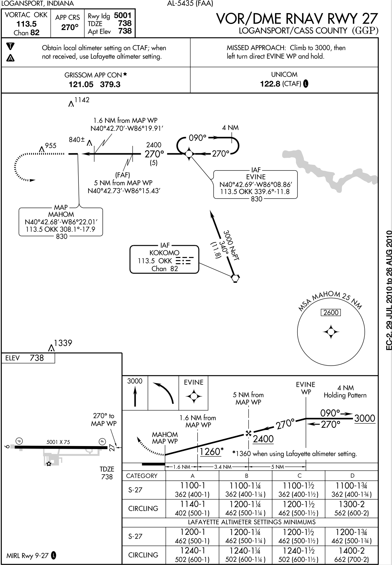
- VOR/DME
- DME/DME
- See FIU RNAV
- Some such VOR based RNAV recievers include
- The Bendix/King KNS 80 Digital Area Navigation System is an RNAV receiver based on VOR
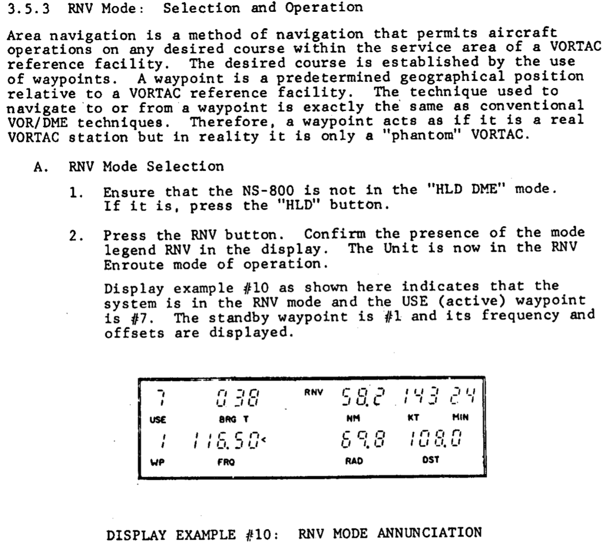
- Narco NS-800
- King KN-74
- They enabled flight between waypoints that were defined by VORs, but without having to fly along the radials of VORs
- FAA-AC-90-45A Approval of Area Navigation Systems for use in the US National Airspace System from 1975 describes guidelines for RNAV systems, well before the existence of GPS
- With a little bit of background on legacy RNAV systems, we can now focus on GPS.
GPS Satellites
- The GPS constellation currently consists of 31 operational satellites
- GPS is designed so that as long as 24 GPS satellites are working, at least 5 should be visible at any time
- AIM 1-1-17(a)(3)(a)
- Need 4 satellites to have GPS
- This gives latitude, longitude, altitude, and time
- Need 5 satellites for RAIM
- More on RAIM below
- Need 6 satellites to remove corrupt GPS signal
- Need 4 satellites to have GPS
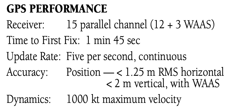
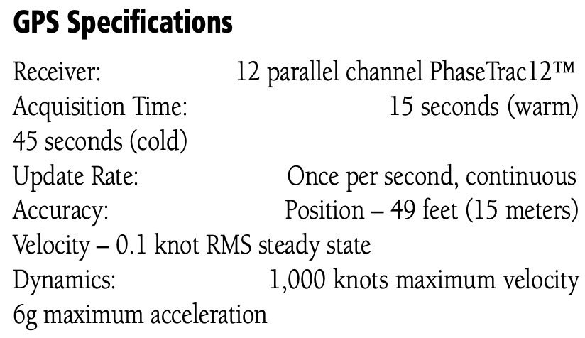
GPS Receiver
- A typical GPS receiver has at least 12 channels
GPS Database
- GPS databases are updated every 28 days
- Usually every 4th Thursday of the month
- Pilots can update GPS database if they can do it from instrument panel without special tools or disassembly of the unit
- Take the SD card out and update it
Performance Based Navigation (PBN)
Performance Based Navigation (PBN) is comprised of Area Navigation (RNAV) and Required Navigation Performance (RNP) and describes an aircraft's capability to navigate using performance standards.
AIM 1-2-1 says:
PBN exists under the umbrella of area navigation (RNAV). The term RNAV in this context, as in procedure titles, just means “area navigation,” regardless of the equipment capability of the aircraft.
This can be confusing given the difference between RNAV as a concept (area navigation) and RNAV as a navigation specification similar to RNP.
PBN defines a set of standards and doesn't depend on a particular technology.
Therefore, procedures can be defined that depend on these standards and can be used without being changed as new technology is developed.
RTCA DO-229 defines these standards.
These standards, refered to as NavSpecs apply to both aircraft and aircrew.
It also doesn't help that ICAO and the FAA differ somewhat in their use of terminology.
For an aircraft to meet the requirements of PBN, a specified RNAV or RNP accuracy must be met 95 percent of the flight time.
NavSpecs should be considered different from one another, not “better” or “worse” based on the described lateral navigation accuracy.
As a safeguard, the FAA requires that aircraft navigation databases hold only those procedures that the aircraft maintains eligibility for. If you look for a specific instrument procedure in your aircraft's navigation database and cannot find it, it's likely that procedure contains PBN elements your aircraft is ineligible for or cannot compute and fly. Further, optional capabilities such as Radius-to-fix (RF) turns or scalability should be described in the AFM or avionics documents. Use the capabilities of your avionics suite to verify the appropriate waypoint and track data after loading the procedure from your database.
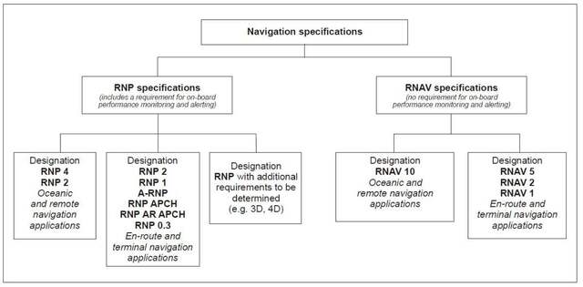
Required Navigation Performance (RNP)
- RNP is a navigation specification under Performance Based Navigation (PBN)
- Three standard RNP levels, where the value is nautical miles each side of centerline that must be maintained for aircraft and obstacle clearance
- RNP 0.3 – Approach
- RNP 1.0 – Departure, Terminal
- RNP 2.0 – En route
- The performance requirements of PBN are conveyed to the operators through navigation specifications, or NavSpecs.
- The values listed above are the lateral limits, in nautical miles, of the errors within which the system must remain 95% of the time
NOTE
RNP Requires
- A specified accuracy be met 95% of the time
- Onboard performance monitoring and alerting
RNAV Navigation Specification
- AIM 1-2-1(a)
- The term RNAV X means a specific navigation specification with a specified lateral accuracy value.
- No requirement for onboard performance monitoring and alerting.
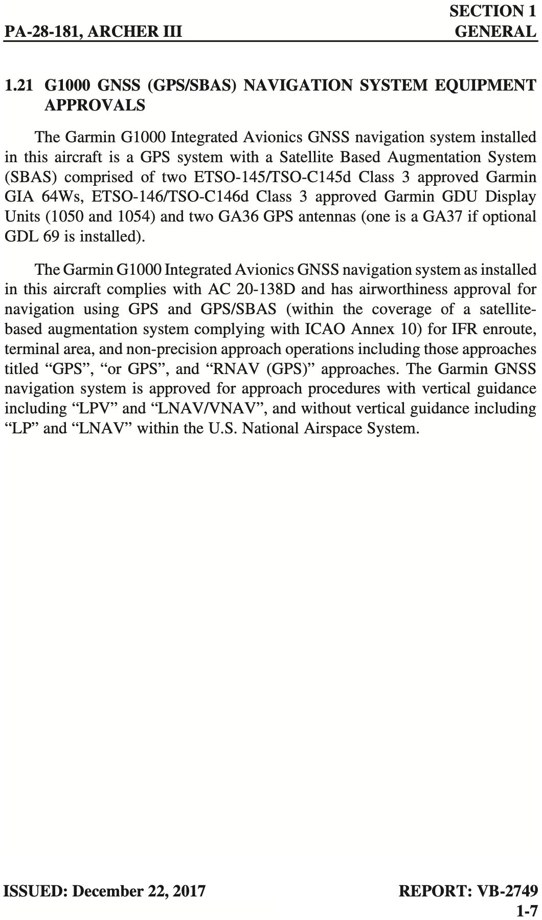
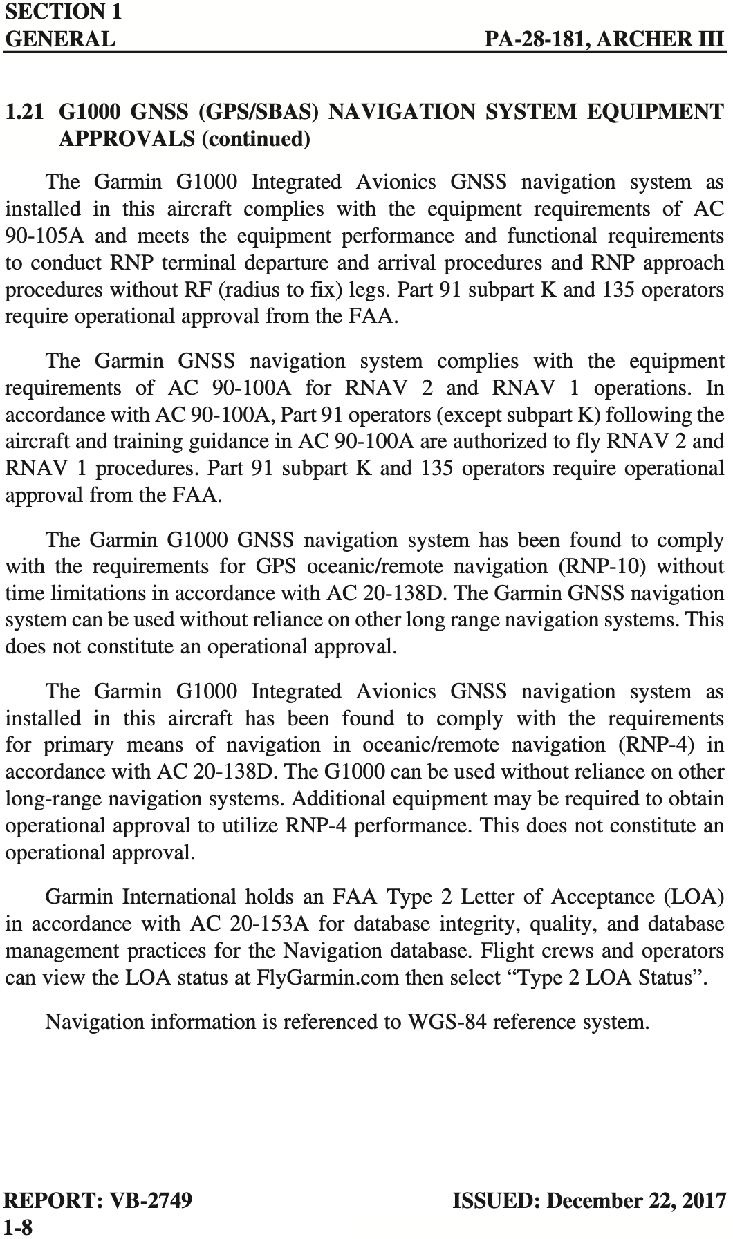
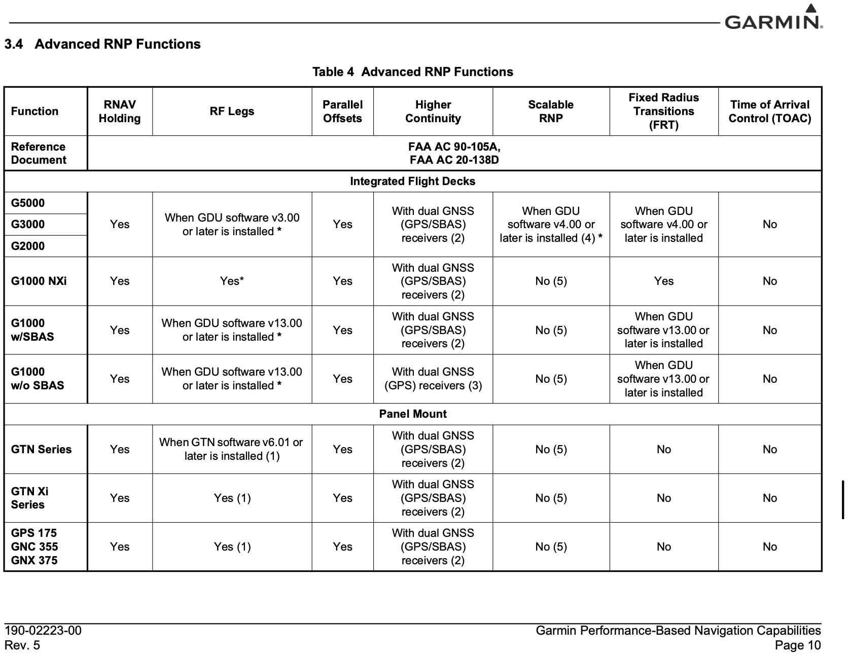
Aircraft Equipment Requirements
- The Piper Archer III NXi G1000 system satisfies the following requirements:
- RNP APCH (without RF)
- RNP 1 (terminal operations)
- RNAV 1 and RNAV 2
- RNP-10 (oceanic and remote continental operations)
- Determining what requirements a particular aircraft satisfies can be challenging.
- The excerpt from Garmin Performance-Based Navigation Capabilities document indicates some RNP functions for various products
- Some capabilities depend on software versions, so be sure to check carefully what RNP capabilities an aicraft has before flying
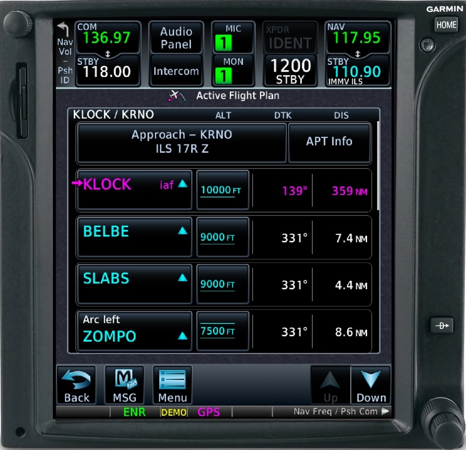
- The Garmin GTN750, which can support RF legs, are indicated in the flight plan view as shown below
RNP AR APCH (AR for Authorization Required)
General aviation operations do not have the authorization required to fly these approaches
In the U.S., RNP AR APCH procedures are titled RNAV (RNP). These approaches have stringent equipage and pilot training standards and require special FAA authorization to fly. Scalability and RF turn capabilities are mandatory in RNP AR APCH eligibility.
Relevant Advisory Circulars
- FAA-AC-91-105A for RNP definitions
- FAA-AC-91-100A for RNAV definitions
- FAA-AC-91-107 for LP and LPV approaches
- FAA-AC-90-101A for RNP procedures with AR
- FAA-AC-20-138D for airworthiness approval
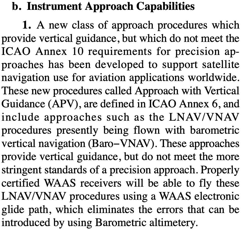
In the past, LNAV/VNAV required a baro-aided altimeter
This has changed to allow appropriately certified WAAS GPS systems to fly LNAV/VNAV approaches, but I don't know exactly when this happened
- One data point is in the 2012 version of the AIM, which states that properly certified WAAS received will be able to fly LNAV/VNAV approaches
- Earlier references indicate the ability to use an appropriate WAAS GPS for LNAV/VNAV approaches
- WAAS was authorized for IFR use in 2003, so certainly before that LNAV/VNAV approaches would have required a baro-aided altimeter
- FAA-AC-90-97 (which was canceled by FAA-AC-91-105A) describes the use of barometric vertical guidance for VNAV

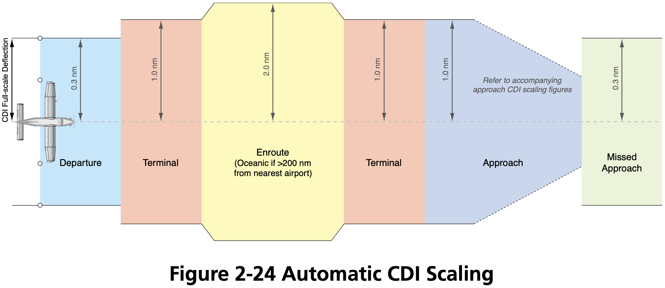
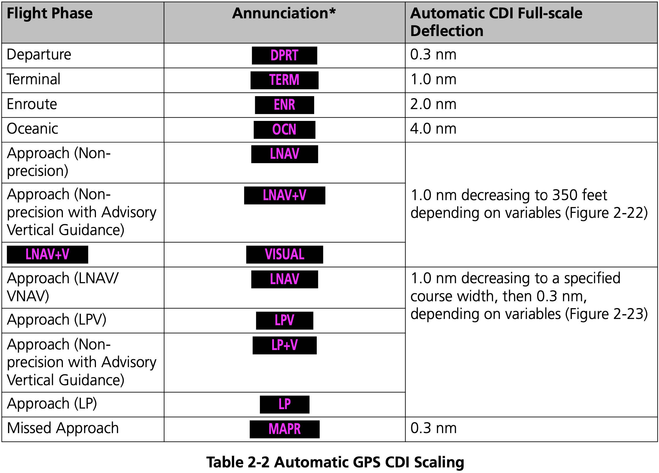
GPS Sensitivity Modes
- Three GPS modes
- Enroute
- More than 30 miles from departure/destination
- 2 nm full-scale deflection
- Terminal
- Within 30 nm of departure/destination
- 1 nm full-scale deflection
- Approach
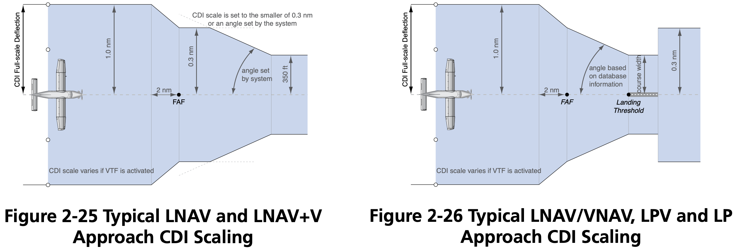
- 2 nm before final approach waypoint (FAWP) aka final approach fix (FAF)
- 0.3 nm full-scale deflection
- This approximates the sensitivity of a VOR or Localizer approach if located on the field
- Enroute
GPS Routes
- See AIM 5-3-4
- Q Routes: from 1,200 up to but not including 18,000' MSL
- T Routes: from 18,000 up to FL450
- GPS MEA, e.g.
2900G - Airway width is 4 nm on each side of centerline
- Jet routes
- Start with letter J
- From 18,000 up to FL450
- Have no specified width
Regulations
- Technical Standard Orders (TSO) are the regulations that describe GNSS certification
- Three primary categories
- TSO-C129 / TSO-C196
- Non-WAAS GPS systems
- TSO-C196 seems to be an improved version of TSO-C129
- TSO−C145 / TSO−C146
- WAAS GPS systems
- Uncertified
- VFR-only GPS for advisory / situational awareness
- See AIM Table 1-1-6
- May be used for reference
- May not be used for navigation or approaches
- TSO-C129 / TSO-C196
- Check the AFM or AFM supplement that accompanies the GPS installation that will state whether it is approved for IFR, and under what regulations.
- FAA-AC-20-138D
- Describes certification of GPS
- FAA-AC-20-138D

Non-WAAS GPS
Also called non-augmented GPS
May be used as primary source of navigation if the aircraft has working conventional navigation equipment (e.g. VOR receiver)
Use of a suitable RNAV system as an Alternate Means of Navigation when a VOR, DME, VORTAC, VOR/DME, TACAN, NDB, or compass locator facility including locator outer marker and locator middle marker is operational and the respective aircraft is equipped with operational navigation equipment that is compatible with conventional navaids. For example, if equipped with a suitable RNAV system, a pilot may fly a procedure or route based on operational VOR using that RNAV system without monitoring the VOR.
However, RAIM must be available and working to use GPS as a primary source of navigation
Operators planning to use TSO-C129 equipment as a substitute means of navigation must perform a RAIM prediction during preflight. GPS RAIM availability must be confirmed for the applicable operation and time using current GPS satellite information.
For all RNAV systems, substitute and alternate means of navigation must be discontinued upon loss of integrity (for example, RAIM alert) or unacceptable degradation of system performance.
GPS can be used in lieu of VOR/DME/ADF etc.
- FAA-AC-90-108
- Stated exception is substituting for lateral guidance on final approach course which is discussed in AIM 1-2-3(c) Note 5
- This includes over 24,000 feet requirement to have DME
- FAA-AC-90-108
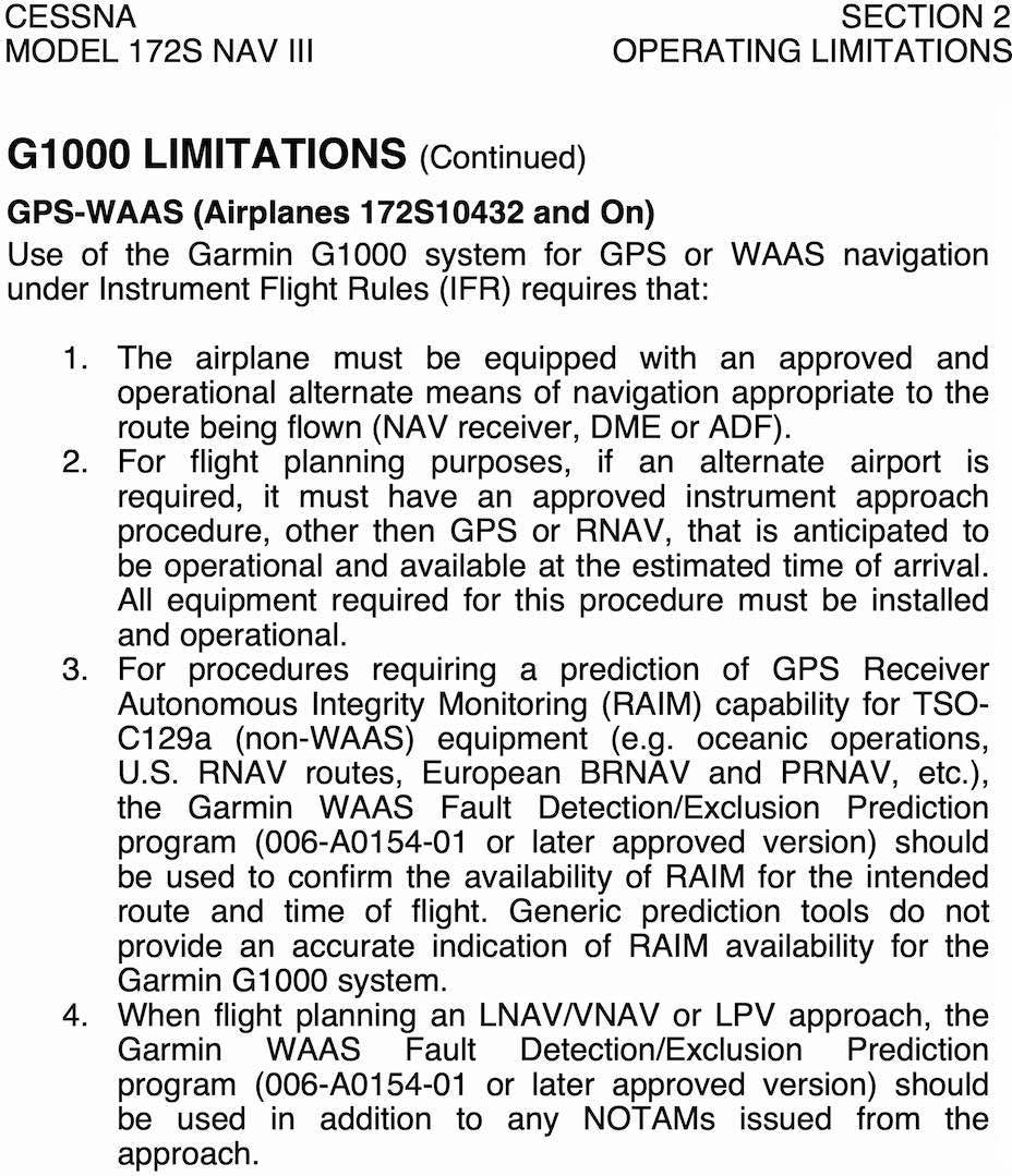
When selecting an alternate airport for an IFR flight plan, the alternate must have a non-GPS approach that the aircraft is equipped to fly.
For the purposes of flight planning, any required alternate airport must have an available instrument approach procedure that does not require the use of GPS.
This restriction does not apply to RNAV systems using TSO-C145/-C146 WAAS equipment.
However, if the GPS unit has RAIM, and a RAIM check is performed, then an alternate with only a GPS approach can be used, but only if the destination has an approach other than GPS that the aircraft is equipped to fly.
For flight planning purposes, TSO-C129() and TSO-C196() equipped users (GPS users) ... may file based on a GPS-based IAP at either the destination or the alternate airport, but not at both locations.
TIP
Basically, if you are using a non-WAAS GPS, you must make sure RAIM is available and working before using the GPS under IFR.
Receiver autonomous integrity monitoring (RAIM)
RAIM
Receiver autonomous integrity monitoring (RAIM) is a technology for a GPS unit to assess the integrity of GPS signals it receives to make sure they are correct. AIM 1-1-17(a)(3)
RAIM requires a minimum of 5 satellites, or 4 satellites and barometric altimeter input (baro-aiding), to detect an integrity anomaly. Baro-aiding is a method of augmenting the GPS integrity solution by using a non-satellite input source in lieu of the fifth satellite. Some GPS receivers also have a RAIM capability, called fault detection and exclusion (FDE), that excludes a failed satellite from the position solution; GPS receivers capable of FDE require 6 satellites or 5 satellites with baro-aiding.
See also FAA-AC-90-100A U.S Terminal and En Route Area Navigation (RNAV) Operations
Regarding RAIM failure during a GPS approach AIM 1-1-17(b)(5)(g)(6):
If a RAIM failure/status annunciation occurs prior to the final approach waypoint (FAWP), the approach should not be completed since GPS no longer provides the required integrity. The receiver performs a RAIM prediction by 2 NM prior to the FAWP to ensure that RAIM is available as a condition for entering the approach mode. The pilot should ensure the receiver has sequenced from “Armed” to “Approach” prior to the FAWP (normally occurs 2 NM prior). Failure to sequence may be an indication of the detection of a satellite anomaly, failure to arm the receiver (if required), or other problems which preclude flying the approach.
Checking RAIM
There are several ways to check RAIM, the most common by using the SAPT tool online, or using the GPS receivers built-in RAIM prediction functionality
During the pre-flight planning phase RAIM prediction must be performed if TSO-C129() equipment is used to solely satisfy the RNAV and RNP requirement. GPS RAIM availability must be confirmed for the intended route of flight (route and time) using current GPS satellite information.
Operators may satisfy the predictive RAIM requirement through any one of the following methods: ... 2. Operators may use the Service Availability Prediction Tool (SAPT) on the FAA en route and terminal RAIM prediction website; ... 5. Operators may use the receiver's installed RAIM prediction capability
See RAIM Service Availability Prediction Tool (SAPT) Summary Page
Foreflight gives RAIM prediction in the Navlog section.
GPS NOTAMs
- FAA FNS NOTAM Seach
- ForeFlight briefing
Wide-Area Augmentation System (WAAS)
SBAS
Satellite Based Augmentation System (SBAS) augments GNSS with additional ground stations/enhanced information transmitted from satellites for improved accuracy and reliability.
WAAS
Wide-Area Augmentation System (WAAS) is the US implementation of SBAS.
Other SBAS implementations include
- EGNOS - Europe
- MSAS - Japan
- SDCM - Russia
- GAGAN - India
WAAS accuracy can achieve position accuracy of approximately 25 ft 95% of the time.
Enables certain GPS approaches to be performed to lower minimums than otherwise allowed with a non-WAAS GPS (e.g. LPV)
WAAS works by using ground stations at known locations to determine their GPS-measured location
Based on the difference between their known location and measured location a correction message is sent up to some WAAS satellites in geostationary orbit
These corrections are then sent from the WAAS satellites to WAAS-capable GPS receivers
- There are currently 3 such WAAS satellites
If WAAS is working then do not need to be concerned with RAIM
If TSO-C145/C146 equipment is used to satisfy the RNAV and RNP requirement, the pilot/operator need not perform the prediction if WAAS coverage is confirmed to be available along the entire route of flight.
In the Piper Archer POH (VB-2749) page 2-8:
In areas where GPS WAAS SBAS coverage is not available, the pilot must verify RAIM availability.
Regarding checking WAAS in the Piper Archer POH (VB-2749) page 2-8:
For information on using the WFDE Prediction Program, refer to Garmin WAAS FDE Prediction Program, part number 190-00643, 'WFDE Prediction Program Instructions'.
May be used as primary source of navigation without any other equipment requirements imposed on the aircraft
Unlike TSO-C129 avionics, which were certified as a supplement to other means of navigation, WAAS avionics are evaluated without reliance on other navigation systems. As such, installation of WAAS avionics does not require the aircraft to have other equipment appropriate to the route to be flown.
When using WAAS, alternate airport need only have a GPS approach
For the purposes of flight planning, any required alternate airport must have an available instrument approach procedure that does not require the use of GPS. ... This restriction does not apply to RNAV systems using TSO-C145/-C146 WAAS equipment.
Pilots with WAAS receivers may flight plan to use any instrument approach procedure authorized for use with their WAAS avionics as the planned approach at a required alternate, with the following restrictions. When using WAAS at an alternate airport, flight planning must be based on flying the RNAV (GPS) LNAV or circling minima line, or minima on a GPS approach procedure, or conventional approach procedure with “or GPS” in the title.
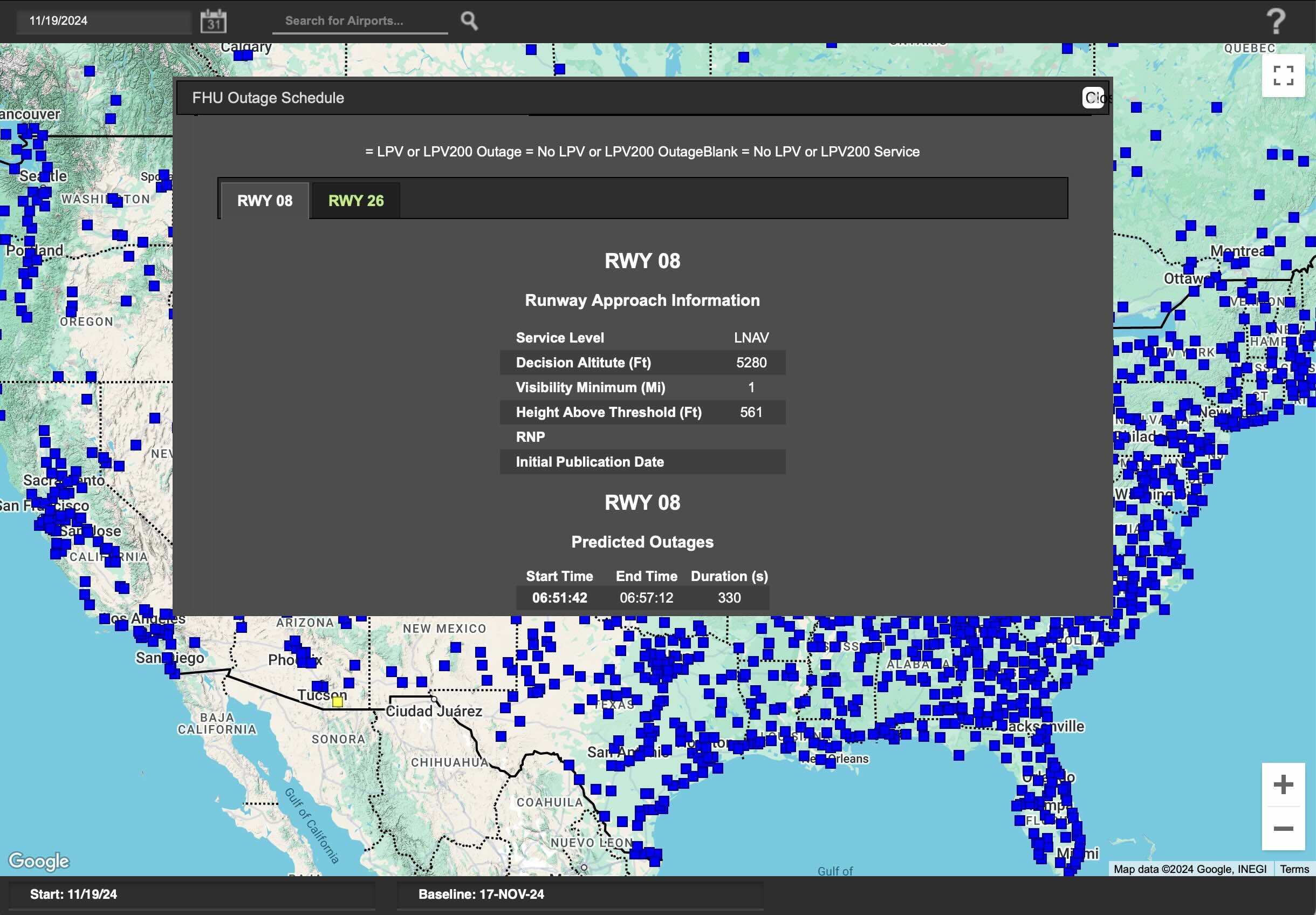
Checking WAAS Availability
- The William J. Hughes Technical Center WAAS Test Team website seems to be the best resource for checking WAAS availability
- The Airport Schedules application seems to be the easiest way to determine WAAS availability
Determining GPS Receiver Capabilities
Check AFM/POH
- See, for example on a Cessna 172S G1000, the POH Section 2 - G1000 LIMITATIONS - GPS-WAAS for more info.
- In the Garmin G1000 NXi Pilot's Guide for the PA-28-181 Archer see the System Overview section
Check aircraft receiver
In the Garmin G1000 NXi Pilot's Guide for the PA-28-181 Archer it describes the PRN (pseudo-random noise, the unique ID identifying the satellite) and signal strength bars
As the GPS receiver locks onto satellites, a signal strength bar is displayed for each satellite in view, with the appropriate satellite PRN number (01-32 or 120-138 for WAAS) below each bar.
The signal strength bars are described on page 20, but a solid green bar means the satellite is being used
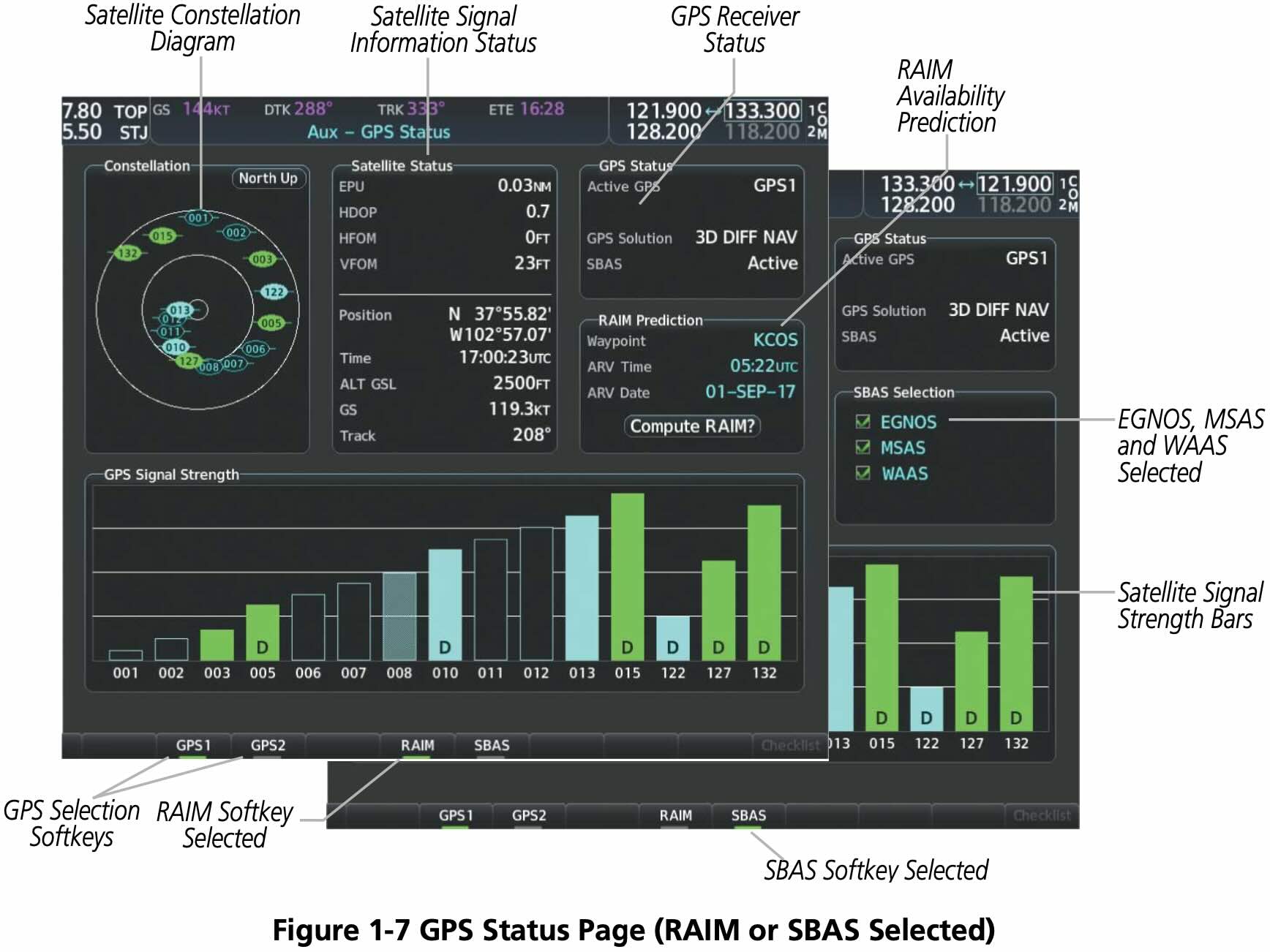
- WAAS satellite PRN 138 was decommissioned in May 2022 and replaced by PRN 135
Using GPS During IFR Operations
- Verify database is current
- See the exception in AIM Table 1-1-6 that allows flying with an expired GPS database
- Verifying approaches haven't changed or been amended
- Verifying route hasn't changed
- See the exception in AIM Table 1-1-6 that allows flying with an expired GPS database
- Check RAIM or WAAS
Using GPS for Non-GPS Approaches
GPS can be used in lieu of a VOR for a VOR approach if the underlying NAVAID is monitored for final approach segment coarse alignment
AIM 1-2-3(c) Note 5
Use of a suitable RNAV system as a means to navigate on the final approach segment of an instrument approach procedure based on a VOR, TACAN or NDB signal, is allowable. The underlying NAVAID must be operational and the NAVAID monitored for final segment course alignment.
If a DME fix on a Localizer approach isn't in the GPS database you may only define that fix using GPS distance from the localizer antenna
TIP
To satisfy the requirement that the NAVAID underlying frequency be monitored on the final approach course, tune the VOR use the bearing pointers, and ensure they align with guidance provided by GPS.
GPS Failures
- On the G1000, the GPS flight phase (e.g.
ENR,TERM,LPV) is shown on the HSI to the right of the CDI - Normally this text is magenta
- If cautionary conditions exist this text will be in amber
- the
LOI(Loss of Integrity Monitoring) indication appears to the right of the HSI when GPS integrity is insufficient for the current phase of flight
Radar Assistance to VFR Traffic
- ATC provides a variety of services to participating VFR aircraft on a workload permitting basis.
- Participating aircraft must be able to communicate with ATC, be within radar coverage, and be radar identified.
- Services provided include
- VFR radar traffic advisory service (flight following) and safety alerts
- Vectoring (when requested)
- Terminal radar programs (TRSA) to separate all participating VFR aircraft and IFR traffic
- Radar assistance to lost aircraft
- Class C services include separation between IFR/VFR traffic, and sequencing of VFR traffic to the airport
- Class B services include separation based on IFR/VFR and/or weight, and sequencing of VFR arrivals
Transponder
- A transponder is a radar beacon transmitter/receiver installed in the instrument panel.
- ATC beacon transmitters send out interrogation signals continuously as the radar antenna rotates.
- When an interrogation is received by a transponder, a coded reply is sent to the ground station where it is displayed on the controller's scope.
- A reply light on the transponder panel flickers every time it receives and replies to a radar interrogation. Transponder codes are assigned by ATC.
- Transponders used in general aviation are mode A
- If it can do altitude encoding it has mode C capability
- Mode C sends pressure altitude to ATC
- Adjusting the altimeter's Kollsman window has no effect on the altitude read by the controller.
- A transponder code consists of four numbers from 0 to 7 (4,096 possible codes)
- Mode S transponder sends/receives some extra data
- Mode S offers improvements over Mode C
- 24-bit addresses instead of 4-bit
- Transmits more data
- Aircraft Collision Avoidance System (ACAS)
- Heading, roll angle, etc.
Requirements
- Must have transponder with mode C in
- Class A, B, and C airspace
- Above 10,000 MSL, except when 2,500 AGL.
- Within 30 nm of class B primary airports (in and above the mode-C veil)
- Within 10 nm of certain designated airports, excluding airspace which is both outside the Class D surface area and below 1,200' AGL
- Flying into, within, or across the ADIZ
Comparison Against ADS-B Requirements
- Mode-C is required in the same places as ADS-B except it is all airspace at or above 10,000 feet MSL, excluding airspace at and below 2,500 feet AGL (not just class E).
- Mode-C is not required in the Gulf of Mexico area specified for ADS-B.
- Mode-C is required into/within/across the ADIZ
ADS-B
ADS-B
A surveillance technology in which an aircraft determines its position via satellite navigation or other sensors and periodically broadcasts it, enabling it to be tracked.
- ADS-B uses plane's WAAS GPS and broadcasts information to other planes and ground stations.
- Ground stations compile and rebroadcast received information.
- This is known as ADS-B Out.
- ADS-B In is the capability for other planes to receive this information as traffic, as well as weather information.
- Acronym
- Automatic - no pilot input required
- Dependendent - requires positon input, e.g. WAAS GPS
- Surveilance - provides aircrafts location, direction, and climb/descent indication
- Broadcast - broadcasts the surveilance information to be seen by others
- Components of ADS-B In
- Traffic Information Services-Broadcast (TIS-B)
- Provides traffic information to planes with ADS-B receivers.
- The traffic includes that which is not broadcasting its own output via ADS-B, because it's able to use radar data and conventional transponder data to understand where aircraft are.
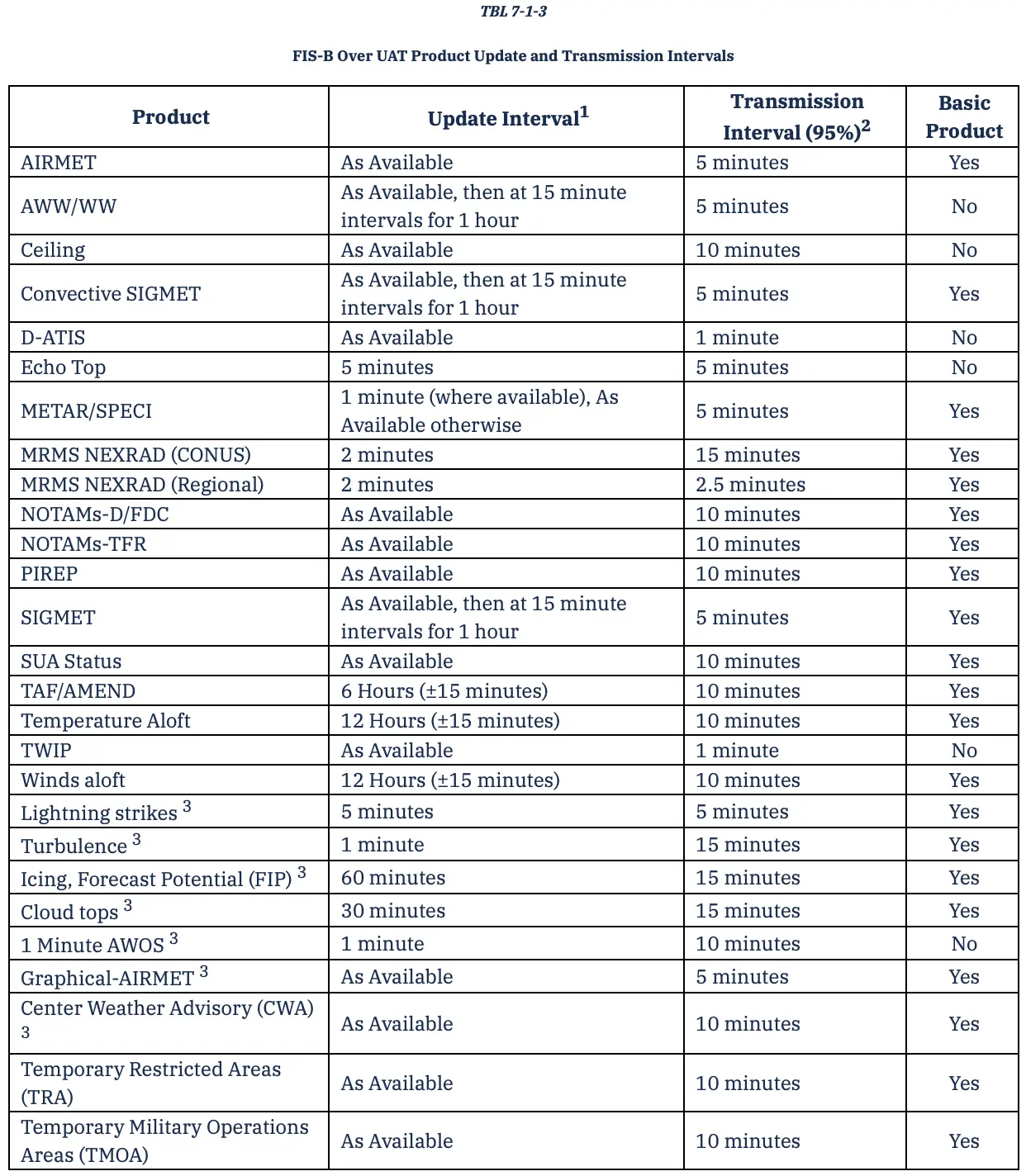
- Flight Information Services-Broadcast (FIS-B)
- Provides NEXRAD graphical weather in (for example in G1000).
- Also provides info on SUA and TFRs.
- Traffic Information Services-Broadcast (TIS-B)
- FAA Automatic Dependent Surveillance-Broadcast (ADS-B)
- FAA Equip ADS-B
- 978 and 1090 MHz
FIS-B
Requirements
- ADS-B is required in:
- Class A, B, and C airspace.
- Class E airspace at or above 10,000 feet MSL.
- Excluding airspace at and below 2,500 feet AGL.
- Within 30 nautical miles of a Class B primary airport (the Mode C veil).
- Above the ceiling and within the lateral boundaries of Class B or Class C airspace up to 10,000 feet.
- Class E airspace over the Gulf of Mexico, at and above 3,000 feet MSL, within 12 nm of the U.S. coast.
- 14 CFR §91.225 - Automatic Dependent Surveillance-Broadcast (ADS-B) Out equipment and use
- 14 CFR §91.227 - Automatic Dependent Surveillance-Broadcast (ADS-B) Out equipment performance requirements
References
- FAA-H-8083-25B Pilot's Handbook of Aeronautical Knowledge
- FAA-H-8083-15B Instrument Flying Handbook
- Chapter 9: Navigation Systems
- Aeronautical Information Manual
- FAA-AC-20-138D Airworthiness Approval of Positioning and Navigation Systems
- FAA-AC-90-105A Approval Guidance for RNP Operations and Barometric Vertical Navigation in the U.S. National Airspace System and in Oceanic and Remote Continental Airspace
- FAA-AC-90-108 Use of Suitable Area Navigation (RNAV) Systems on Conventional Routes and Procedures
- FAA-AC-90-100A U.S Terminal and En Route Area Navigation (RNAV) Operations
- RAIM Service Availability Prediction Tool (SAPT) Summary Page
- FAA-H-8083-3C Airplane Flying Handbook
- Private Pilot - Airplane Airman Certification Standards (FAA-S-ACS-6B)
- FAA Aeronautical Chart Users' Guide
- VFR Raster Charts
- Aeronautical Charts
- Foreflight
- AOPA Chart Symbols PDF