Instrument Proficiency Check
Introduction
- This document follows the FAA Instrument Proficiency Check (IPC) Guidance from March 2010
- Instrument currency is maintained by accomplishing the following in last 6 calendar months (66 HIT)
- Within preceding 6 calendar months
- 6 - 6 instrument approaches
- H - Holding procedures and tasks
- I - Intercepting and
- T - Tracking courses through the use of navigational electronic systems
- 14 CFR 61.57(c)
- Per aircraft category
- e.g. Airplane, rotorcraft
- Within preceding 6 calendar months
- After instrument currency lapses, there is a six-month "grace period" where a pilot can regain their instrument currency
- After this six-month "grace period" an IPC is required
- 14 CFR §61.57(d)(1)
- FAA-AC-61-98E Currency Requirements and Guidance for the Flight Review and Instrument Proficiency Check
- Gives a list of areas to cover during an IPC
- FAA-S-ACS-8C Instrument Rating Airplane Airman Certification Standards
- Provides the areas of operation to cover during an IPC
- FAA-AC-61-65H Certification: Pilots and Flight and Ground Instructors
- Gives the required endorsement upon satisfactory completion of an IPC
- No logbook entry reflecting unsatisfactory performance is required
- Just log it as dual given
Preflight Action
Preflight Information
- Before a flight, PIC must become familiar with all available information concerning that flight which includes (NWKRAFT)
- N - NOTAMs
- W - Weather
- Reports and forecasts
- K - Known traffic delays
- As advised by ATC
- See FAA National Airspace System Status
- R - Runway lengths
- Of intended use
- A - Alternates
- Available
- F - Fuel requirements
- T - Takeoff and landing performance
- Data
- The above list though is not comprehensive
- Route of flight and altitude
- Airspace
- Obstacles
- Airport environment at destination (taxi destination)
- Planned instrument approach procedures and potential alternate approaches that might be likely
- 14 CFR §91.103 - Preflight action
- IFR Fuel Requirements
- Be able to fly to first airport of intended landing, then to the alternate, and still have 45 min reserve at normal cruise.
- 14 CFR §91.167 - Fuel requirements for flight in IFR conditions
Weather Briefing
- How to obtain a weather briefing
- Weather products availabe
- How to use briefing as part of good ADM
Required Equipment and Airworthiness
Day VFR Required Equipment
- 14 CFR §91.205(b)
- A-TOMATO FLAMES
- A - Anti-collision lights
- If newer than 1996
- T - Tachometer
- For each engine
- O - Oil temperature gauge
- For each engine
- M - Manifold pressure gauge
- For altitude engine
- A - Airspeed indicator
- T - Temperature gauge
- For liquid cooled engines
- O - Oil pressure gauge
- F - Fuel level gauge
- L - Landing gear position indicator
- Retractable only
- A - Altimeter
- M - Magnetic direction indicator
- Compass
- E - ELT
- S - Seatbelts
- Shoulder harnesses in front seat if newer than 1978
- A - Anti-collision lights
- Note: Transponder required above 10,000 MSL, unless witihin 2,500 AGL. Also in A, above B mode-C veil, and in C airspace.
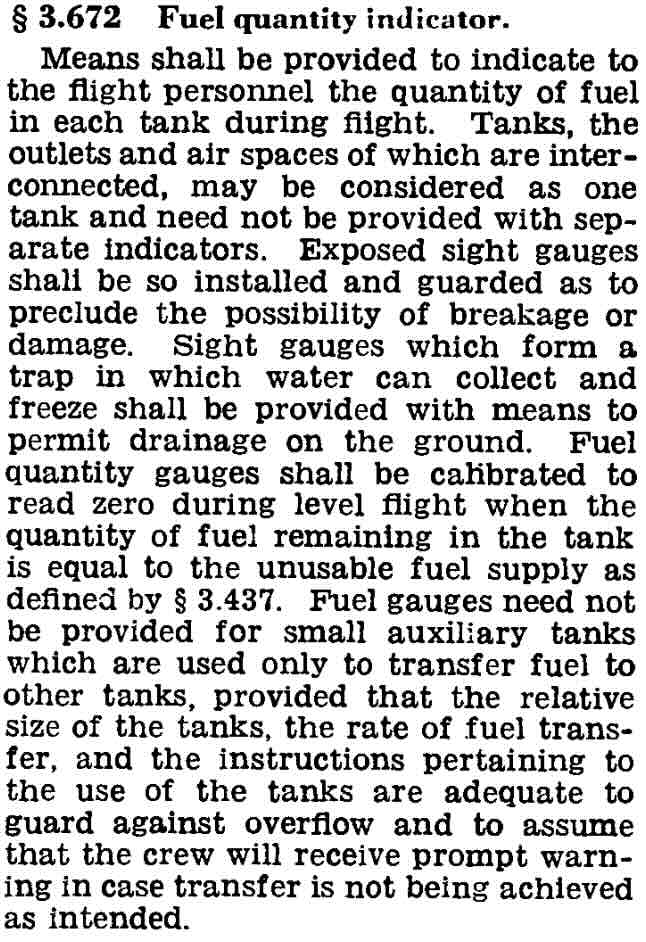
Note on Fuel Gauges
This note exists to provide some context around statements regarding the required accuracy of fuel gauges.
The below provides some excerpts of the regulations around fuel gauges depending on which set of regulations a given aircraft are certified under.
This is the most recent CFR for normal category airplanes that gives fuel gauge requirements.
Each fuel system must— Provide the flightcrew with a means to determine the total useable fuel available and provide uninterrupted supply of that fuel when the system is correctly operated, accounting for likely fuel fluctuations;
The relevant CFR prior to the Part 23 rewrite that went into effect on August 30, 2017.
Fuel quantity indication. There must be a means to indicate to the flightcrew members the quantity of usable fuel in each tank during flight. An indicator calibrated in appropriate units and clearly marked to indicate those units must be used.
Night VFR Required Equipment
- 14 CFR §91.205(c)
- FLAPS (In addition to day VFR)
- F - fuses
- L - landing light
- If for hire
- A - anti-collision lights
- P - position lights
- Nav lights
- S - source of power
IFR Required Equipment
- 14 CFR §91.205(d)
- GRABCARDD
- G - Generator
- Or alternator
- R - Radios
- Comm and navigation suitable for the route to be flown
- A - Altimeter
- Adjustable
- B - Ball
- Inclinometer, slip/skid indicator
- C - Clock
- With seconds
- A - Attitude indicator
- R - Rate of turn indicator
- D - Directional gyro
- Heading indicator
- D - DME or RNAV
- At FL240 and higher if VOR is required
- G - Generator
Additional Night Lighting Requirements
- Regarding lights see also 14 CFR §91.209 Aircraft lights
- No person may, from sunset to sunrise, park or move an aircraft in, or in dangerous proximity to, a night flight operations area of an airport unless the aircraft:
- Is clearly illuminated
- Has lighted position lights
- Or is in an area that is marked by obstruction lights
- Basically when pushing the plane around at night with the towbar, for example, unless the area is well lit, leave the nav lights on.
Note: this is a good example where there are grey areas in the definitions, for example how clear is "clearly illuminated" so the obvious thing to do if in doubt at all is just leave the nav lights on.
What is a night flight operations area? Absent any proffered definition, the plain reading of the phrase-as I read it-would be an area used, or subject to use, for flight operations at night. In other words, any public use airport with an apron or taxiway that is open to flight operations at night could and should be considered-by my reading-a night flight operations area. Whether the area is a movement or non-movement area shouldn't matter. Could someone else reasonably taxi past you (or into you!) at night? That's probably a night flight operations area.
Inoperative Equipment Overview
When thinking about what equipment is required first think of 14 CFR §91.7 - Civil aircraft airworthiness that says:
No person may operate a civil aircraft unless it is in an airworthy condition. The pilot in command of a civil aircraft is responsible for determining whether that aircraft is in condition for safe flight
So if you have any reason to think the aircraft is not safe to fly due to some inoperative equipment, don't fly it.
Regulations should be a floor for safety not a ceiling.
Minimum Equipment List (MEL)
- A minimum equipment list is a list of equipment approved by the manufacturer and the FAA, by which you may legally operate a flight with inoperative equipment.
- Requirements below are when an aircraft needs an MEL
- No aircraft can fly with inoperative equipment unless it has an approved minimum equipment list (MEL)
- Exception:
- Non-turbine planes (and some other aircraft) as long as the inoperative equipment is not required by 14 CFR §91.205
- And not required by type certificate or Airworthiness Directive (AD)
- Marked as "INOP"
- If the aircraft does not have an MEL can follow 14 CFR §91.213 which says for non-turbine planes (and some other aircraft) as long as the inoperative equipment is not required by 14 CFR §91.205 and not required by type certificate or Airworthiness Directive (AD) it can be marked as "INOP" and the aircraft can still be flown.
- If missing any items in MEL must get authorization from FSDO
Kind of Operations (Equipment) List (KOL or KOEL)
- Indicates equipment required for airworthiness during the kinds of operations (e.g. VFR/IFR, day/night)
- The Cessna 172SP, for example, which contains a KOEL in Section 2 of the POH indicates that strobes are required for all flight conditions.
- If our aircraft has a KOEL it will be in the POH?
- Indicates equipment required for airworthiness during the kinds of operations (e.g. VFR/IFR, day/night)
Comprehensive Equipment List (CEL)
- For example in the weight and balance section of C172SP POH
- It is a comprehensive list of equipment in the aircraft and identifies those items that are required by CFRs for FAA certification
- Is this actually any different than the minimum required by FAA? Or is Cessna imposing additional requirements beyond the FAA with this list?
- Is this the same as KOEL?
Supplemental Type Certificate (STC)
- FAA authorization to modify aircraft (e.g. install new avionics)
- Might come with additional requirements, e.g. keep PFD manual in plane
This has interesting discussion about what equipment needs to be working in particular on intermittently working equipment Minimum Equipment: What Has to be Working?
A good way to approach required equipment on the aircraft is to think through a hypothetical situation of preflighting an aircraft prior to a flight, finding a piece of equipment inoperative, and then determining whether or not the aircraft can still be flown with said equipment inoperative.
Determining Airworthiness
- The following flowchart captures most of the questions that need to be answered in this situation.
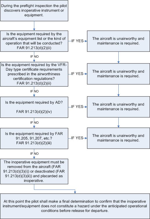
- The following list is similar to the questions in the flowchart.
- The order in which these questions are asked does not matter.
- Does the plane have an MEL?
- Minimum equipment list, approved by FAA
- General aviation planes will almost certainly not have an MEL
- Does the plane have a KOEL (kinds of equipment list)?
- G1000/nav com III POHs do, start there (section 2 POH, operating limitations)
- Does the plane have a CEL (comprehensive equipment list)?
- 172R/S/M/N/P (section 6 POH, weight and balance, R required for flight, S standard)
- Is it required by 14 CFR §91?
- 14 CFR §91.205, 14 CFR §91.207, etc.?
- A+TOMATOFLAMES, FLAPS, etc.
- Is it required by Airworthines Directive?
- Is it required by STC?
- Finally, is it required to fly safely?
- See 14 CFR §91.7
- Does the plane have an MEL?
- If it legal to fly with the inoperative equipment, it must be placarded and either removed or deactivated, if it is removed, a new weight and balance might need to be computed depending on the weight of the part.
FAA-AC-91-67A Minimum Equipment Requirements for General Aviation Operations Under FAR Part 91
Deactivation. When an item is "deactivated" or "secured," or both, the specified item must be put into an acceptable condition for safe flight. Deactivation may involve more than simply turning off a system switch, which does not remove power from the system. Deactivation may involve pulling and securing the circuit breaker and/or removing the equipment. Deactivation of an inoperative system is not preventive maintenance as described in part 43 appendix A. Regardless of the method of deactivation, a person authorized to approve the aircraft for return to service under § 43.7 must make the maintenance record entry required by § 43.9. No person may operate the aircraft without the entry required by § 43.9.
The safest interpretation of this is that deactivation is not preventative maintenance and therefore not something the pilot can do.
However, the references below may offer other interpretations that might be applied in the case of pulling and securing a circuit breaker in order to deactivate a piece of equpiment.
Specifically, that the act of pulling a circuit breaker, like adding oil to the engine, doesn't even rise to the level of preventative maintentance.
Many preventive maintenance tasks are listed in 14 C.F.R. part 43, appendix A, paragraph (c). The paragraph sets forth in 32 numbered subparagraphs items the FAA has determined to be preventive maintenance. Even though the introductory text of subparagraph (c) states that "[p]reventive maintenance is limited to the following work ...." (emphasis added), in view of the broader definition of preventive maintenance in section 1.1, we believe that such limitation is not controlling. Similarly, for the same reason, we also believe that the following sentence in Advisory Circular 43-12A, Preventive Maintenance (which was referenced in Mr. Hernandez's letter), is overly restrictive That sentence, found in Paragraph 3(b)(l), states: "If a task or maintenance function does not appear in the list, it is not preventive maintenance." As with the other paragraphs of Appendix A (i.e., on major repairs and major alterations), the lists are better viewed as examples of the tasks in each category-they cannot be considered all-inclusive. There are, no doubt, many "simple or minor preservation operations [tasks]" and many "replacement[s] of small standard parts not involving complex assembly operations" performed daily, especially on small general aviation aircraft, that the agency would consider to be preventive maintenance, though they are not included in the 32 listed items.
- Referenced above in Pilot Performed Preventative Maintenance
- In the context of pilots deactivating inoperative systems (e.g. via pulling and securing a circuit breaker) this letter offers some guidance related to things pilots can do which do not even rise to the level of preventative maintenance.
- In the context of this letter, it seems a reasonable position to take that pulling and securing a circuit breaker is the same level as adding oil, and therefore while not preventative maintenance something the pilot can legally do.
14 CFR §91.213(d)(3) also says, "if deactivation of the inoperative instrument or equipment involves maintenance" implying that deactivation may be possible that does not involve maintenance.
Finally, remember about Advisory Circulars from the AIM:
Advisory Circulars ‐ The FAA issues Advisory Circulars (AC) to inform the aviation public in a systematic way of nonregulatory material. Unless incorporated into a regulation by reference, the contents of an advisory circular are not binding on the public.
Aside: a Single Broken Strobe Light
Regarding equipment required by 14 CFR §91.205, it is interesting to note that 14 CFR §91.205(b)(11) says, regarding anticollision light system:
In the event of failure of any light of the anticollision light system, operation of the aircraft may continue to a location where repairs or replacement can be made.
So this is why according to the C172SP KOEL that Strobes are required during all flight conditions.
See also Letts 2017 Legal Interpretation.
Aside: Altimeter Accuracy
Altimeter accuracy requirements +/- 75 ft. for IFR. For VFR not explicitly stated, but it's up to PIC to determine the aircraft is in a safe condition for flight.
Accuracy requirements of altimeter AIM 7-2-3 Altimeter Errors:
If the difference from the known field elevation and the altitude read from the altimeter is plus or minus 75 feet or greater, the accuracy of the altimeter is questionable and the problem should be referred to an appropriately rated repair station for evaluation and possible correction.
From 14 CFR §91.217(a)(2):
- The difference between the automatic reporting output and the altitude displayed at the altimeter shall not exceed 125 feet.
Inspections Required
- Use the AVIATE Acronym to remember required aircraft inspections.
- A - Airworthiness Directives (AD)
- 14 CFR §39
- Need to find all applicable ones and make sure they are complied with
- Can look up FAA Airworthiness Directives (ADs)
- There are third-party services that can provide and help ensure ongoing compliance with ADs by inputting information about a plane
- Airworthiness directives cannot be overflown.
- V - VOR
- Every 30 days for IFR
- 14 CFR §91.171(a)(2)
- VOR accuracy requirements 14 CFR §91.171(b), (c)
- VOT: +/- 4 deg
- Ground checkpoint: +/- 4 deg
- Airborne checkpoint: +/- 6 deg
- Dual check: within 4 deg
- Log the results of the VOR accuracy test in the aircraft logbook or other record including the PADS acronym:
- P - Place
- A - Accuracy (bearing error)
- D - Date
- S - Signature
- I - Inspections
- Annual
- Can not be overflown.
- If annual "expires" and it needs to be flown somewhere for inspection, need a special flight permit (ferry permit).
- Annual can count as 100 hour but not vice versa.
- 100 hour if for hire
- Including flight instruction when the plane and pilot are provided.
- Or progressive
- 100 hour may be overflown to get to a place where inspection may be performed.
- 14 CFR §91.409(a)(1) and 14 CFR §91.409(b)
- Annual
- A - Altimeter/static system
- Every 24 calendar months
- 14 CFR §91.411
- T - Transponder
- Every 24 calendar months
- 14 CFR § 91.413(a)
- E - ELT
- Every 12 months
- 14 CFR §91.207(d)
- Also need to replace/recharge battery at 50% life or after 1 hour of cumulative use
- A - Airworthiness Directives (AD)
Logbook Documentation
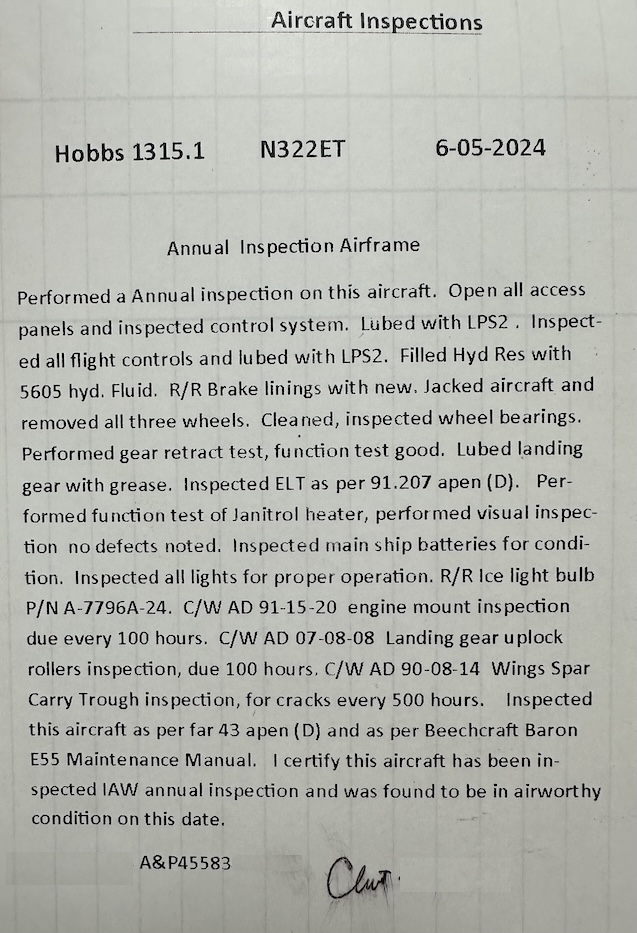
- 14 CFR §43.11
- Things required when inspections are performed
- Type and description.
- Date of inspection and aircraft total time.
- Signature, certificate type and certificate number.
- A statement certifying the aircraft was airworthy for return to service, or list of unairworthy items.
- Things required when inspections are performed
- 14 CFR §43.9
- Similarly, a similar list when maintenance is performed.
- 14 CFR §91.417
- Basically says the aircraft owner must keep these records.
- FAA-AC-43-9C
- This advisory circular provides guidance to help comply with the CFRs above.
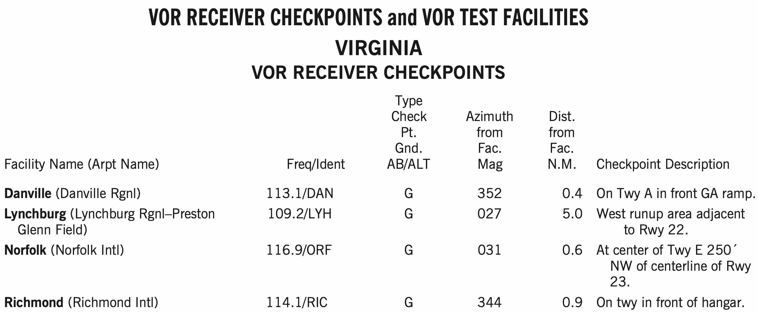
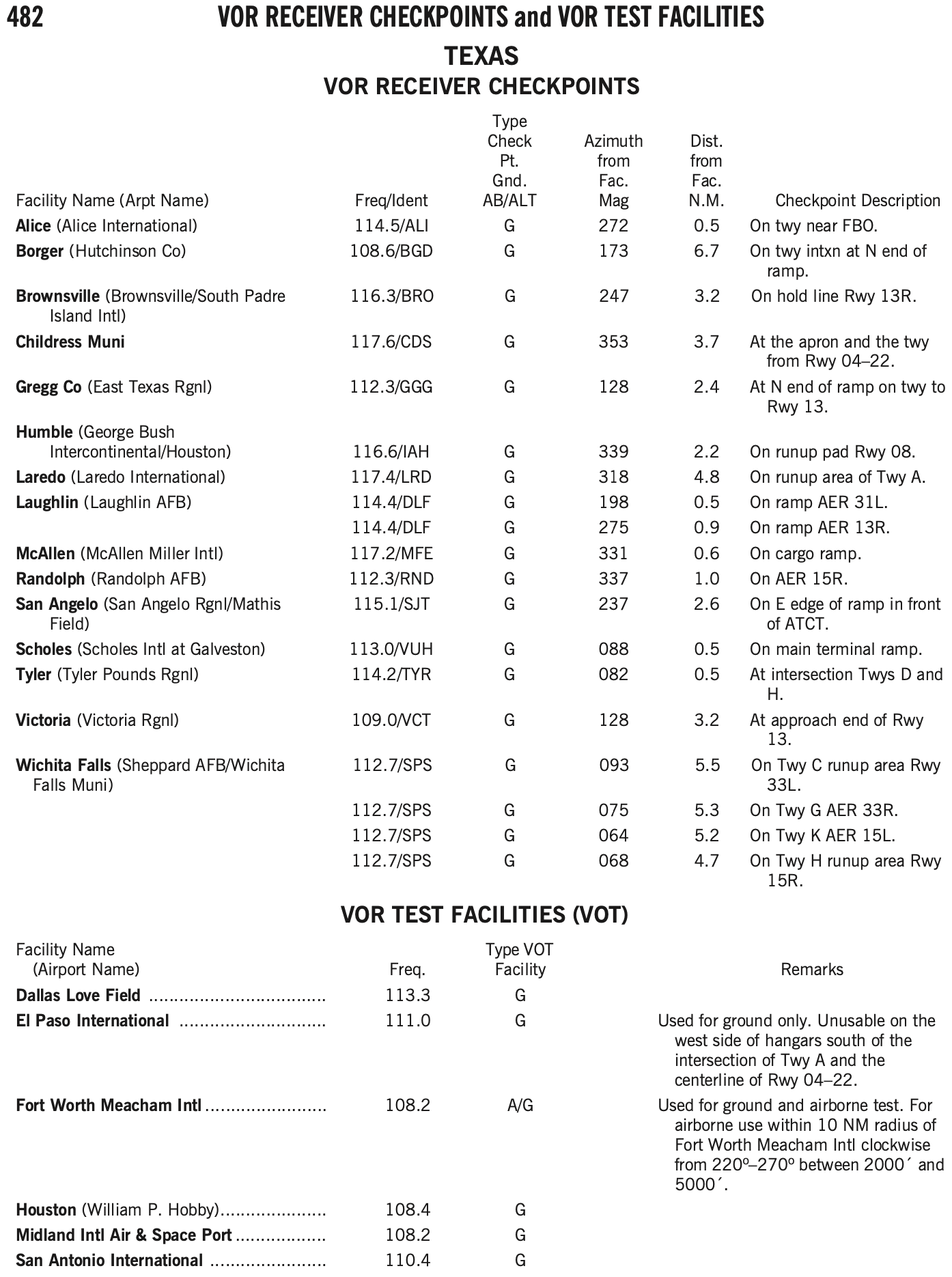
VOR Check
- Recall from AVIATE acronym, VOR needs to be checked every 30 days for IFR
- VOR accuracy requirements 14 CFR §91.171(b), (c)
- VOT: +/- 4 deg
- Can be checked on the ground or in the air, as indicated in the chart supplement for that facility
- Ground checkpoint: +/- 4 deg
- Airborne checkpoint: +/- 6 deg
- Dual check: within 4 deg
- VOT: +/- 4 deg
- Can find VOT facilities and VOR checkpoints in the chart supplement.
- Log the results of the VOR accuracy test in the aircraft logbook or other record including the PADS acronym:
- P - Place
- A - Accuracy (bearing error)
- D - Date
- S - Signature
- VOT is the most convenient way to perform a VOR check if your home airport happens to have one
- Similarly, ground checkpoints are also a convenient option
VOR Ground Checkpoint
- Has a sign in front of the arrow with the radial and frequency

VOT Check
- A VOT is a facility located at certain airports that emits a signal that can be used to test a plane's VOR receiver
- The VOT signals are generally designed to be used while on the ground, but some are designated as usable in air, with certain restrictions
- This information can be found in the chart supplement
- Dial a course of 180° in using the OBS, should see the needle center (within +/- 4 degrees) with a
TOindication.
Performance Calculations
- Be able to use POH to determine aircraft performance given the forecast conditions
- Use calculated performance in ADM
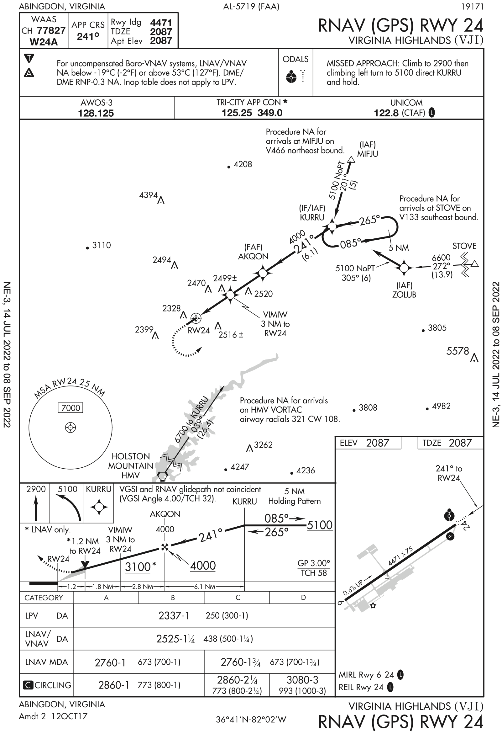
Alternates Under IFR
- Start with the big picture
- Weather depiction chart
- Find the nearest good weather
- Often behind the weather system
- Back up with a forecast
- TAF within 5 nm
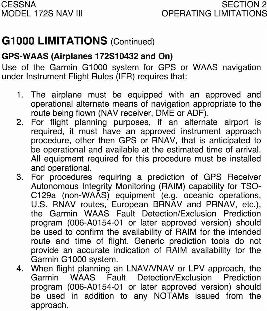
- If flying a non-WAAS-equipped plane, alternate must have an approach other than GPS
- If flying a WAAS-equipped plane, can use an alternate with only GPS approach
- Code 7700 Alternate IAP Requirements
- 14 CFR §91.169(c) - IFR flight plan: Information required
- When is an alternate airport required to be filed on an IFR flight plan
- 1-2-3 rule - an alternate is not required if:
- The desination airport has an IAP and
- From 1 hour before to 1 hour after arrival time weather is predicted to be better than
- 2000 ft ceilings and
- 3 sm visibility
- The desination airport has an IAP and
- If destination does not have an IAP, an alternate is required
- Even if the destination weather forecast is completely clear
- 1-2-3 rule - an alternate is not required if:
- When an alternate is required, then at the estimated time of arrival at the alternate airport, the ceiling and visibility at the alternate airport will be at or above the following weather minima, or it cannot be used as an alternate.
- Whatever is specified as the alternate minimums for that IAP
- If no alternate minimums are specificed:
- Precision approach: 600 ft ceilings, 2 sm visibility
- Non-precision approach: 800 ft ceilings, 2 sm visibility
- Or if there is no IAP, then weather good enough to allow descent from MEA, approach, and landing under VFR.
- Also note that you can file IFR to an airport without an instrument approach, and in this case you must have an alternate no matter what.
- So basically what you do is:
- Determine if alternate is required
- 14 CFR §91.169(a)(2)
- If destination airport doesn't have IAP - you need alternate
- If destination airport does have IAP - apply 1-2-3 rule
- If by the 1-2-3 rule an alternate is not required you are done
- If you need alternate, next have to determine if the desired alternate can be used
- 14 CFR §91.169(c)
- If desired alternate does not have IAP, weather at the ETA must allow descent and landing under VFR to use as alternate
- If desired alternate does have IAP, review it (or multiple IAPs that the aircraft is capable of) and see if there are alternate minimums listed.
- Otherwise apply standard minimums to determine if the desired alternate can actually be used as your alternate based on weather at the ETA
- Determine if alternate is required
- Note: if during flight you arrive at intended destination and cannot land due to current weather, you need not go to the filed alternate. If the weather is different than what was forecast during flight planning and there is a better alternate, use that instead.
- If flying a non-WAAS-equipped plane, alternate must have an approach other than GPS
- If flying a WAAS-equipped plane, can use an alternate with only GPS approach
- AIM 1-2-3(d) Alternate Airport Considerations
- Code 7700 Alternate IAP Requirements
- Discuss ADM around alternate planning
A in the triangle within the first box of the middle briefing strip notes box.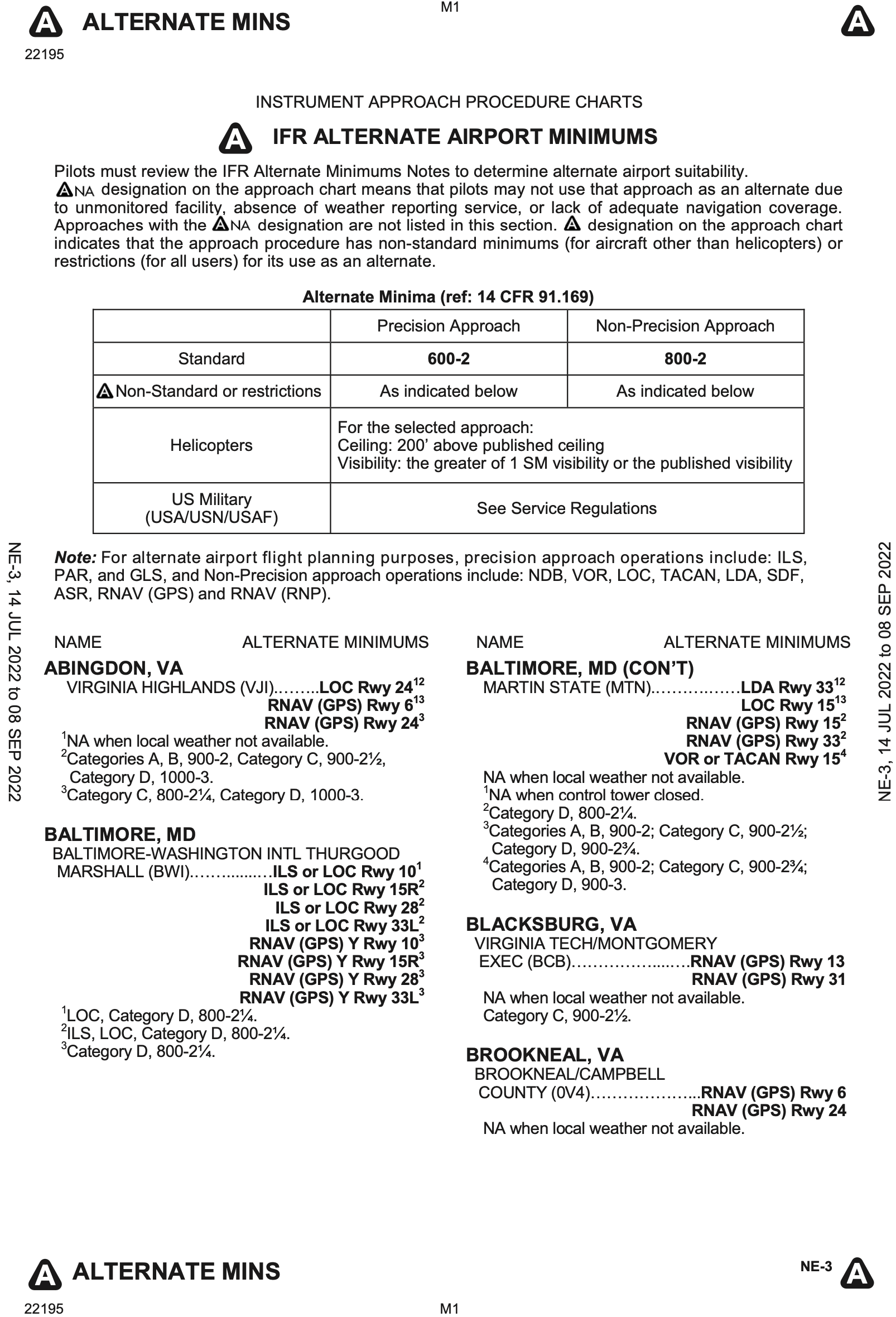
Risk Management and Personal Minimums
- Perceives risk from the four fundamental risk elements or categories (PAVE)
- P ilot
- A ircraft
- en V ironment
- E xternal pressures (mission)
- See personal minimums worksheet
Taxi, Takeoff and Departure
Taxi Procedures and Runway Incursion Avoidance
Departure Procedures
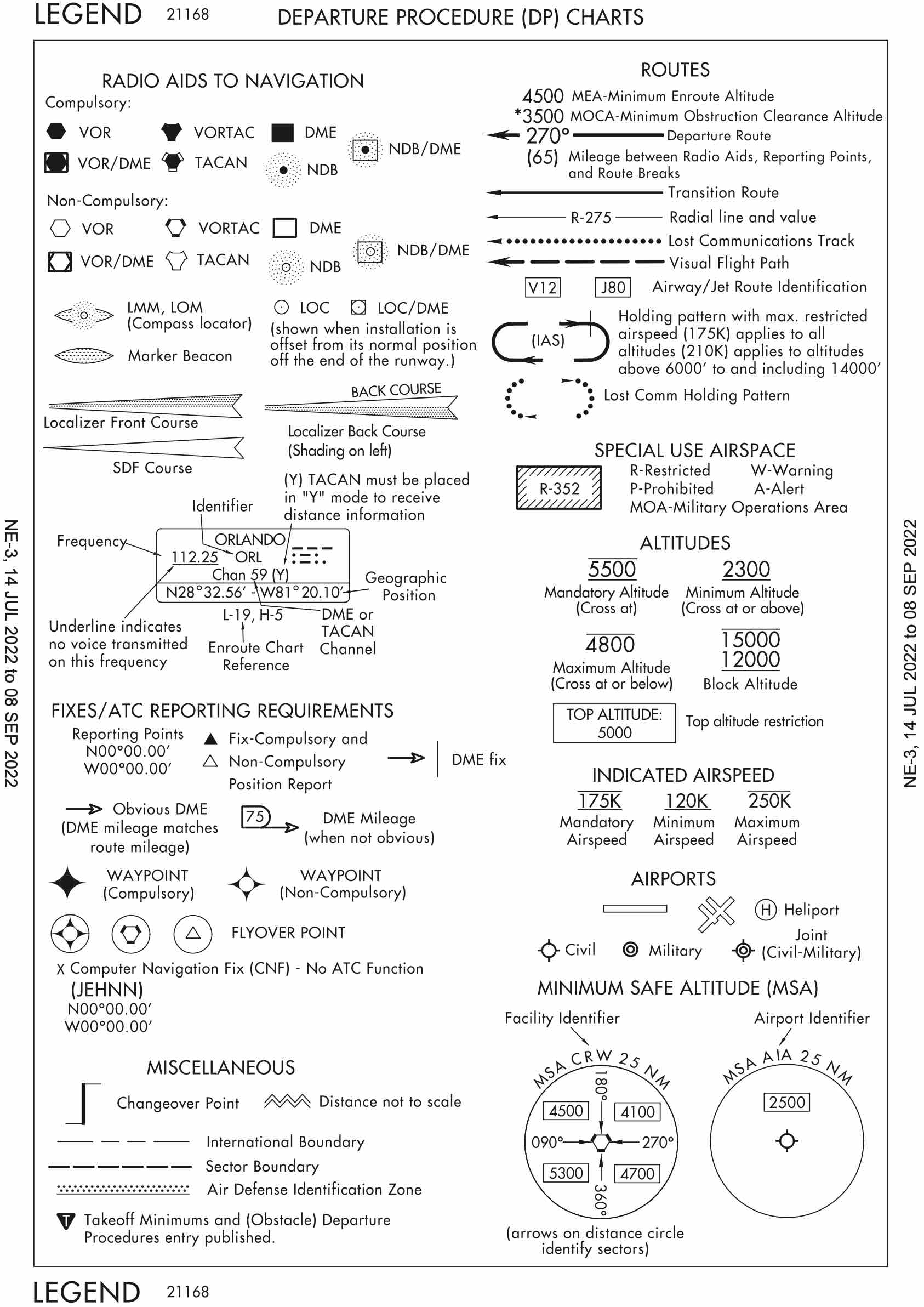
- Find Standard Terminal Arrival Routes (STAR) and Departure Procedures (DP) in the Digital Terminal Procedures Publication
- AIM Section 2. Departure Procedures
- Departure Procedures (DP)
- The generic term for any kind of departure procedure
- Then you have two basic types below, with two subtypes (graphical or textual)
- The two basic types are
- Obstacle Departure Procedures (ODP)
- Standard Instrument Departures (SID)
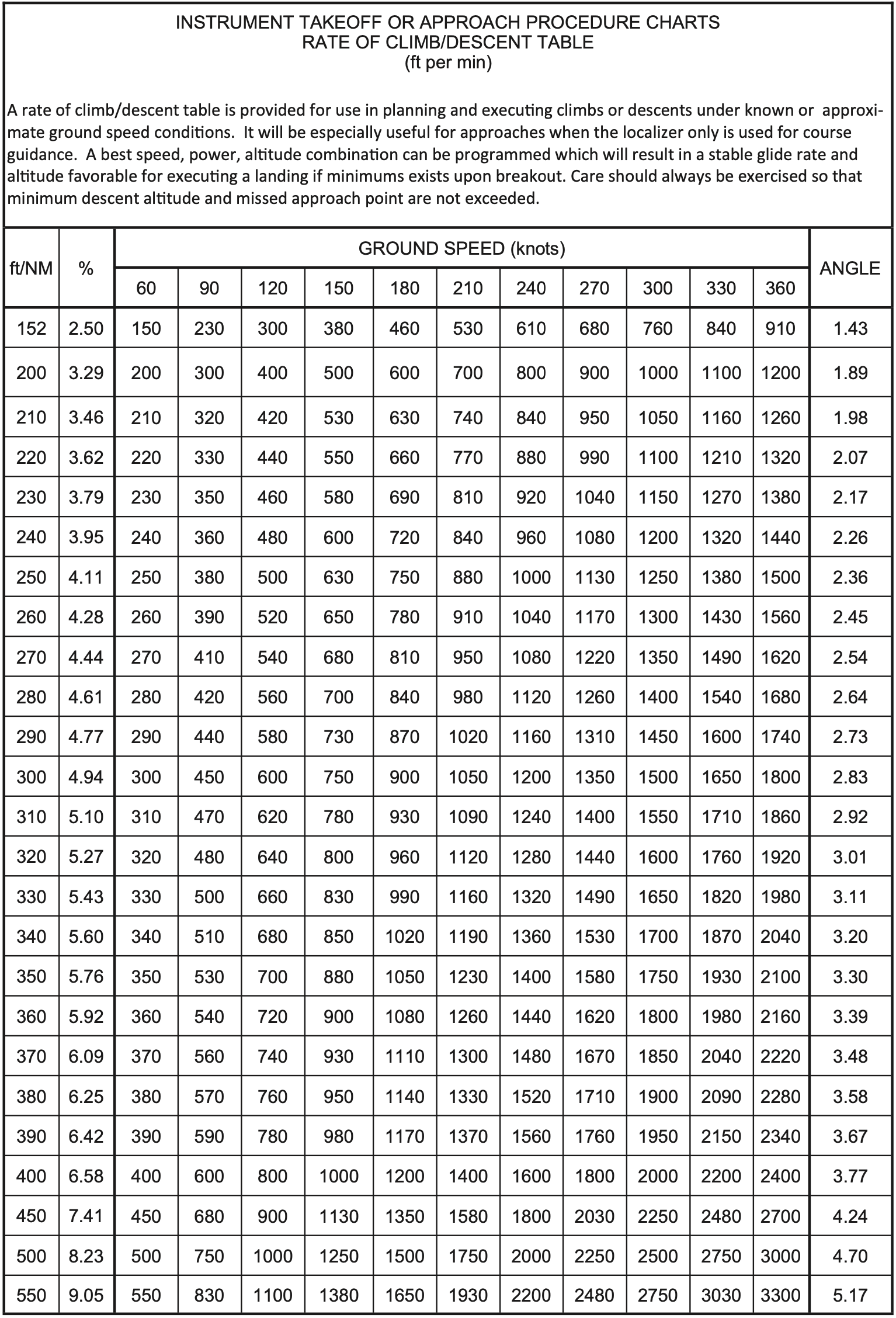
- Departure procedure performance requirements are given in terms of feet per nautical mile.
- To convert those to feet per minute, there is a chart in the back of the Digital Terminal Procedures Publication (d-TPP)/Airport Diagrams
Obstacle Departure Procedures (ODP)
- Purely for obstacle clearance
- Graphical or textual
- ODPs may be flown without clearance
- Generally designed to be available to the largest number of aircraft possible, so they might assume only a VOR receiver and low aircraft performance.
- See
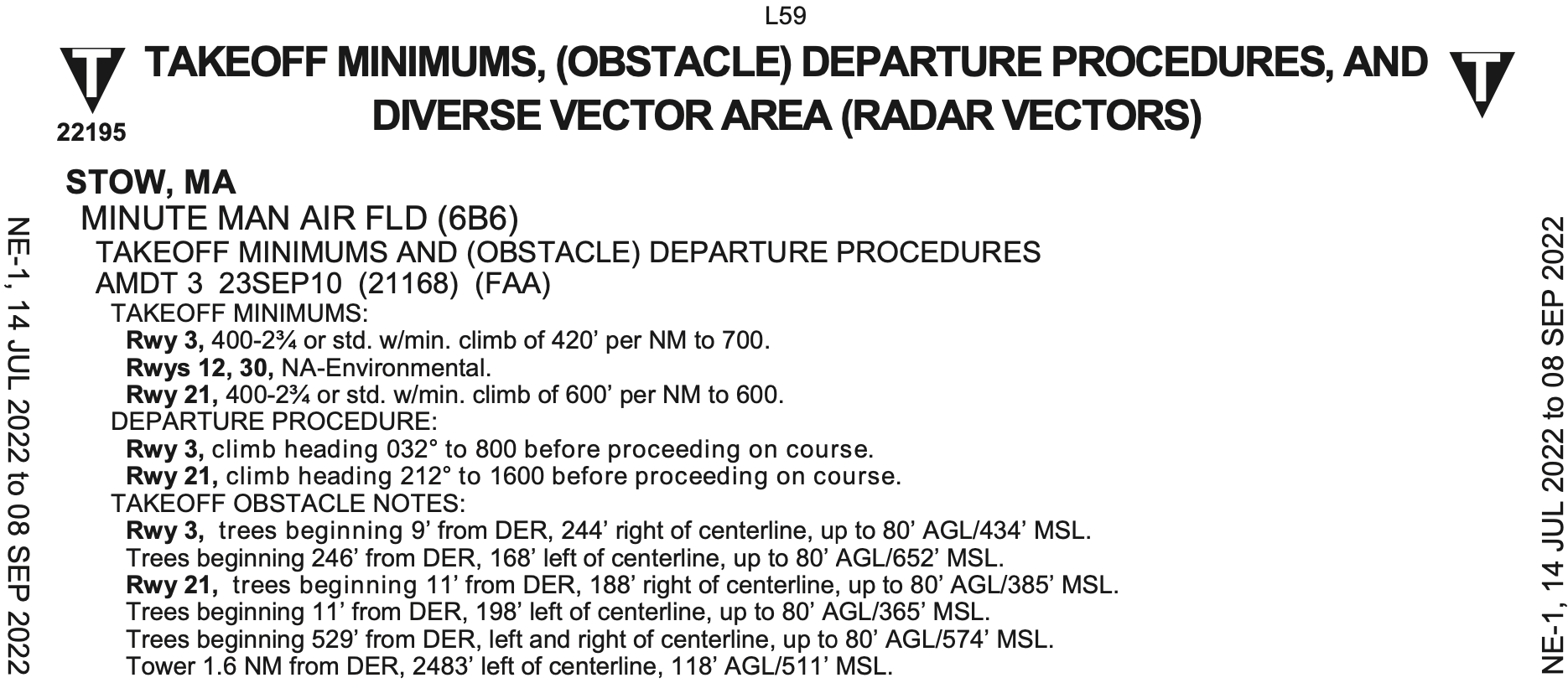
Tin upside down triangle on approach plate for non-standard takeoff minimums or ODP - Textual ODPs
- Those listed in text format in the Takeoff Minimums and Obstacle Departure Procedures section of the Terminal Procedures Publication
- They are usually fairly simple – turn to a heading, intercept a radial, etc.
- Graphical ODPs
- Charted when it would be too complicated to describe them textually
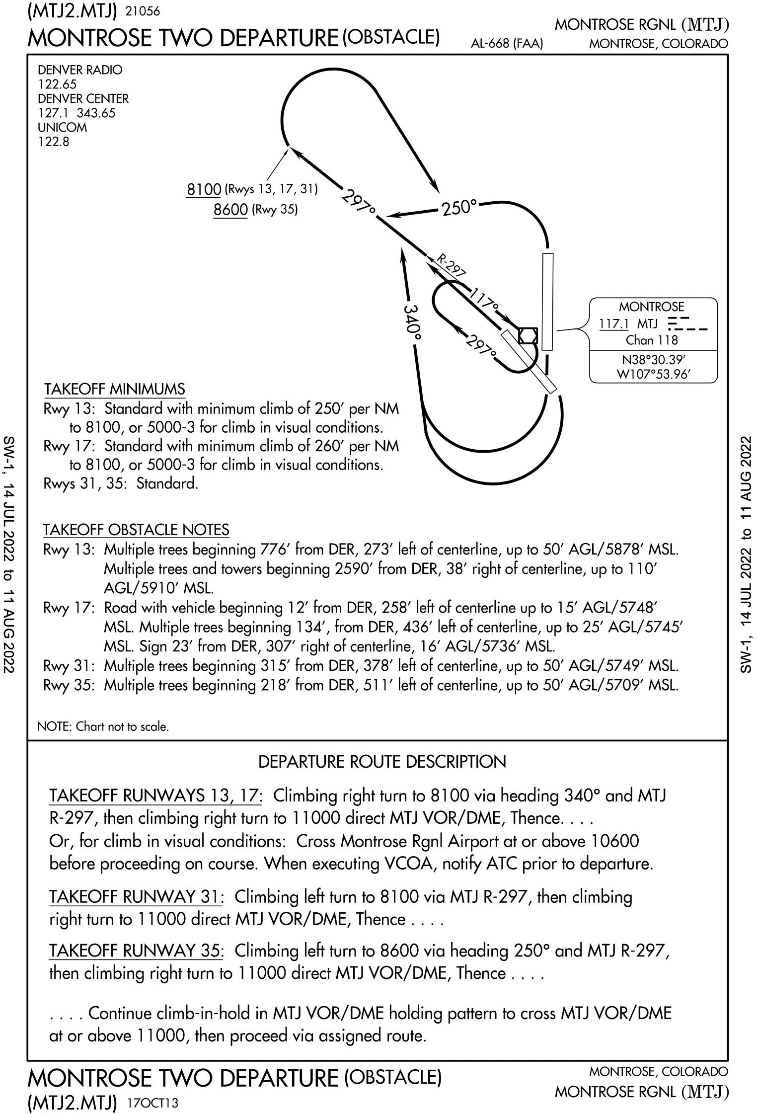
- They include the word (OBSTACLE) in the name, such as the
MONTROSE DEPARTURE (OBSTACLE)out ofKMTJ. - Note the rather tortured routing of the
MONTROSE DEPARTURE (OBSTACLE)designed so that low performance airplanes can hopefully still meet the obstacle clearance requirements.
- Don't need to even fly ODPs, but ATC assumes you will and there's no reason not to
- Climb to 400' AGL before turning
- Must climb at 200' per nm unless otherwise stated
Standard Instrument Departures (SID)
- Exist predominantly for ATC reasons
- Reduces radio traffic and eases traffic flow
- They provide obstacle clearance as well
- Always graphical
- ATC clearance must be received prior to flying a SID
- Given a name, such as the
ARSENAL FIVE DEPARTUREout ofKHEF- This departure is
ARSNL5. - The particular transition is appended to the departure, for example the Martinsburg Transition would be
ARSNL5.MRB.
- This departure is
- The design is based primarily on what is convenient for ATC traffic flow, not whether all airplanes can perform the procedure or not.
- Note they can have some pretty steep climb gradients as well as certain equipment requirements too.
- Climb to 400' AGL before turning
- Must climb at 200' per nm unless otherwise stated
General Departure Notes
- Can decline DP
- If no departure procedure
- Climb to 400' AGL and turn on course
- Must climb at least 200' per nm
- Must be at least 35' AGL at departure end of runway
Takeoff Minimums
- Under Part 91 there are no takeoff minimums except there are performance minimums for the departure you are assigned that you must meet.
- If ATC assigns a departure with performance requirements you cannot meet, you must decline.
- FAA-designated standard minimums for Part 121 and 135
- 1 statute mile (SM) visibility for single- and twin-engine aircraft
- 1⁄2 SM for helicopters and aircraft with more than two engines
- Just because there are no takeoff minimums for Part 91, doesn't mean it's a good idea to take off in zero-zero weather
En Route
Overview
Global Navigation Satellite System (GNSS)
The generic term for satellite based navigation systems used around the world.
- As the title implies, satellite based navigation uses signals from satellites to determine location.
- These satellites are placed in a medium-Earth orbit.
- There are four constellations of such satellites operated by various bodies around the world:
- GPS - United States
- GLONASS - Russia
- Galileo - EU
- BeiDou (BDS) - China
Global Positioning System (GPS)
The particular GNSS system used in the United States.
- Given GPS is the system used in the United States, this document will refer to GPS, but much of what applies to GPS applies to the other GNSS systems as well.
A History of Area Navigation (RNAV)
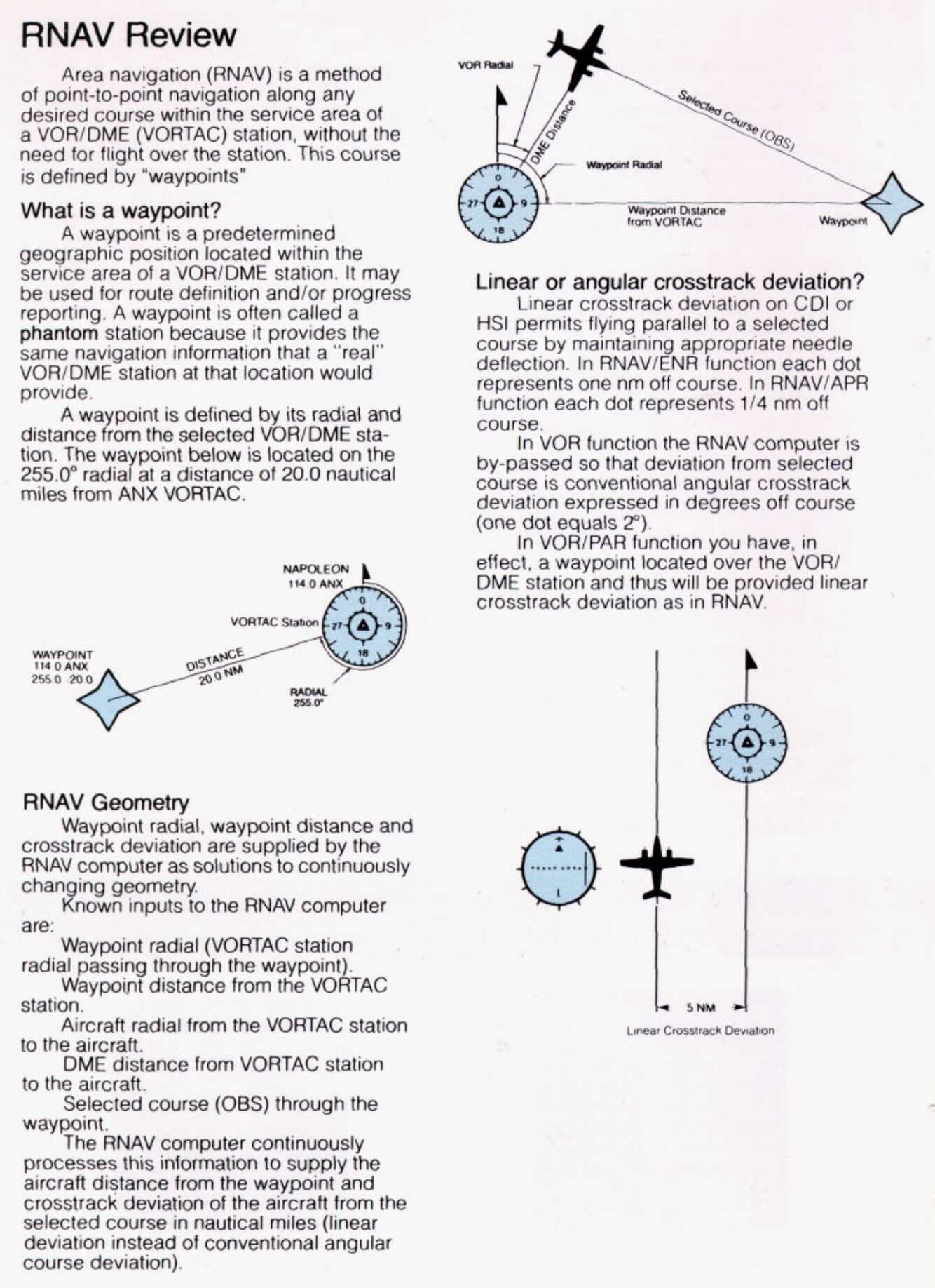
A method of navigation that permits aircraft operations on any desired flight path.
- GPS systems provide a capability called Area Navigation (RNAV) which, unlike using a traditional VOR receiver which only allows flying toward or away from the ground station, allows the navigation between arbitrary points.
- As GPS is overwhelmingly the means by which modern RNAV is possible these terms are often conflated.
- It is important to remember that they are distinct concepts, and while GPS can provide RNAV capability, RNAV systems did exist prior to GPS.
- Methods of area navigation that predate GPS include
- Visual reference (e.g. stars)
- Inertial Navigation Systems (INS)
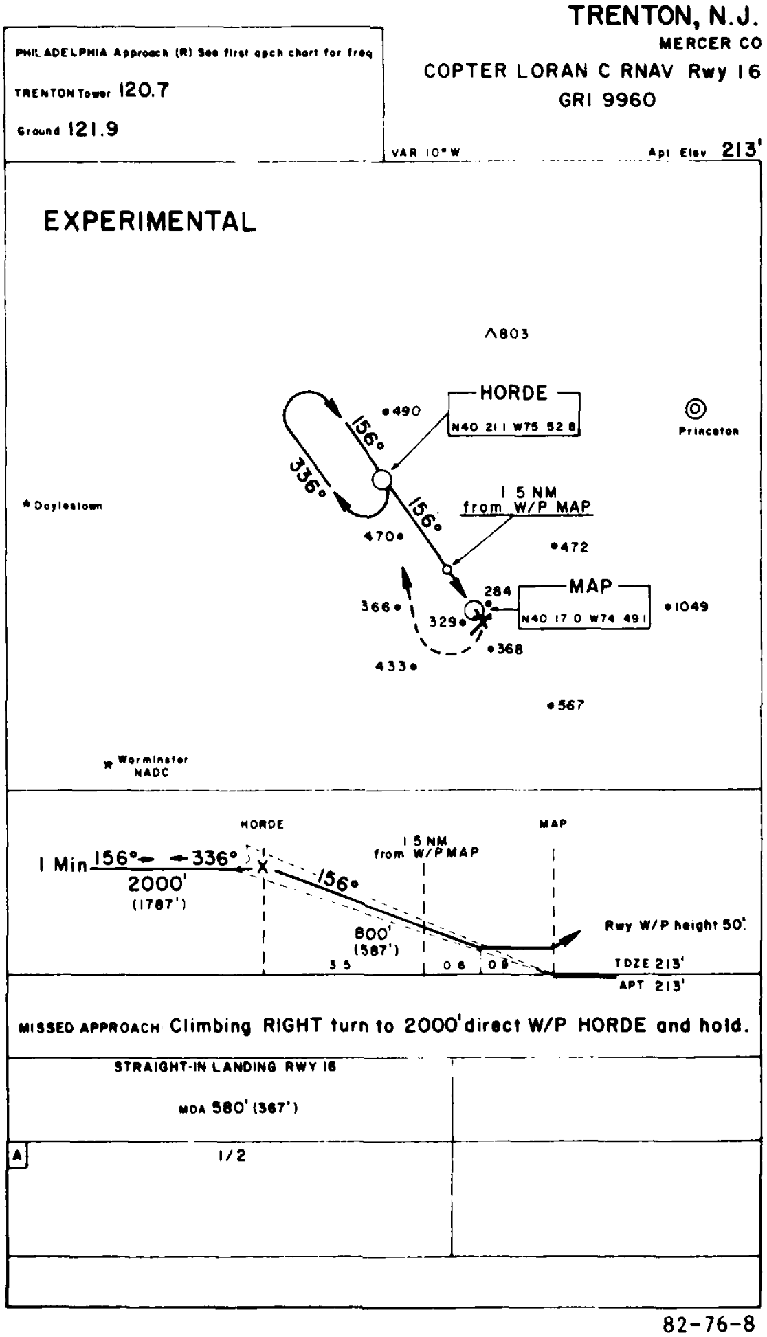
- LORAN C
- See FAA-AC-90-92
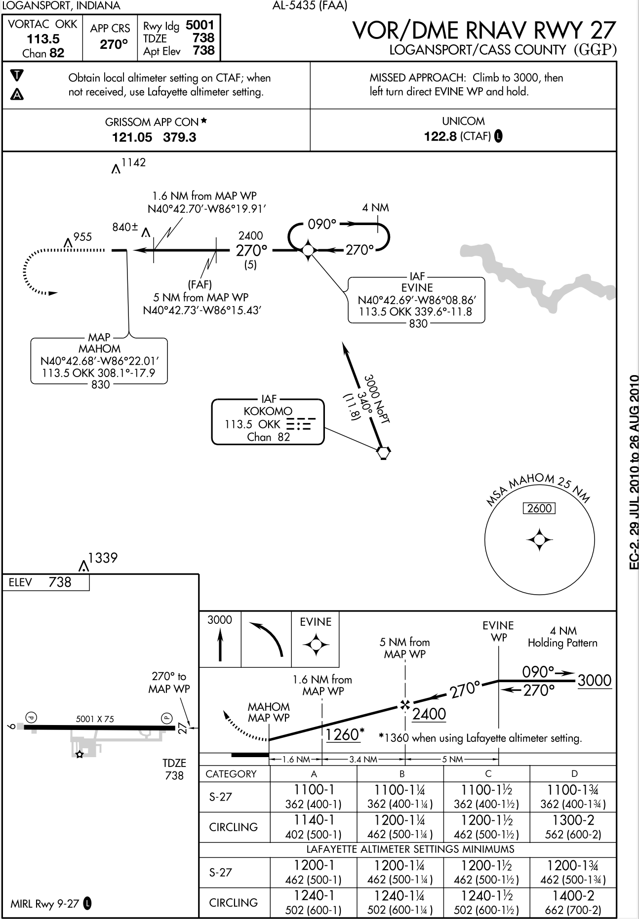
- VOR/DME
- DME/DME
- See FIU RNAV
- Some such VOR based RNAV recievers include
- The Bendix/King KNS 80 Digital Area Navigation System is an RNAV receiver based on VOR
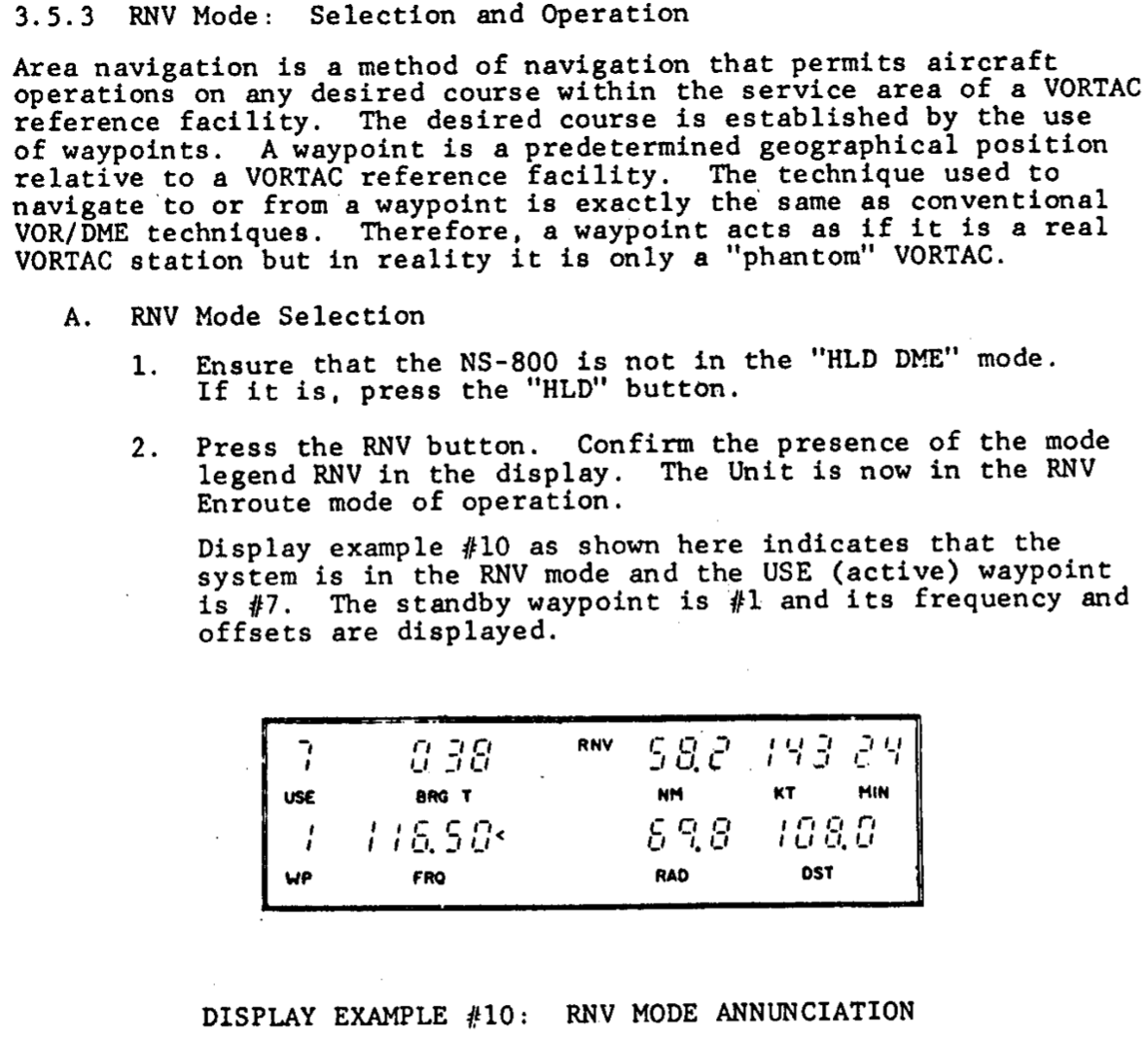
- Narco NS-800
- King KN-74
- They enabled flight between waypoints that were defined by VORs, but without having to fly along the radials of VORs
- FAA-AC-90-45A Approval of Area Navigation Systems for use in the US National Airspace System from 1975 describes guidelines for RNAV systems, well before the existence of GPS
- With a little bit of background on legacy RNAV systems, we can now focus on GPS.
GPS Satellites
- The GPS constellation currently consists of 31 operational satellites
- GPS is designed so that as long as 24 GPS satellites are working, at least 5 should be visible at any time
- AIM 1-1-17(a)(3)(a)
- Need 4 satellites to have GPS
- This gives latitude, longitude, altitude, and time
- Need 5 satellites for RAIM
- More on RAIM below
- Need 6 satellites to remove corrupt GPS signal
- Need 4 satellites to have GPS
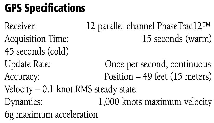
GPS Receiver
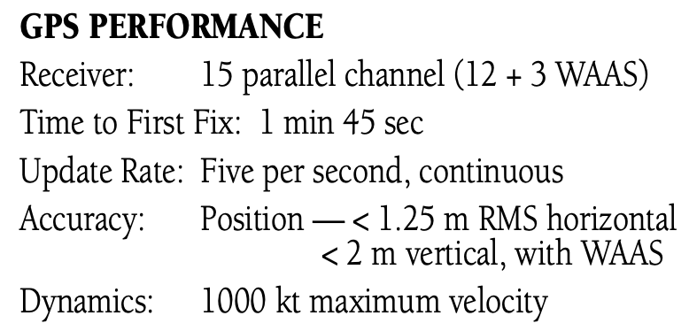
- A typical GPS receiver has at least 12 channels
GPS Database
- GPS databases are updated every 28 days
- Usually every 4th Thursday of the month
- Pilots can update GPS database if they can do it from instrument panel without special tools or disassembly of the unit
- Take the SD card out and update it
Performance Based Navigation (PBN)
Performance Based Navigation (PBN) is comprised of Area Navigation (RNAV) and Required Navigation Performance (RNP) and describes an aircraft's capability to navigate using performance standards.
AIM 1-2-1 says:
PBN exists under the umbrella of area navigation (RNAV). The term RNAV in this context, as in procedure titles, just means “area navigation,” regardless of the equipment capability of the aircraft.
This can be confusing given the difference between RNAV as a concept (area navigation) and RNAV as a navigation specification similar to RNP.
PBN defines a set of standards and doesn't depend on a particular technology.
Therefore, procedures can be defined that depend on these standards and can be used without being changed as new technology is developed.
RTCA DO-229 defines these standards.
These standards, refered to as NavSpecs apply to both aircraft and aircrew.
It also doesn't help that ICAO and the FAA differ somewhat in their use of terminology.
For an aircraft to meet the requirements of PBN, a specified RNAV or RNP accuracy must be met 95 percent of the flight time.
NavSpecs should be considered different from one another, not “better” or “worse” based on the described lateral navigation accuracy.
As a safeguard, the FAA requires that aircraft navigation databases hold only those procedures that the aircraft maintains eligibility for. If you look for a specific instrument procedure in your aircraft's navigation database and cannot find it, it's likely that procedure contains PBN elements your aircraft is ineligible for or cannot compute and fly. Further, optional capabilities such as Radius-to-fix (RF) turns or scalability should be described in the AFM or avionics documents. Use the capabilities of your avionics suite to verify the appropriate waypoint and track data after loading the procedure from your database.
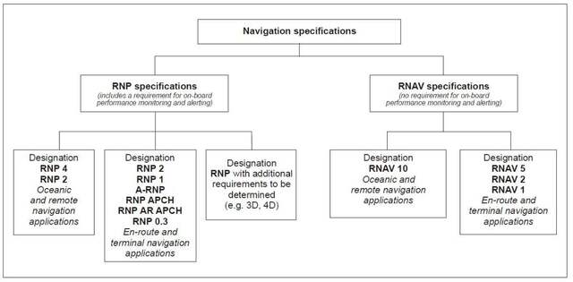
Required Navigation Performance (RNP)
- RNP is a navigation specification under Performance Based Navigation (PBN)
- Three standard RNP levels, where the value is nautical miles each side of centerline that must be maintained for aircraft and obstacle clearance
- RNP 0.3 – Approach
- RNP 1.0 – Departure, Terminal
- RNP 2.0 – En route
- The performance requirements of PBN are conveyed to the operators through navigation specifications, or NavSpecs.
- The values listed above are the lateral limits, in nautical miles, of the errors within which the system must remain 95% of the time
NOTE
RNP Requires
- A specified accuracy be met 95% of the time
- Onboard performance monitoring and alerting
RNAV Navigation Specification
- AIM 1-2-1(a)
- The term RNAV X means a specific navigation specification with a specified lateral accuracy value.
- No requirement for onboard performance monitoring and alerting.
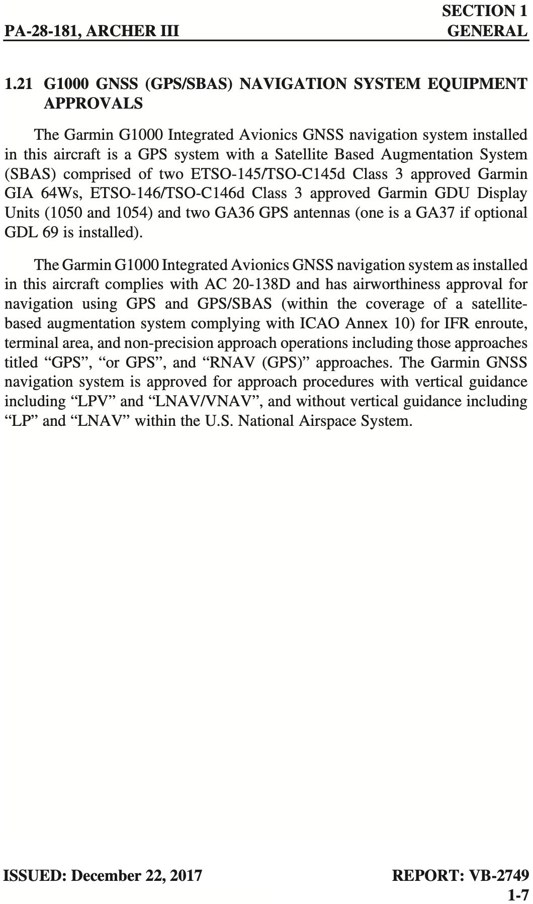
Aircraft Equipment Requirements
- The Piper Archer III NXi G1000 system satisfies the following requirements:
- RNP APCH (without RF)
- RNP 1 (terminal operations)
- RNAV 1 and RNAV 2
- RNP-10 (oceanic and remote continental operations)
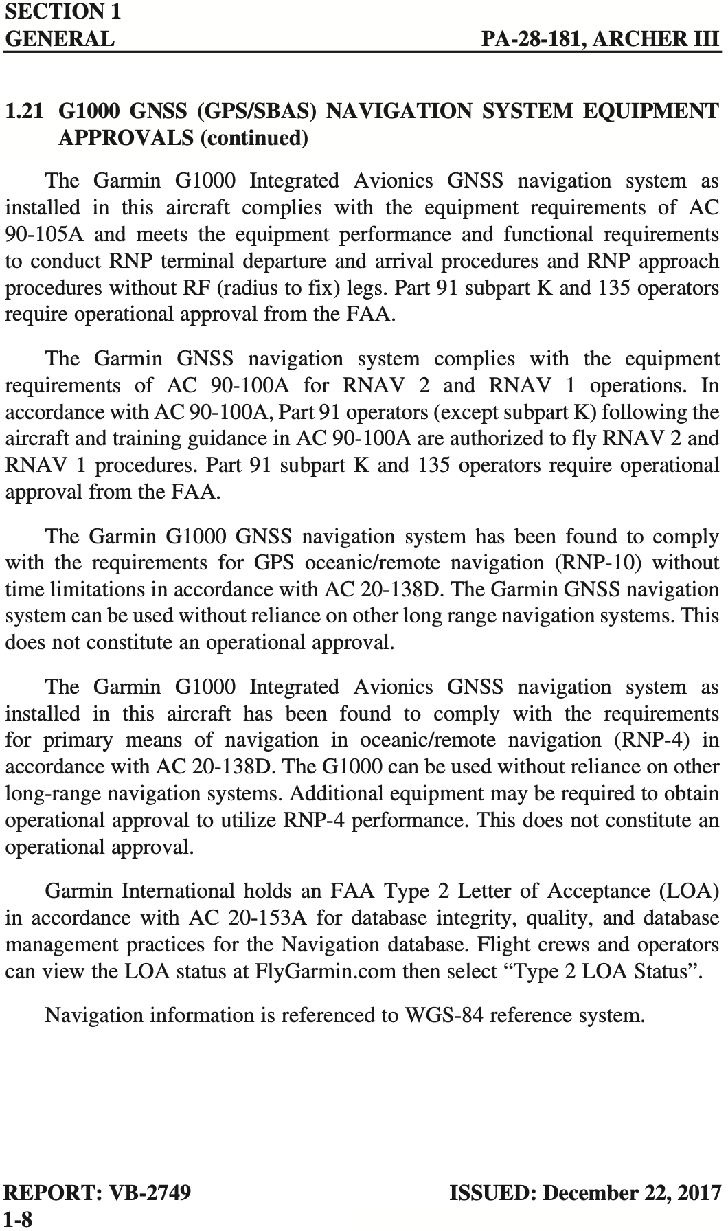
- Determining what requirements a particular aircraft satisfies can be challenging.
- The excerpt from Garmin Performance-Based Navigation Capabilities document indicates some RNP functions for various products
- Some capabilities depend on software versions, so be sure to check carefully what RNP capabilities an aicraft has before flying
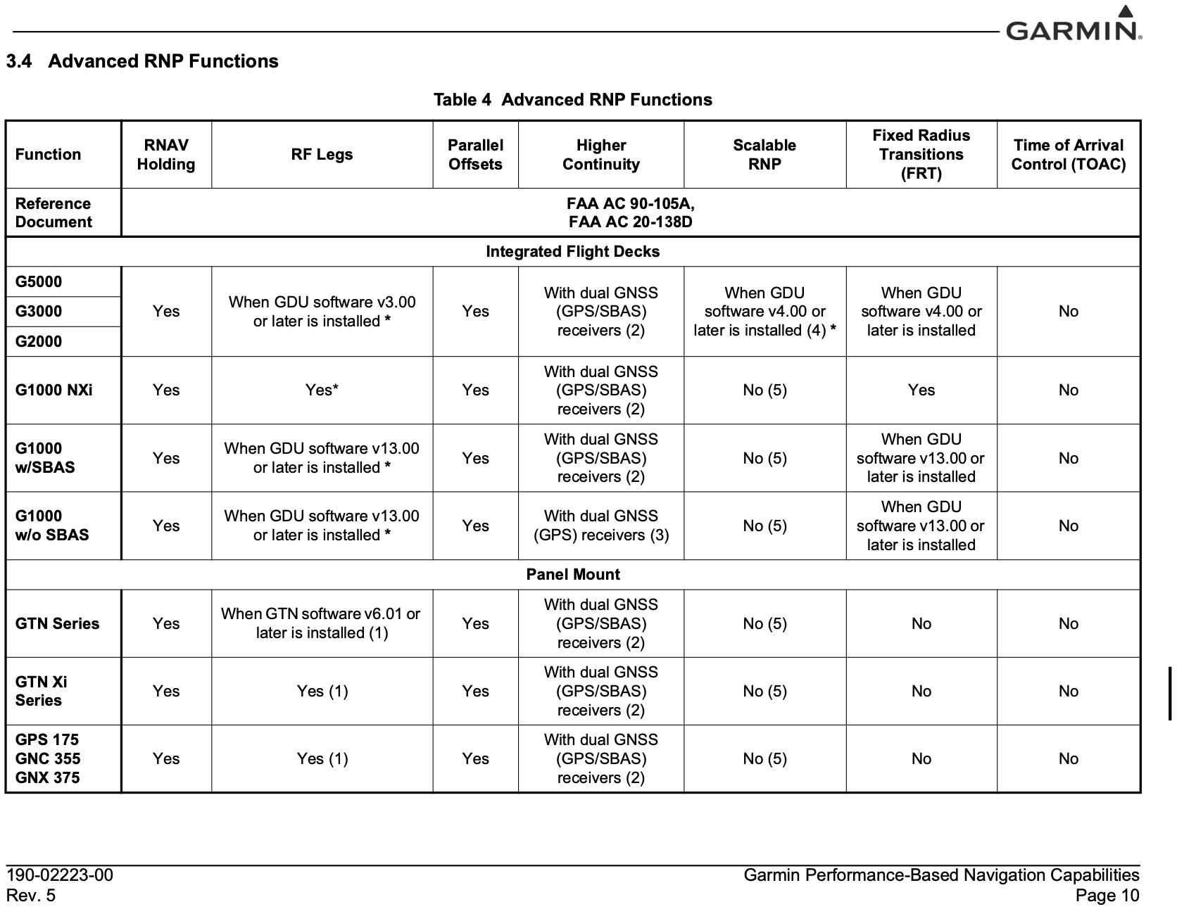
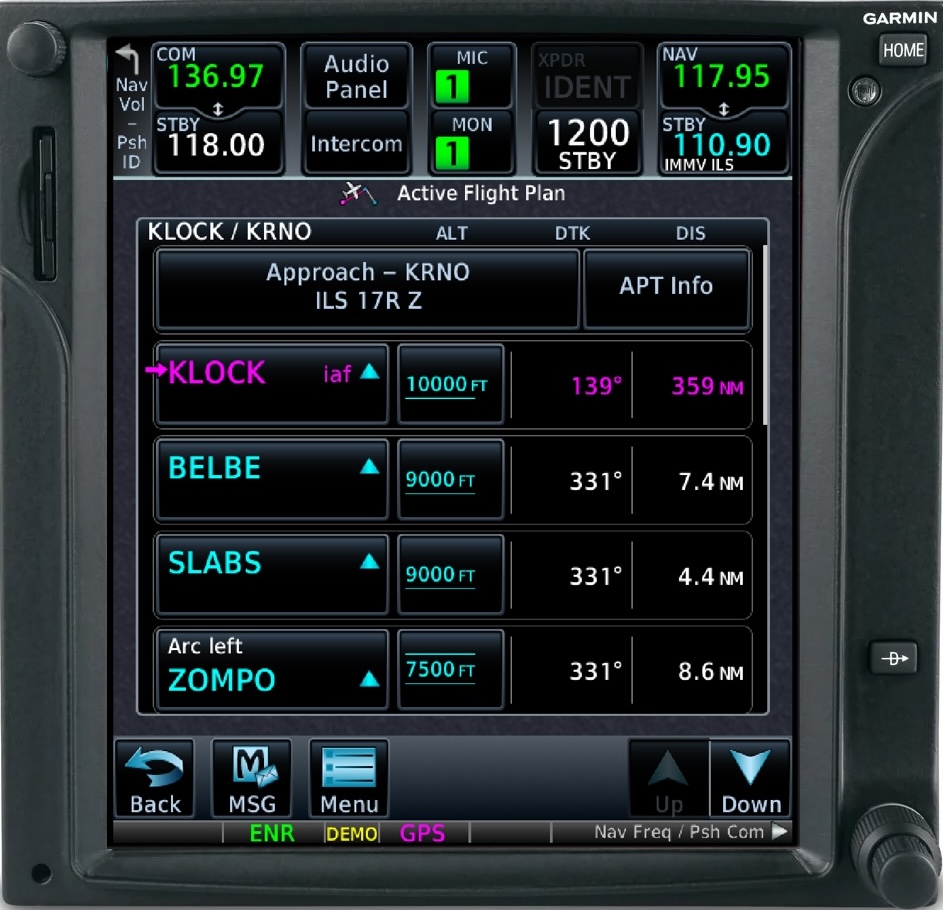
- The Garmin GTN750, which can support RF legs, are indicated in the flight plan view as shown below
RNP AR APCH (AR for Authorization Required)
General aviation operations do not have the authorization required to fly these approaches
In the U.S., RNP AR APCH procedures are titled RNAV (RNP). These approaches have stringent equipage and pilot training standards and require special FAA authorization to fly. Scalability and RF turn capabilities are mandatory in RNP AR APCH eligibility.
Relevant Advisory Circulars
- FAA-AC-91-105A for RNP definitions
- FAA-AC-91-100A for RNAV definitions
- FAA-AC-91-107 for LP and LPV approaches
- FAA-AC-90-101A for RNP procedures with AR
- FAA-AC-20-138D for airworthiness approval
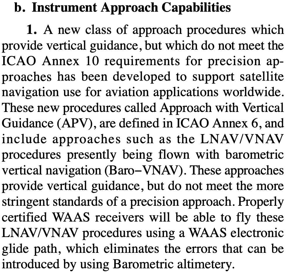
In the past, LNAV/VNAV required a baro-aided altimeter
This has changed to allow appropriately certified WAAS GPS systems to fly LNAV/VNAV approaches, but I don't know exactly when this happened
- One data point is in the 2012 version of the AIM, which states that properly certified WAAS received will be able to fly LNAV/VNAV approaches
- Earlier references indicate the ability to use an appropriate WAAS GPS for LNAV/VNAV approaches
- WAAS was authorized for IFR use in 2003, so certainly before that LNAV/VNAV approaches would have required a baro-aided altimeter
- FAA-AC-90-97 (which was canceled by FAA-AC-91-105A) describes the use of barometric vertical guidance for VNAV

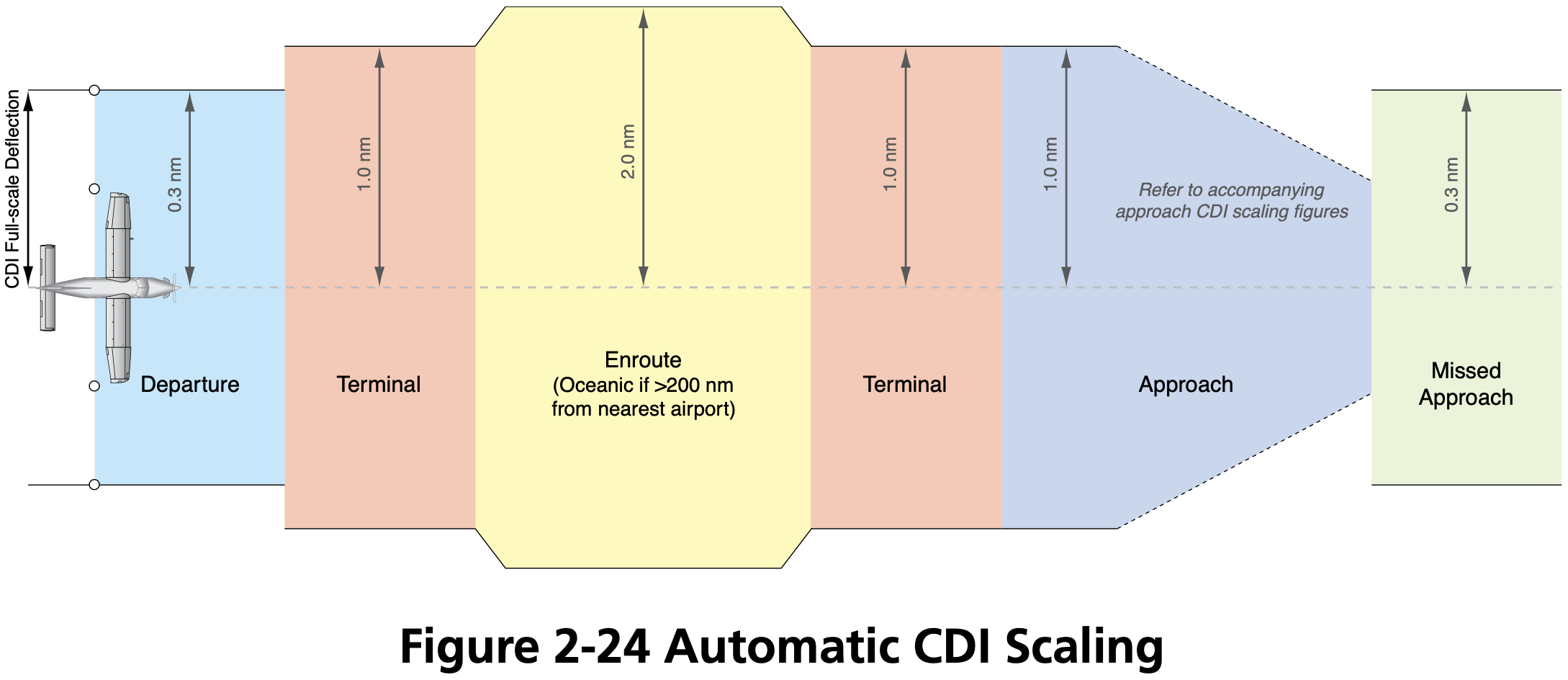
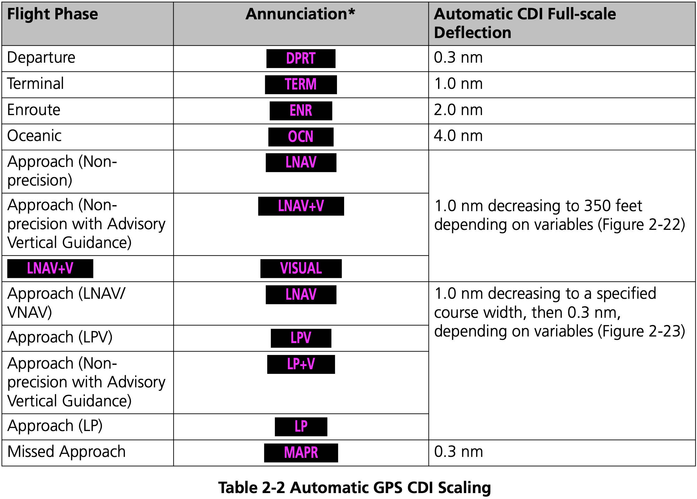
GPS Sensitivity Modes
- Three GPS modes
- Enroute
- More than 30 miles from departure/destination
- 2 nm full-scale deflection
- Terminal
- Within 30 nm of departure/destination
- 1 nm full-scale deflection
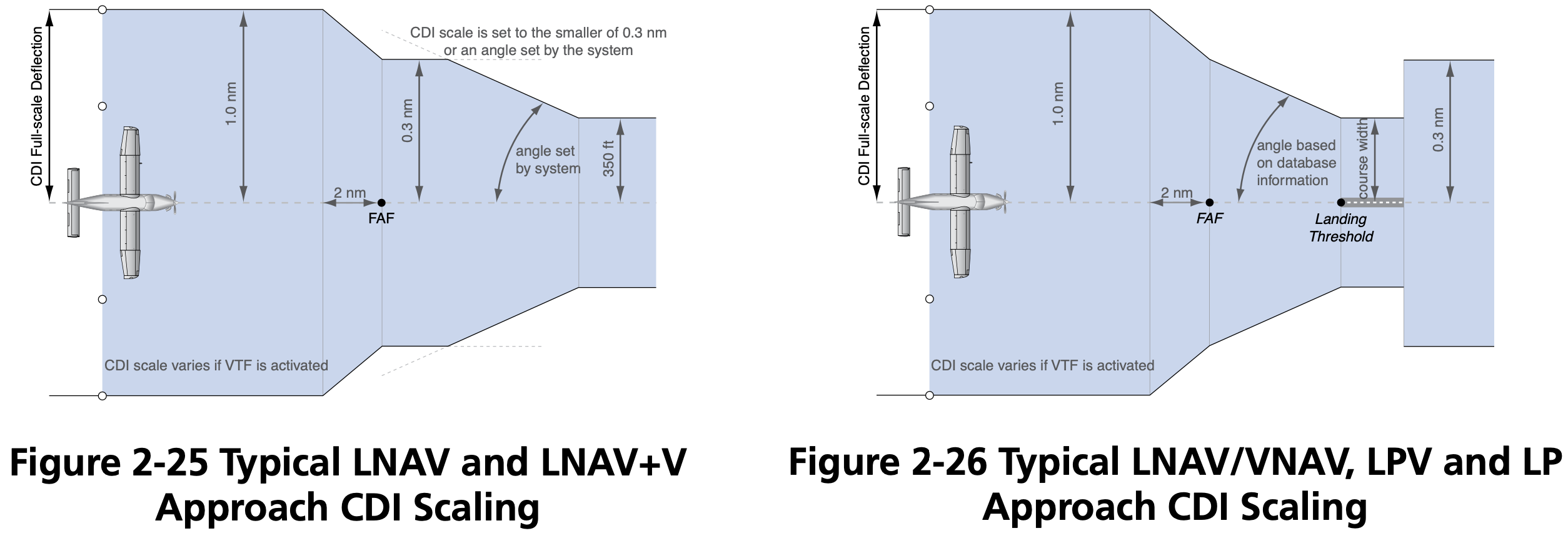
- Approach
- 2 nm before final approach waypoint (FAWP) aka final approach fix (FAF)
- 0.3 nm full-scale deflection
- This approximates the sensitivity of a VOR or Localizer approach if located on the field
- Enroute
GPS Routes
- See AIM 5-3-4
- Q Routes: from 1,200 up to but not including 18,000' MSL
- T Routes: from 18,000 up to FL450
- GPS MEA, e.g.
2900G - Airway width is 4 nm on each side of centerline
- Jet routes
- Start with letter J
- From 18,000 up to FL450
- Have no specified width
Regulations
- Technical Standard Orders (TSO) are the regulations that describe GNSS certification
- Three primary categories
- TSO-C129 / TSO-C196
- Non-WAAS GPS systems
- TSO-C196 seems to be an improved version of TSO-C129
- TSO−C145 / TSO−C146
- WAAS GPS systems
- Uncertified
- VFR-only GPS for advisory / situational awareness
- See AIM Table 1-1-6
- May be used for reference
- May not be used for navigation or approaches
- TSO-C129 / TSO-C196
- Check the AFM or AFM supplement that accompanies the GPS installation that will state whether it is approved for IFR, and under what regulations.
- FAA-AC-20-138D
- Describes certification of GPS
- FAA-AC-20-138D

Non-WAAS GPS
Also called non-augmented GPS
May be used as primary source of navigation if the aircraft has working conventional navigation equipment (e.g. VOR receiver)
Use of a suitable RNAV system as an Alternate Means of Navigation when a VOR, DME, VORTAC, VOR/DME, TACAN, NDB, or compass locator facility including locator outer marker and locator middle marker is operational and the respective aircraft is equipped with operational navigation equipment that is compatible with conventional navaids. For example, if equipped with a suitable RNAV system, a pilot may fly a procedure or route based on operational VOR using that RNAV system without monitoring the VOR.
However, RAIM must be available and working to use GPS as a primary source of navigation
Operators planning to use TSO-C129 equipment as a substitute means of navigation must perform a RAIM prediction during preflight. GPS RAIM availability must be confirmed for the applicable operation and time using current GPS satellite information.
For all RNAV systems, substitute and alternate means of navigation must be discontinued upon loss of integrity (for example, RAIM alert) or unacceptable degradation of system performance.
GPS can be used in lieu of VOR/DME/ADF etc.
- FAA-AC-90-108
- Stated exception is substituting for lateral guidance on final approach course which is discussed in AIM 1-2-3(c) Note 5
- This includes over 24,000 feet requirement to have DME
- FAA-AC-90-108
When selecting an alternate airport for an IFR flight plan, the alternate must have a non-GPS approach that the aircraft is equipped to fly.
For the purposes of flight planning, any required alternate airport must have an available instrument approach procedure that does not require the use of GPS.
This restriction does not apply to RNAV systems using TSO-C145/-C146 WAAS equipment.
However, if the GPS unit has RAIM, and a RAIM check is performed, then an alternate with only a GPS approach can be used, but only if the destination has an approach other than GPS that the aircraft is equipped to fly.
For flight planning purposes, TSO-C129() and TSO-C196() equipped users (GPS users) ... may file based on a GPS-based IAP at either the destination or the alternate airport, but not at both locations.
TIP
Basically, if you are using a non-WAAS GPS, you must make sure RAIM is available and working before using the GPS under IFR.
Receiver autonomous integrity monitoring (RAIM)
RAIM
Receiver autonomous integrity monitoring (RAIM) is a technology for a GPS unit to assess the integrity of GPS signals it receives to make sure they are correct. AIM 1-1-17(a)(3)
RAIM requires a minimum of 5 satellites, or 4 satellites and barometric altimeter input (baro-aiding), to detect an integrity anomaly. Baro-aiding is a method of augmenting the GPS integrity solution by using a non-satellite input source in lieu of the fifth satellite. Some GPS receivers also have a RAIM capability, called fault detection and exclusion (FDE), that excludes a failed satellite from the position solution; GPS receivers capable of FDE require 6 satellites or 5 satellites with baro-aiding.
See also FAA-AC-90-100A U.S Terminal and En Route Area Navigation (RNAV) Operations
Regarding RAIM failure during a GPS approach AIM 1-1-17(b)(5)(g)(6):
If a RAIM failure/status annunciation occurs prior to the final approach waypoint (FAWP), the approach should not be completed since GPS no longer provides the required integrity. The receiver performs a RAIM prediction by 2 NM prior to the FAWP to ensure that RAIM is available as a condition for entering the approach mode. The pilot should ensure the receiver has sequenced from “Armed” to “Approach” prior to the FAWP (normally occurs 2 NM prior). Failure to sequence may be an indication of the detection of a satellite anomaly, failure to arm the receiver (if required), or other problems which preclude flying the approach.
Checking RAIM
There are several ways to check RAIM, the most common by using the SAPT tool online, or using the GPS receivers built-in RAIM prediction functionality
During the pre-flight planning phase RAIM prediction must be performed if TSO-C129() equipment is used to solely satisfy the RNAV and RNP requirement. GPS RAIM availability must be confirmed for the intended route of flight (route and time) using current GPS satellite information.
Operators may satisfy the predictive RAIM requirement through any one of the following methods: ... 2. Operators may use the Service Availability Prediction Tool (SAPT) on the FAA en route and terminal RAIM prediction website; ... 5. Operators may use the receiver's installed RAIM prediction capability
See RAIM Service Availability Prediction Tool (SAPT) Summary Page
Foreflight gives RAIM prediction in the Navlog section.
GPS NOTAMs
- FAA FNS NOTAM Seach
- ForeFlight briefing
Wide-Area Augmentation System (WAAS)
SBAS
Satellite Based Augmentation System (SBAS) augments GNSS with additional ground stations/enhanced information transmitted from satellites for improved accuracy and reliability.
WAAS
Wide-Area Augmentation System (WAAS) is the US implementation of SBAS.
Other SBAS implementations include
- EGNOS - Europe
- MSAS - Japan
- SDCM - Russia
- GAGAN - India
WAAS accuracy can achieve position accuracy of approximately 25 ft 95% of the time.
Enables certain GPS approaches to be performed to lower minimums than otherwise allowed with a non-WAAS GPS (e.g. LPV)
WAAS works by using ground stations at known locations to determine their GPS-measured location
Based on the difference between their known location and measured location a correction message is sent up to some WAAS satellites in geostationary orbit
These corrections are then sent from the WAAS satellites to WAAS-capable GPS receivers
- There are currently 3 such WAAS satellites
If WAAS is working then do not need to be concerned with RAIM
If TSO-C145/C146 equipment is used to satisfy the RNAV and RNP requirement, the pilot/operator need not perform the prediction if WAAS coverage is confirmed to be available along the entire route of flight.
In the Piper Archer POH (VB-2749) page 2-8:
In areas where GPS WAAS SBAS coverage is not available, the pilot must verify RAIM availability.
Regarding checking WAAS in the Piper Archer POH (VB-2749) page 2-8:
For information on using the WFDE Prediction Program, refer to Garmin WAAS FDE Prediction Program, part number 190-00643, 'WFDE Prediction Program Instructions'.
May be used as primary source of navigation without any other equipment requirements imposed on the aircraft
Unlike TSO-C129 avionics, which were certified as a supplement to other means of navigation, WAAS avionics are evaluated without reliance on other navigation systems. As such, installation of WAAS avionics does not require the aircraft to have other equipment appropriate to the route to be flown.
When using WAAS, alternate airport need only have a GPS approach
For the purposes of flight planning, any required alternate airport must have an available instrument approach procedure that does not require the use of GPS. ... This restriction does not apply to RNAV systems using TSO-C145/-C146 WAAS equipment.
Pilots with WAAS receivers may flight plan to use any instrument approach procedure authorized for use with their WAAS avionics as the planned approach at a required alternate, with the following restrictions. When using WAAS at an alternate airport, flight planning must be based on flying the RNAV (GPS) LNAV or circling minima line, or minima on a GPS approach procedure, or conventional approach procedure with “or GPS” in the title.
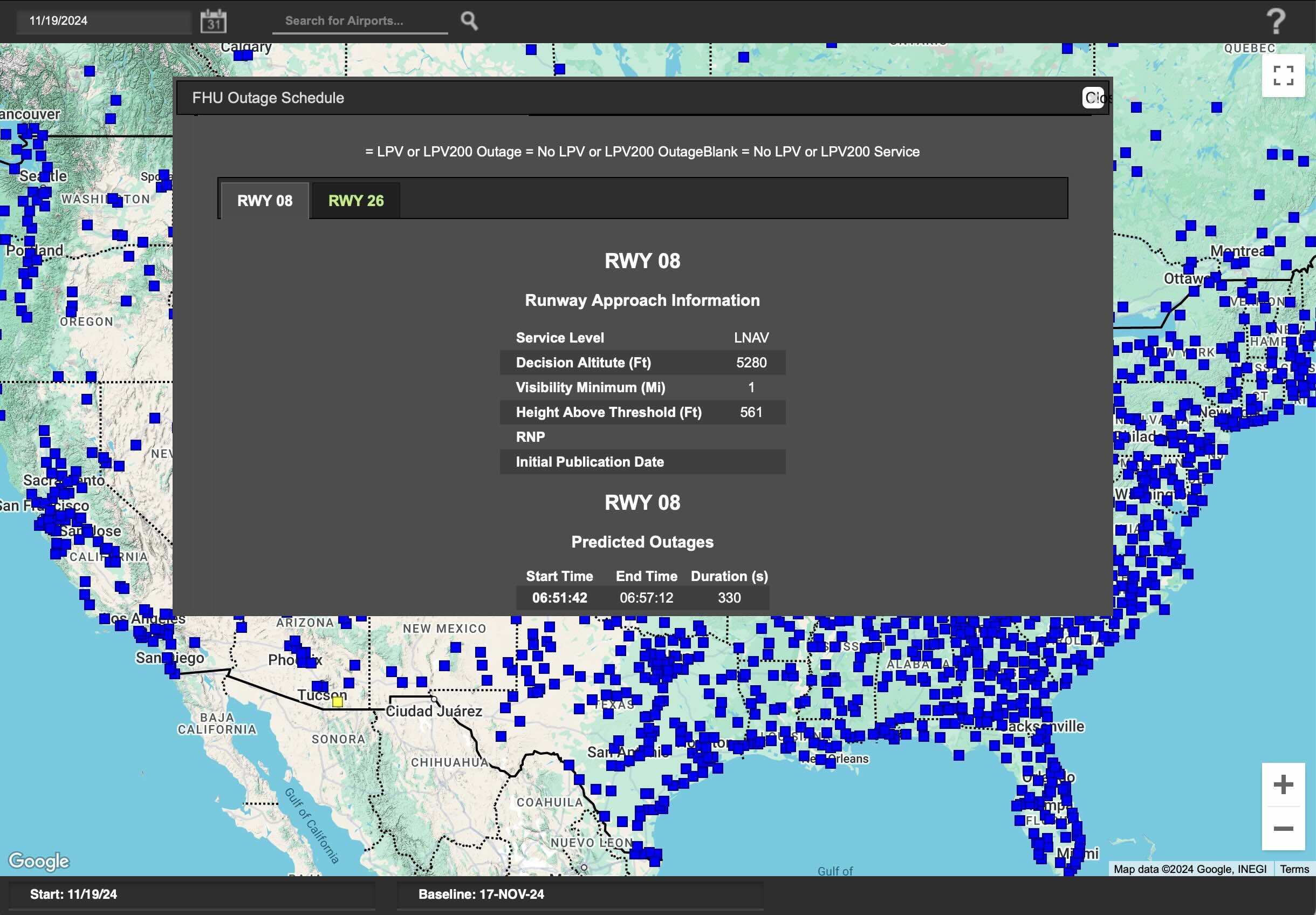
Checking WAAS Availability
- The William J. Hughes Technical Center WAAS Test Team website seems to be the best resource for checking WAAS availability
- The Airport Schedules application seems to be the easiest way to determine WAAS availability
Determining GPS Receiver Capabilities
Check AFM/POH
- See, for example on a Cessna 172S G1000, the POH Section 2 - G1000 LIMITATIONS - GPS-WAAS for more info.
- In the Garmin G1000 NXi Pilot's Guide for the PA-28-181 Archer see the System Overview section
Check aircraft receiver
In the Garmin G1000 NXi Pilot's Guide for the PA-28-181 Archer it describes the PRN (pseudo-random noise, the unique ID identifying the satellite) and signal strength bars
As the GPS receiver locks onto satellites, a signal strength bar is displayed for each satellite in view, with the appropriate satellite PRN number (01-32 or 120-138 for WAAS) below each bar.
The signal strength bars are described on page 20, but a solid green bar means the satellite is being used
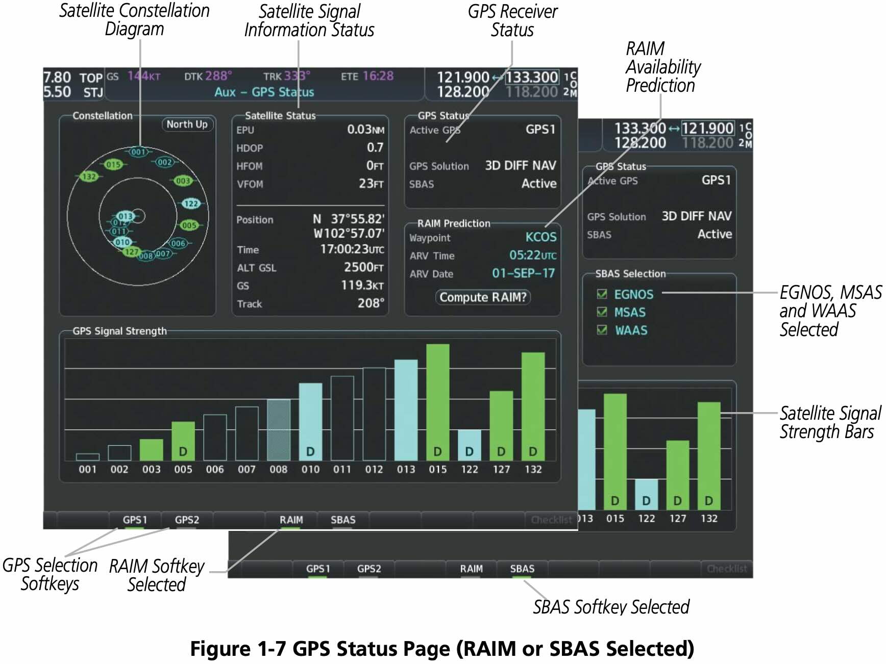
- WAAS satellite PRN 138 was decommissioned in May 2022 and replaced by PRN 135
Using GPS During IFR Operations
- Verify database is current
- See the exception in AIM Table 1-1-6 that allows flying with an expired GPS database
- Verifying approaches haven't changed or been amended
- Verifying route hasn't changed
- See the exception in AIM Table 1-1-6 that allows flying with an expired GPS database
- Check RAIM or WAAS
Using GPS for Non-GPS Approaches
GPS can be used in lieu of a VOR for a VOR approach if the underlying NAVAID is monitored for final approach segment coarse alignment
AIM 1-2-3(c) Note 5
Use of a suitable RNAV system as a means to navigate on the final approach segment of an instrument approach procedure based on a VOR, TACAN or NDB signal, is allowable. The underlying NAVAID must be operational and the NAVAID monitored for final segment course alignment.
If a DME fix on a Localizer approach isn't in the GPS database you may only define that fix using GPS distance from the localizer antenna
TIP
To satisfy the requirement that the NAVAID underlying frequency be monitored on the final approach course, tune the VOR use the bearing pointers, and ensure they align with guidance provided by GPS.
GPS Failures
- On the G1000, the GPS flight phase (e.g.
ENR,TERM,LPV) is shown on the HSI to the right of the CDI - Normally this text is magenta
- If cautionary conditions exist this text will be in amber
- the
LOI(Loss of Integrity Monitoring) indication appears to the right of the HSI when GPS integrity is insufficient for the current phase of flight
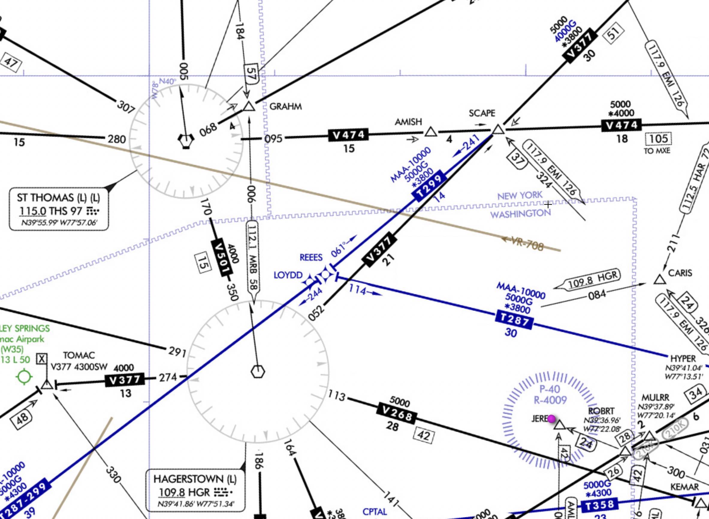
IFR En Route Charts
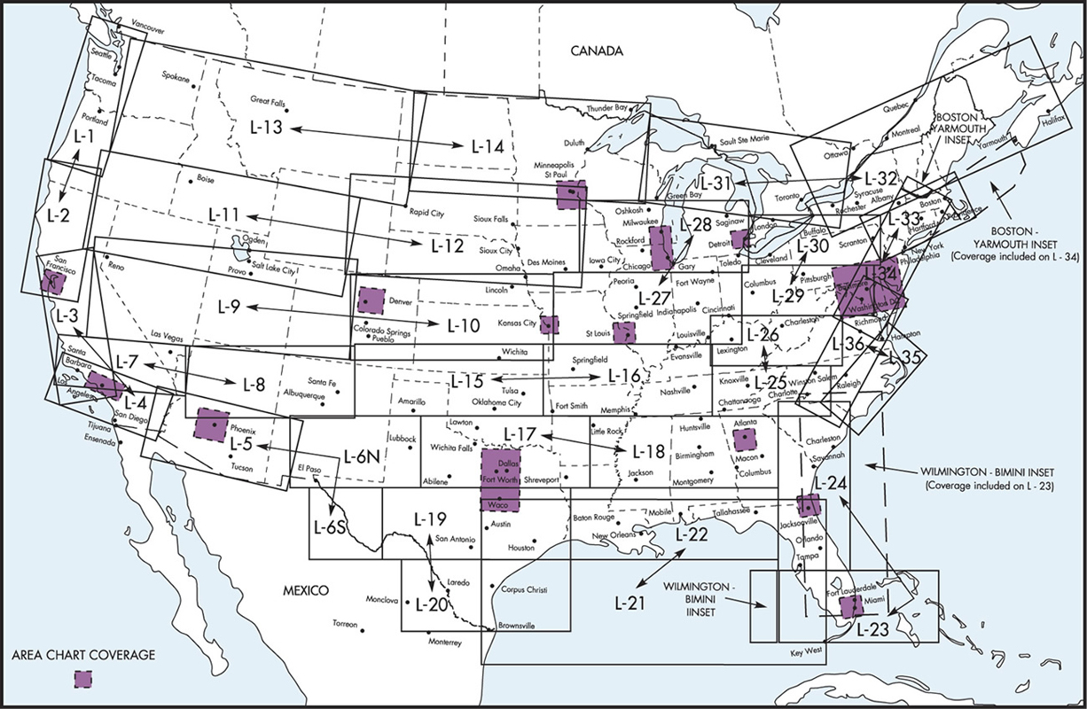
- See the FAA document Aeronautical Chart Users' Guide IFR Enroute Charts for descriptions of terms and symbols used on IFR enroute charts.
- Updated every 56 days
- IFR low chart is used under 18,000 ft.
- Victor airways - from 1200 AGL up to but not including FL 180
- T-Routes - like victor airways but for GPS navigation on IFR low charts
- Can use T-Routes with a suitable GPS
- On IFR high charts these are Q-Routes
- AIP ENR 3.3 Area Navigation (RNAV) Routes
- AIM Chapter 1 Section 2 Performance-Based Navigation (PBN) and Area Navigation (RNAV)
- Magnetic Reference Bearing (MRB)
- Published magnetic bearing between two waypoints on an RNAV/GPS/GNSS route
- Used to enhance situational awareness by associating magnetic course with GPS leg to check against compass
- Blue or green airports on IFR chart have instrument approach procedure (IAP) and/or radar minima, where this is related to ASR or PAR (radar) approaches
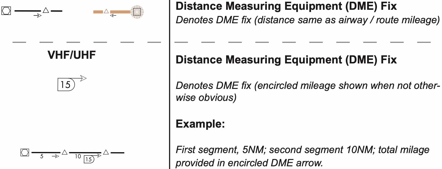
DME Distance Arrows on Low Enroute Chart
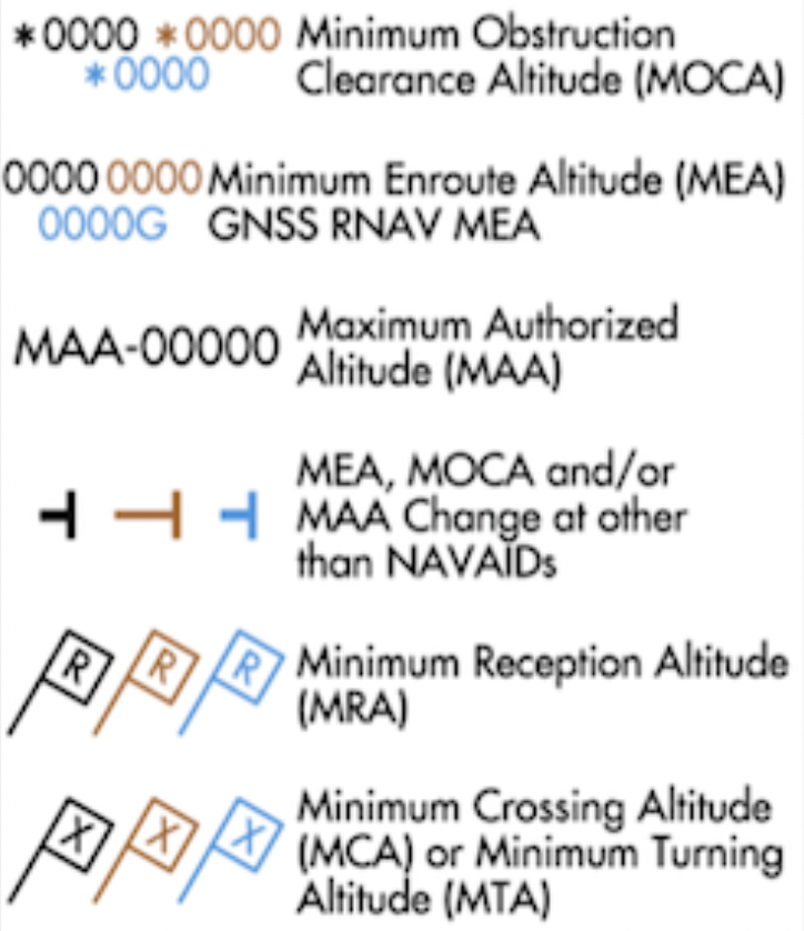

IFR Altitudes
- Minimum Enroute Altitude (MEA)
- Ensures acceptable nav signal coverage and meets obstacle clearance requirements
- 1,000' in non-mountainous areas, 2,000' in mountainous areas
- Ensures radio communication
- Does not guarantee radar coverage
- Ensures acceptable nav signal coverage and meets obstacle clearance requirements
- Minimum Obstruction Clearance Altitude (MOCA)
- Meets obstacle clearance requirements
- Ensure acceptable navigation signal only within 22 nm of VOR
- Only published when it is lower than the MEA
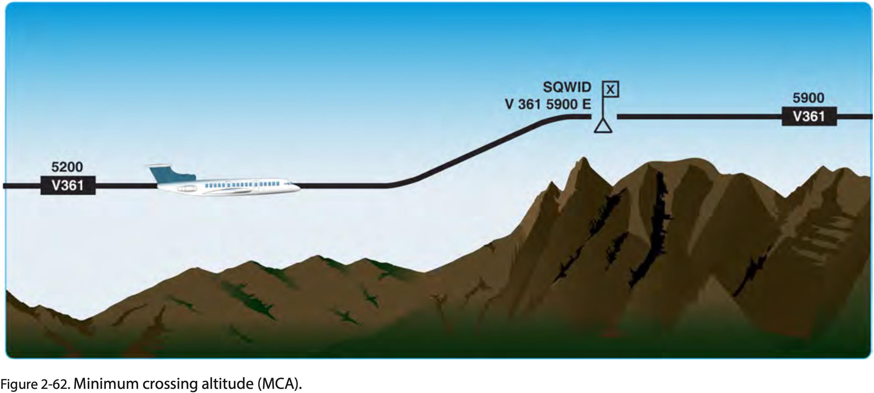
- Minimum Crossing Altitude (MCA)
- Lowest altitude at crossing point when going to a higher MEA, indicated on chart by flag with x.
- Minimum Reception Altitude (MRA)
- Lowest altitude at which an intersection can be determined.
- Maximum Authorized Altitude (MAA)
- Maximum altitude that ensures adequate reception of navigation aid signals.
- Off-Route Obstruction Clearance Altitude (OROCA)
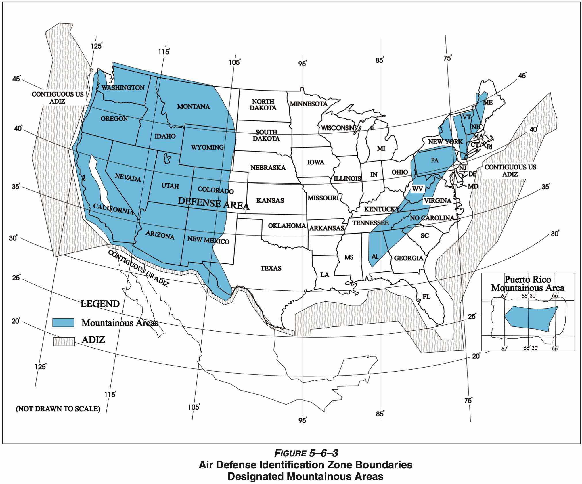
- OROCA is computed just as the Maximum Elevation Figure (MEF) found on Visual Flight Rule (VFR) Charts except that it provides an additional vertical buffer of 1,000 feet in designated non-mountainous areas and a 2,000 foot vertical buffer in designated mountainous areas within the United States.
- Does not guarantee nav aid or radio reception.
- Minimum Turning Altitude (MTA)
- Minimum turning altitude (MTA) is a charted altitude providing vertical and lateral obstruction clearance based on turn criteria over certain fixes, NAVAIDs, waypoints, and on charted route segments.
- Minimum Vectoring Altitude (MVA)
- This altitude is not published, but something ATC has (and can be requested if you want to know)
- Lowest altitude a controller can issue a clearance for
- For example, if would like vectors for a visual approach, this is the lowest altitude they can clear you too, so if it's not below the ceiling won't work for visual approach
- Provides 1,000 feet of clearance above the highest obstacle in non-mountainous areas and 2,000 feet above the highest obstacle in designated mountainous areas
- Maximum Elevation Figure (MEF)
- On VFR charts.
- Minimum IFR Altitude (MIA)
- In designated mountainous areas, 2,000 feet above the highest obstacle within a horizontal distance of 4 NM from the course to be flown
- Other than mountainous areas, 1,000 feet above the highest obstacle within a horizontal distance of 4 NM from the course to be flown
- Or as otherwise authorized by the Administrator or assigned by ATC
- Mountainous areas are defined in 14 §CFR 95.13 Eastern United States Mountainous Area and other parts within 14 §CFR 95 Subpart B Designated Mountainous Areas
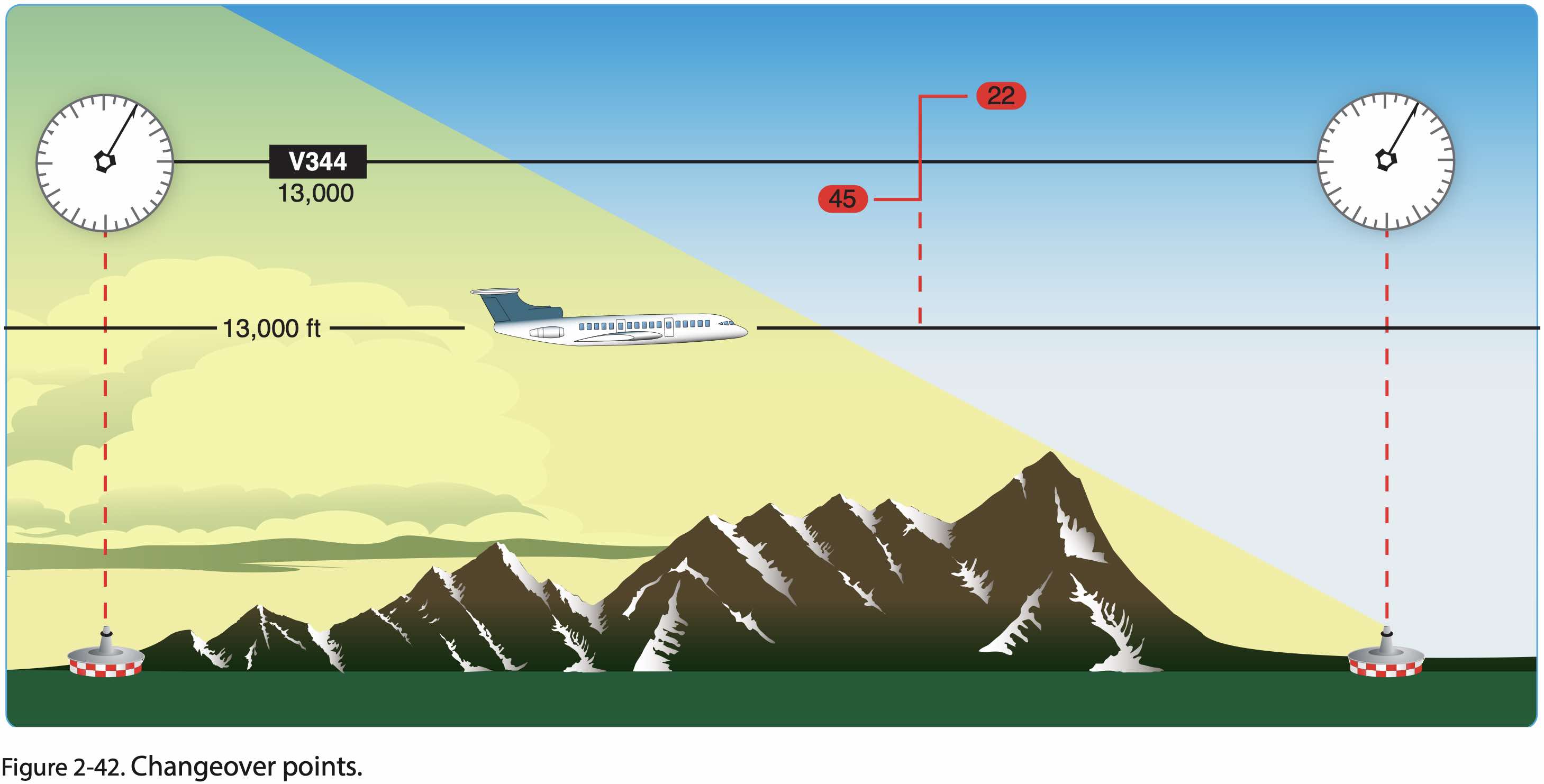
- Changeover point
- When to change from one navaid to another
Mandatory Reporting Points
- Required reports (MARVELOUS VFR C500)
- M - Missed approach
- A - Airspeed
- +/- 10 kts or 5% of filed TAS (whichever greater)
- ATC basically wants to know if we are making a deliberate power change
- R - Reaching a holding fix
- Time and altitude
- Crossing the holding fix outbound as part of our entry procedure
- V - VFR on-top altitude changes
- E - ETA change
- Of more than +/- 2 minutes
- In non-radar environment
- L - Leaving a holding fix
- O - Outer marker inbound
- In non-radar environment
- Outer marker indicates final approach fix for non-precision approach
- U - Unforecast weather
- Especially icing, turbulence, wind
- S - Safety of flight
- V - Vacating an altitude or flight level
- F - FAF inbound
- In non-radar environment
- R - Radio or navigation failure
- Report loss of any equipment which may impair safety and/or ability to operate under IFR
- AIM 5-3-3 a.1 (h)
- 14 CFR §91.187
- C - Compulsory reporting points
- In non-radar environment
- 500 - Failure to maintain at least 500 FPM climb or descent
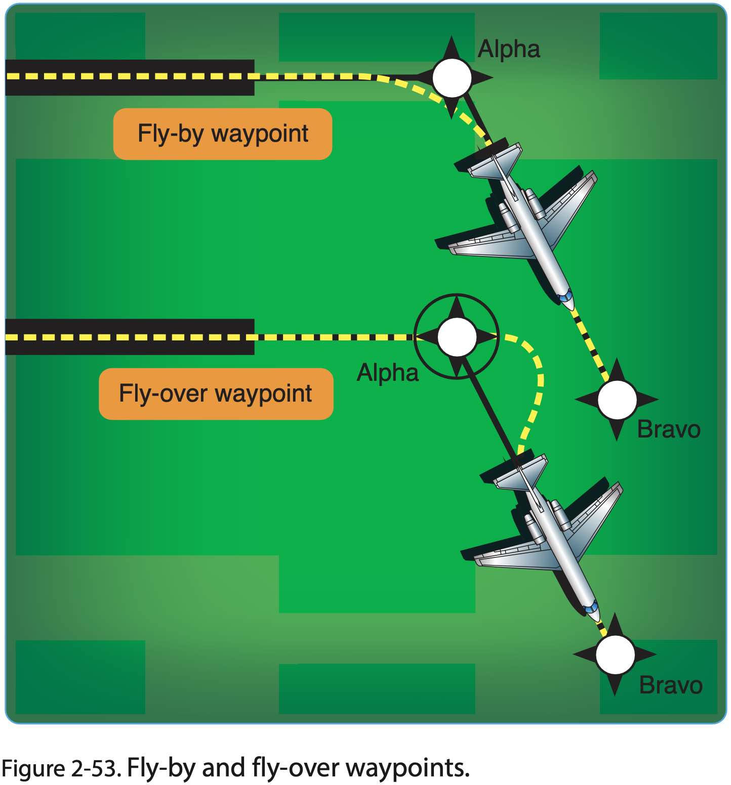
Waypoints
- This is applicable to other portions of IFR flight too, e.g. departure, arrival, and approach
- Flyover vs. flyby waypoints
En Route Weather
- Onboard Weather Radar
- Most up-to-date weather information available
- May be used for "tactical" weather avoidance
- Good supplement to existing weather sources
- Has limitations like blind splot where distance stuff can be blocked by near stuff
- XM lightning
- Lightning strikes sensed by ground stations
- Lightning can't hide from ground stations
- Broadcast to plane via satellite
- NEXRAD
- Ground-based radar information broadcast to planes via satellite
- Information may be 15 minutes or more old
- NEXRAD and ADS-B weather both come from NWS
- ADS-B
- Flight Information Services-Broadcast (FIS-B)
- Information sent directly to planes from ground stations
- Usually no more than 5 minutes old
- Flight service
- Nationwide on 122.2
- Available over most VORs
- Hazardous Inflight Weather Advisory Service (HIWAS)
- Continuous broadcast service over selected VORs of Inflight Weather Advisories; i.e. SIGMETs, CONVECTIVE SIGMETs, AIRMETs, Severe Weather Forecast Alerts (AWWs), and Center Weather Advisories (CWAs).
- Discontinued in 2020
Abnormal Procedures and Emergencies
Communication Failure Under IFR
- If the radio fails while VFR, fly VFR and land as soon as practicable
- Squawk 7600
- Unless you decide to declare an emergency, then squawk 7700
- The following rules determine the route and altitude that should be be flown should a radio failure happen in flight and the flight is continued
- If flight needs to be continued IFR after losing communications, the following route should be flown (AVEF)
- A - Assigned
- In last ATC clearance
- V - Vectored
- E - Expected
- From last ATC communication
- F - Filed
- In flight plan
- A - Assigned
- If flight needs to be continued IFR after losing communications, the highest of the following altitude should be flown (MEA) for each route segment
- M - Minimum altitude for IFR operations
- E - Expected
- From last ATC communication
- A - Assigned
- In last ATC clearance
- See 14 CFR §91.185 IFR operations: Two-way radio communications failure
- If radio failure happens and clearance limit is the fix from which approach begins, start descent and approach as close as possible to EFC time, or to arrive at estimated arrival time from flight plan (or amended enroute.)
- If clearance limit is not a fix from which approach begins, leave the clearance limit at EFC time or arrival at the fix if no EFC time, and start approach to begin as close as possible to estimated time of arrival from flight plan (or amended enroute.)
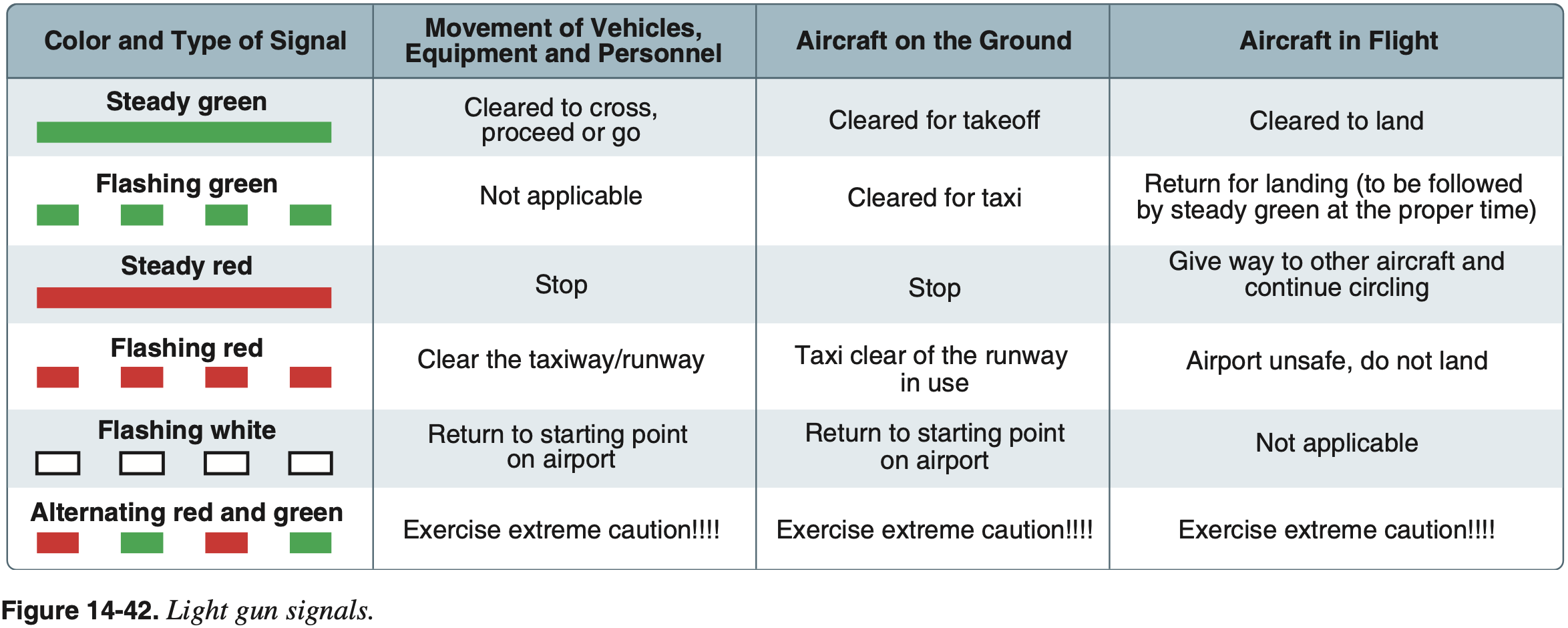
Light Gun Signals
Troubleshooting
- Check frequency
- Check volume
- Try previous frequency
- Try other radio
- Check for TX/RX
- Try other headphone jacks
- Try other PTT
- Try handheld mic
- Try overhead speaker
- Try EMG
- Try other headset
- Otherwise go 7600
References
- FAA-H-8083-15B Instrument Flying Handbook
- Chapter 11: Emergency Operations
- Page 11-8: Communication/Navigation System Malfunction
- Chapter 11: Emergency Operations
Equipment Failure Under IFR
- When IFR, report any navigational, approach, or communication equipment failures that occur in flight
- 14 CFR §91.187 Operation under IFR in controlled airspace: Malfunction reports
- Aircraft identification
- Equipment affected
- Degree to which the capability of the pilot to operate under IFR in the ATC system is impaired
- Nature and extent of assistance desired from ATC
- 14 CFR §91.187 Operation under IFR in controlled airspace: Malfunction reports
- Discussion around ADM should failures occur
- Equipment malfunction under IFR AIM 5-3-3
- Report loss of any equipment which may impair safety and/or ability to operate under IFR
Holding Procedures
Holding Overview
Hold Procedure
A predetermined maneuver which keeps aircraft within a specified airspace while awaiting further clearance from air traffic control.
- See FAA Pilot/Controller Glossary: Hold Procedure
- The following are some of the reasons for holds
- Await further clearance
- Upon reaching the clearance limit (C in CRAFT) before further clearance has been received
- For example to allow separation with other traffic
- Reverse course on an approach
- Buy time to get configured for an approach
- Lose altitude as needed before beginning an approach
- Wait for hazardous weather or low ceilings or bad visibility to pass
- Allow traffic congestion to clear
- Wait for airport or runway closures to clear up
- Equipment outages
- Providing more time when handling abnormal situations and emergencies
- As part of a missed approach procedure as next steps are determined
- Await further clearance
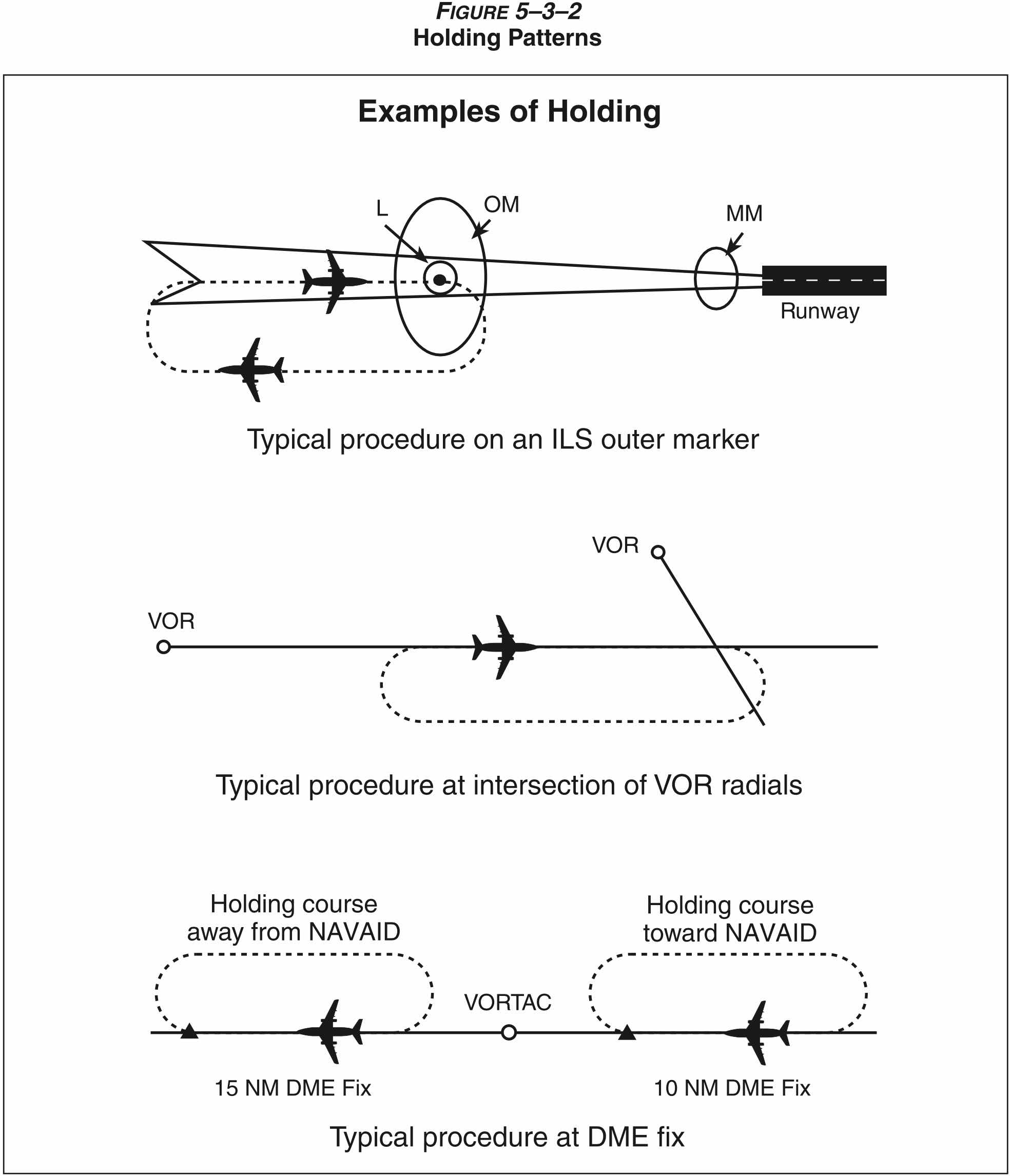
Structure of a Hold
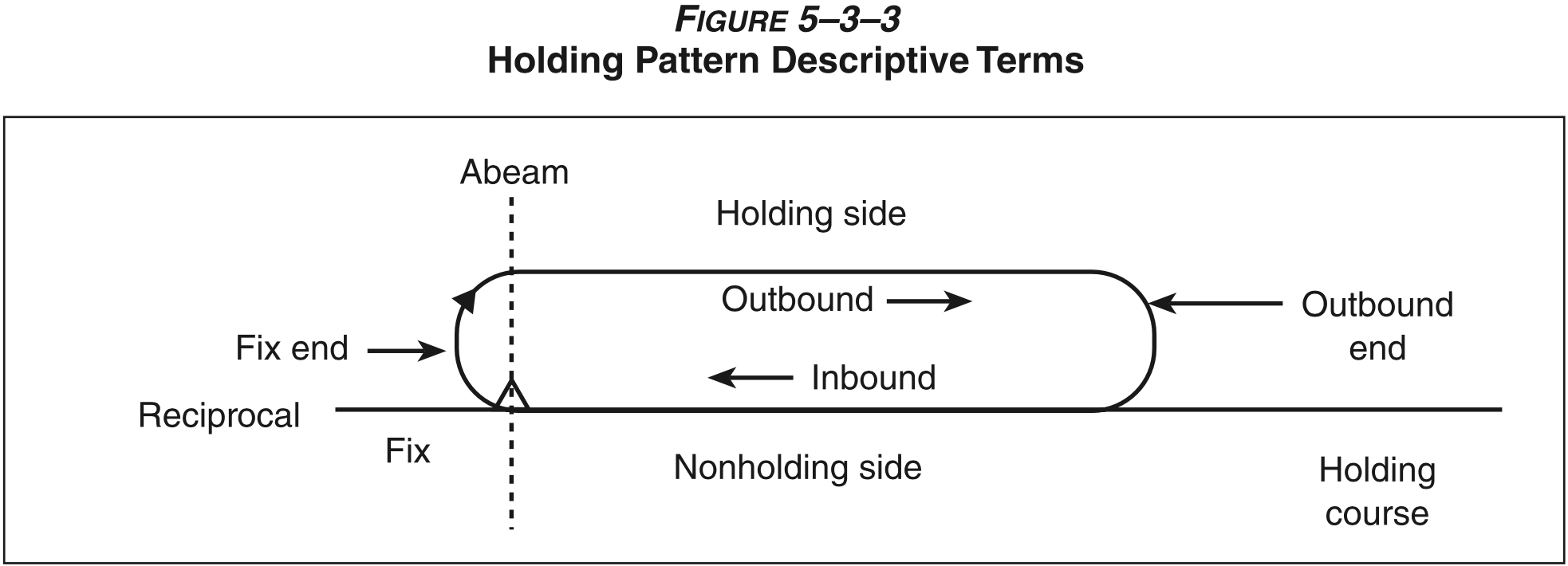
- The figure above shows the basic structure of a hold, defined by four things
- Holding fix
- Inbound leg
- Size
- Direction of turns
- The holding fix can be defined by
- The location of a VOR
- The intersection of VOR radials
- A VOR radial and DME
- A GPS waypoint
- And just about any other way to define a location
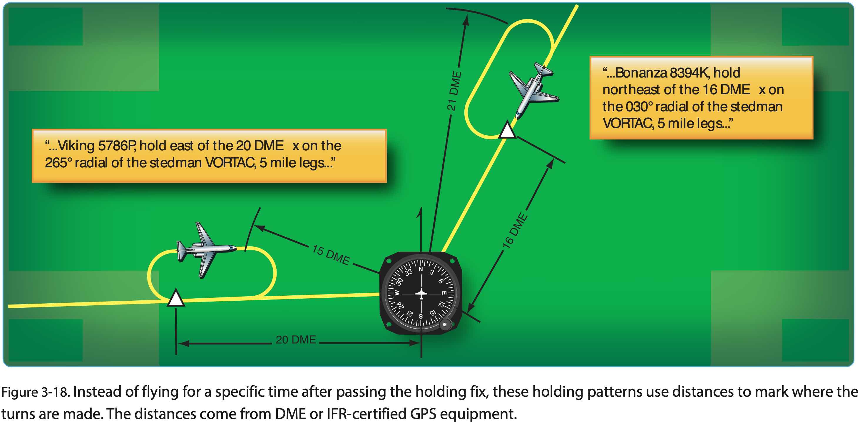
- Holds can be defined by time or distance
- In timed holds, it is the inbound leg that is the reference
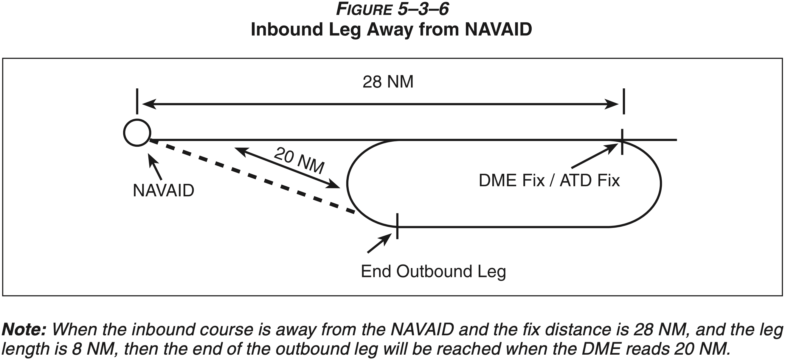
- In the case of distance holds, it is the outbound leg
- Standard hold direction is right turns
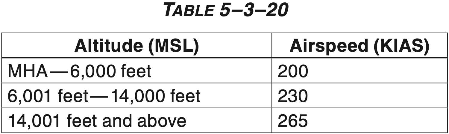
- In the case of timed holds, the standard hold time depends on altitude
- 1 minute inbound leg at or below 14,000 ft MSL
- 1.5 minute inbound leg above 14,000 ft MSL
- To remember this 1.5 minutes comes into play at 15,000 ft MSL
- Airlines typically ask for 10 mile legs
- It is not a bad idea to ask for 5 mile legs to reduce workload
- Never hurts to ask ATC to slow down as soon as holding instructions are given when approaching the holding fix
- Can save some more fuel
- And may be the case that by the time you arrive at the holding fix you don't even need to hold anymore
- Bank angle in hold
- Use 15° bank which is approximately standard rate
- When given a hold ATC should give EFC time, but if they don't it's a good idea to ask for it so in case comms are lost, we know when to leave the holding fix
- Can hold at a GPS fix using OBS mode
- OBS suspends GPS from sequencing to the next waypoint and allows us to dial in a radial
- Note: the outbound leg could be greater or less than the 1 minute inbound leg due to wind
- More on wind correction below
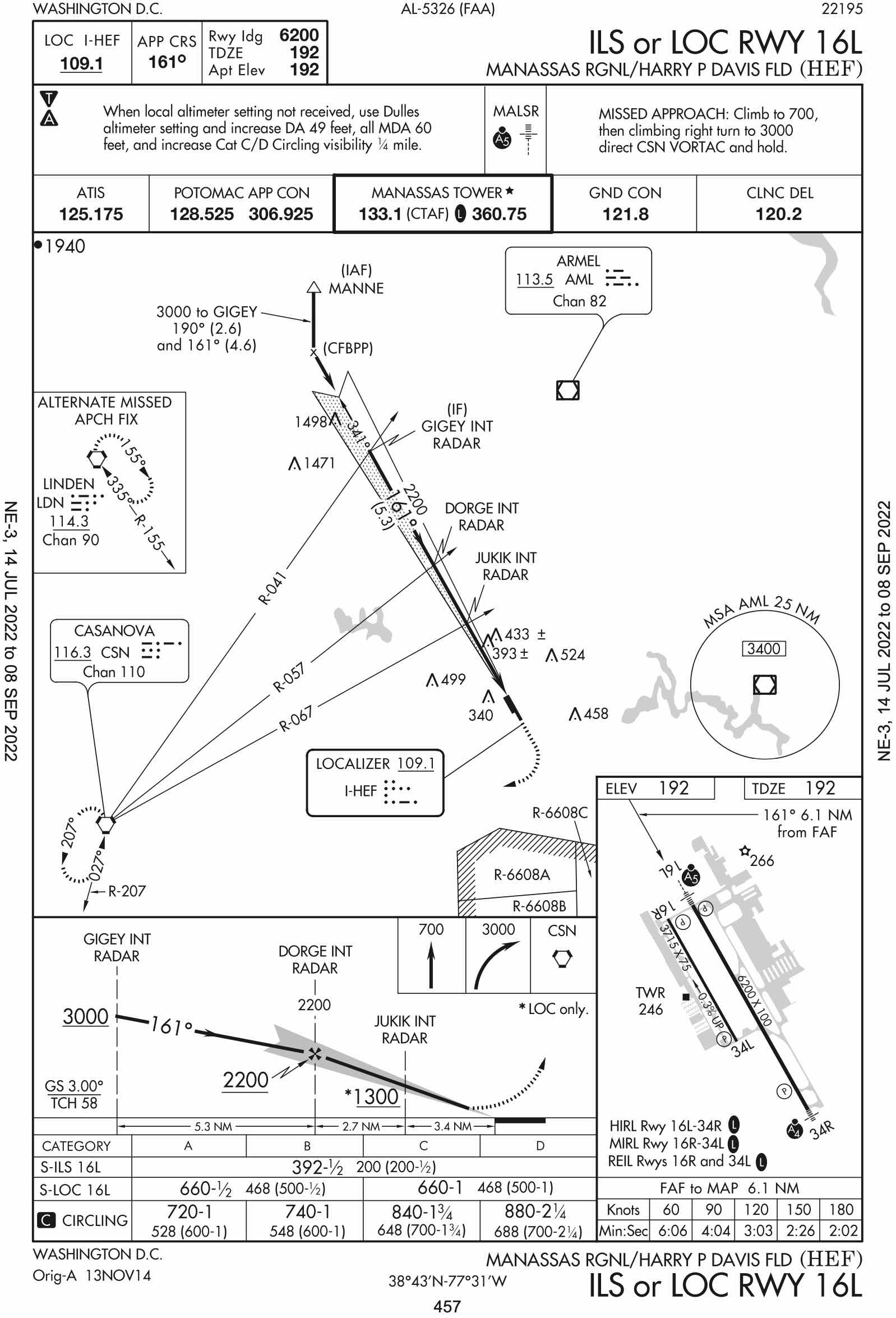
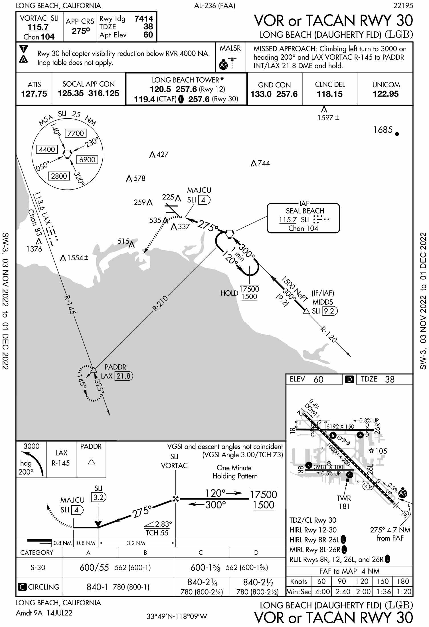
Example of a Hold on an Instrument Approach Plate
Holding Entry
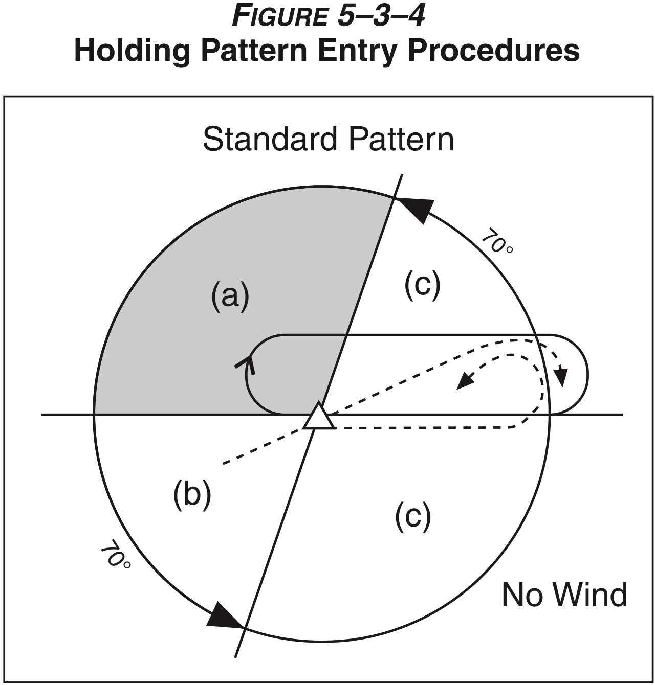
- There are three standard holding entry procedures that are used depending on the relative direction from which you are approaching the holding fix
- Direct Entry
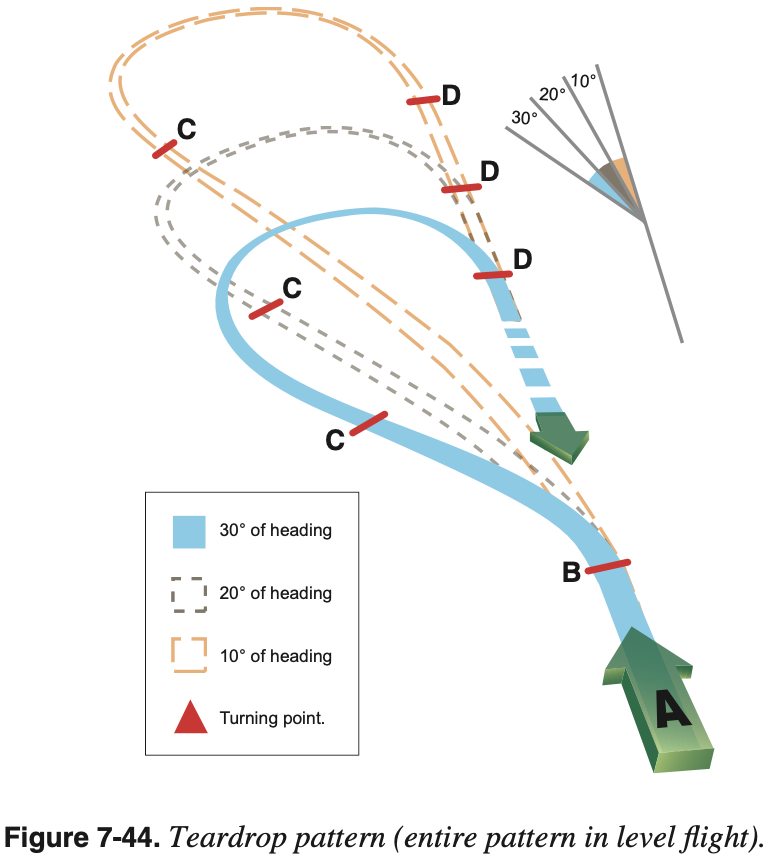
- Teardrop Entry
- Use 30° angle for 1 minute legs
- Use 15° angle for 4 nm legs
- Closer to 6° angle for 10 nm legs
- Parallel Entry
- Use 45° intercept angle
- Note: Parallel hold entry does not fly the inbound leg outbound, it parallels it only
- In fact the AIM expressly says to fly over the holding fix then turn to a heading to parallel the holding course outbound on the nonholding side
- This means after crossing the holding fix use the pink diamond to track the outbound course, but again it will be parallel
- While we should always strive to execute the proper procedure to enter into the hold, ATC doesn't really care
- The most important thing is to remain in the protected area
- In flight this means don't get bogged down with single degree precision determinations of hold entries, or re-determining your entry if your bearing relative to the fix changes slightly
- Rather, make a reasonable calculation of the hold entry and the necessary heading after crossing the fix, and execute this entry
TIP
Determine the hold entry as early as practicable when expecting to hold. For example when briefing an approach you can determine and brief the expected entry to the hold on the missed approach procedure.
Details
There are details regarding holding both in AIM 5-3-8 and AIM 5-4-9 both have information on holds.
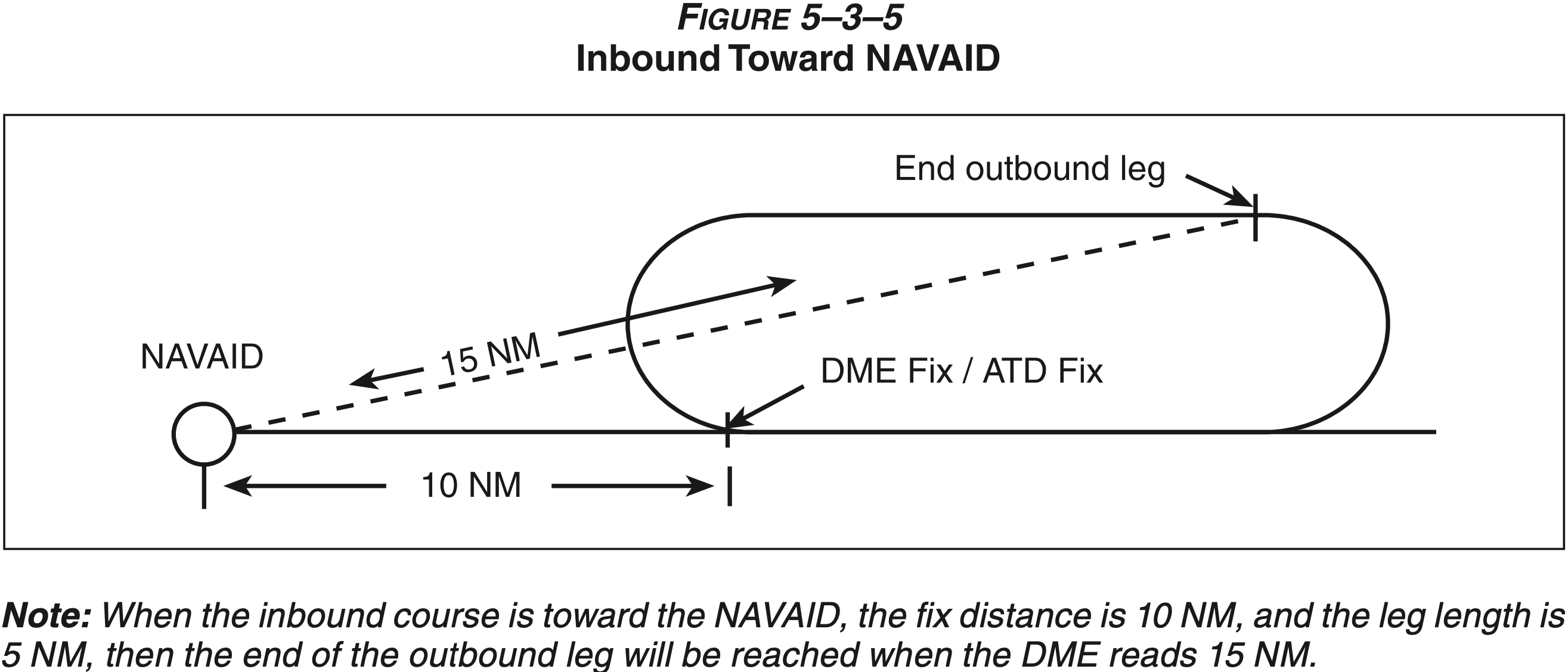
AIM 5-3-8(j)(5) states the following with respect to hold entries for DME holds:
DME/GPS holding is subject to the same entry and holding procedures except that distances (nautical miles) are used in lieu of time values.
This is the same guidance as in FAA-H-8083-15B Instrument Flying Handbook page 10-13.
AIM 5-3-8(j)(4) states:
The initial outbound leg should be flown for 1 minute or 1 1/2 minutes (appropriate to altitude). Timing for subsequent outbound legs should be adjusted, as necessary, to achieve proper inbound leg time. Pilots may use any navigational means available; i.e., DME, RNAV, etc., to ensure the appropriate inbound leg times.
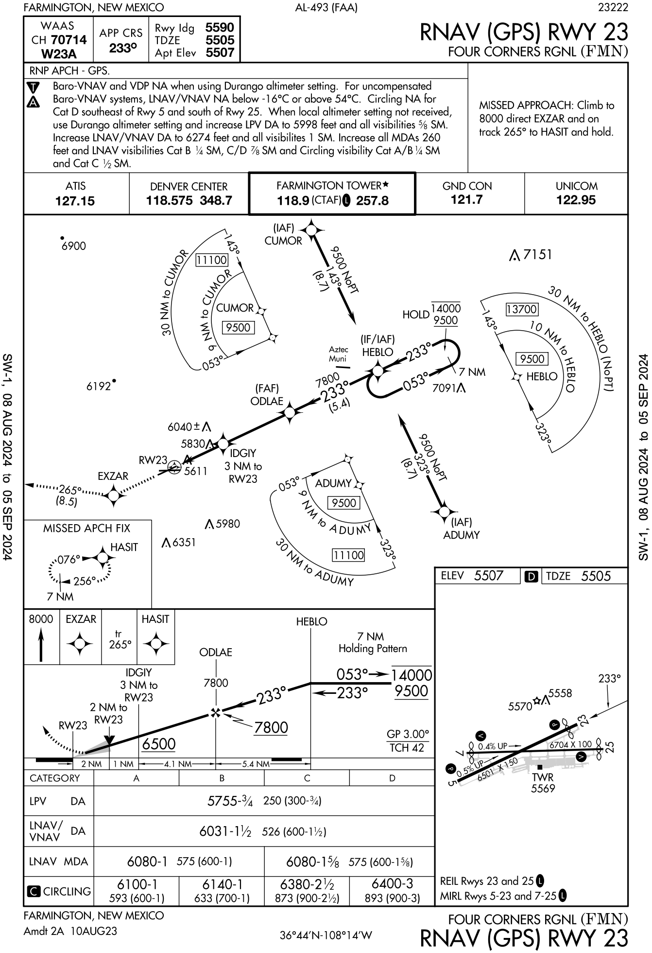
Regarding HILPT, AIM 5-4-9(a)(5) states (emphasis added):
A holding pattern in lieu of procedure turn may be specified for course reversal in some procedures. In such cases, the holding pattern is established over an intermediate fix or a final approach fix. The holding pattern distance or time specified in the profile view must be observed. For a hold-in-lieu-of-PT, the holding pattern direction must be flown as depicted and the specified leg length/timing must not be exceeded.
The intepretation from this seems to be that the initial outbound can not be shortened.
- See
KFBR RNAV (GPS) RWY 22that has a 7 nm HILPT. - In this case, flying outbound for 1 minute before turning to intercept the inbound leg seems to be inconsistent with the guidance in the AIM.
- See
This same guidance appears verbatim in FAA-H-8083-16B Instrument Procedures Handbook on page 4-49.
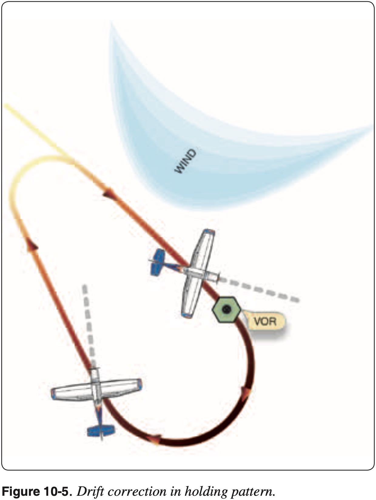
Compensating for Wind
- When flying a holding pattern, the effects of wind need to be compensated for to ensure the hold is flown within the airspace protected for that hold
- In timed holds, both crosswind corrections and timing corrections must be made
- In distance holds, only crosswind corrections need to be made
- The most important thing is to stay within the protected airspace for the hold
TIP
When executing a hold, don't overthink the rules-of-thumb below. Instead, come up with a reasonable adjustment to the outbound and fly it, don't get fixated on perfecting mental math. It's OK to round off a degree of heading or second of time.
Timing corrections
- Adjust outbound to achieve 1 minute inbound legs
- Time the outbound leg when abeam the fix
Abeam the fix is most accurately determined by flag flip
- This is consistent with guidance in AIM 5-3-8(g) and AIM 5-3-8(j)(4)(b):
Outbound leg timing begins over/abeam the fix, whichever occurs later. If the abeam position cannot be determined, start timing when turn to outbound is completed.
If the abeam position cannot be determined, start timing when turn to outbound is completed
- If you fly an initial outbound leg of 1 minute and that gives an inbound leg of 50 seconds, then
- Take this deficit of 10 seconds
- Multiply it by 1.5 and apply it to the next outbound leg
- This would give an outbound leg of 1:15
- If you have a wind vector in the cockpit, fly an extra second outbound per knot of headwind on the outbound leg
- Some rules-of-thumb propose flying an extra half second outbound per knot of headwind on the outbound leg
- No timing corrections are to be made on the initial outbound
- See AIM 5-3-8(j)(4)
- Note: it is better to go out a bit further and give more time on the inbound than cutting the inbound too tight
Crosswind corrections
- To compensate for crosswind, triple the inbound wind correction angle on the outbound leg
- So if heading 10° right of the inbound course is required to stay on course, on the outbound leg use a 30° wind correction to the left
- This rule-of-thumb works well for 1 minute holds, for 4 nm mile holds, doubling the inbound wind correction works better.
- Do not compensate for wind when turning - just fly standard rate turns (15° bank angle)
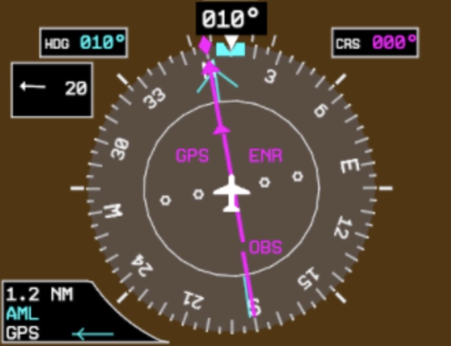
Using Track Diamond
NOTE
In aircraft equipped with track information displayed on the HSI, the application of proper crosswind corrections is made easier.
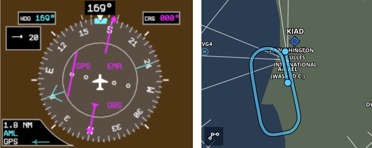
- Consider the following hold: "Hold south of the AML VOR on the 180 radial, left turns"
- This means our inbound
CRSis 360 - There is a 20 knot wind from the East
Note Inbound Crosswind Correction
- To make proper crosswind corrections throughout the hold, first note the required crosswind correction when established inbound
- Once established inbound on a
TRKis 360, andHDGis 010, giving a 10° crosswind correction to the right
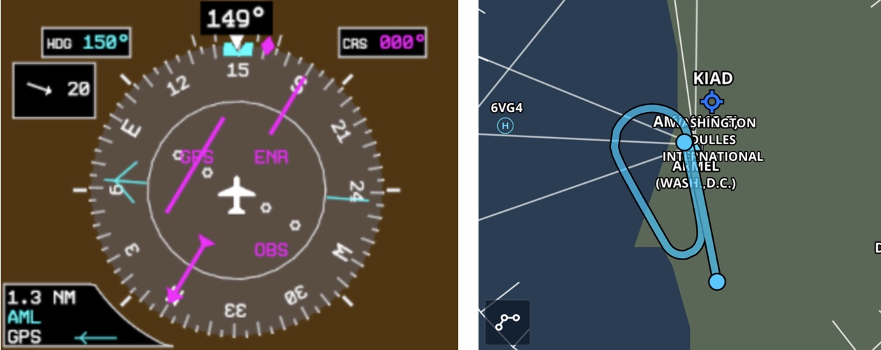
Incorrect Outbound Crosswind Correction
- This shows what the hold would look like if we made the incorrect crosswind corrections on the outbound, using the same crosswind correction as the inbound
Correct Outbound Crosswind Correction
- This shows the correct crosswind corrections on the outbound, multiplying the inbound crosswind correction by 3
- This gives us an outbound heading of 150
Unpublished Holds
- Holds can be published or unpublished
- When the hold is not published an ATC clearance will specify
- Location of the inbound leg relative to the fix (in terms of N, SE, etc.)
- Holding fix
- Radial, course, bearing, airway, or route on which the aircraft is to hold
- Leg length in miles if DME or RNAV is to be used
- Direction of turn, if left turns are to be made
- Time to expect-further-clearance (EFC) and any pertinent additional delay information
- Note how DME holds are defined in the image below
Flying a Hold
Determine Entry, CRS, and TRK
- Determine the hold from the chart or ATC instructions
- Draw the hold on the chart to help with situational awareness and ensure the hold is flown as cleared
- Determine inbound course (
CRS)- This may or may not be the same as the radial that defines the inbound leg
- Determine hold entry
- Determine the initial outbound track (
TRK)- Alternatively heading in aircraft not equipped to provide track information
Prior to Entry
- Prior to entering the hold
- Start slowdown 3 minutes before reaching holding fix
- Remember it's a good idea to ask ATC to slow down as soon as you are expecting to hold
- There are references in AIM 5-3-8 regarding this slowdown 3 minutes prior to the hold in reference to slowing below maximum holding speed.
- For general aviation a better reference is FAA-S-ACS-8C Instrument Rating Airplane Airman Certification Standards that specifies a slowdown 3 minutes prior to reaching the holding fix and states power should be set to conserve fuel.
- Power 2100 RPM
- Use a little left rudder
- 2 slow turns of nose-up trim
- Airspeed should be about 90-95 KIAS
- Start slowdown 3 minutes before reaching holding fix
Initial Outbound
- Crossing the holding fix run T + 5 T's
- Toggle
- Switch to
OBS/SUSPas necessary SUSPprevents the GPS from sequencing- For example, if we are holding in a HILPT and need to remain in the hold instead of sequencing on the the rest of the approach
OBSalso suspends GPS from progressing to next waypoint and allows us to dial in a radial- For example, if we've been given an unpublished hold
- Switch to
- Turn
- Turn to the outbound track (or heading) determined by the entry procedure
- Time
- Start the timer when wings are level
- Twist
- Twist OBS to inbound course
- Twist heading bug to outbound heading
- Throttle
- Set throttle for holding speed
- This should have been done within 3 minutes of holding fix
- Talk
- Talk to ATC as needed or requested
- Toggle
- When the timer reaches 1 minute or whatever the length or duration outbound of the hold is supposed to be then run the 5 T's again
- Turn
- Inbound
- Time
- Reset the timer
- Twist
- Twist heading bug to inbound heading
- Throttle
- Verify throttle setting
- Talk
- Talk to ATC as needed or requested
- Turn
- Established inbound run the 5 T's again
- Turn
- Heading as needed to maintain inbound course
- Time
- When getting established back inbound start the timer at the first of
- Wings level
- Course centered
- When getting established back inbound start the timer at the first of
- Twist
- Heading bug to inbound heading
- Throttle
- Verify throttle setting
- Talk
- Talk to ATC as needed or requested
- Turn
- Crossing the fix run the 5 T's again
- Turn
- To outbound heading
- Time
- Note time of inbound leg
- Reset timer
- Twist
- Heading bug to outbound heading
- We should know what the outbound heading is based on wind correction on our inbound leg
- Throttle
- Verify throttle setting
- Talk
- Talk to ATC as needed or requested
- Turn
- When completing the turn and heading outbound
- Time the outbound leg when abeam the fix
- Abeam the fix is most accurately determined by flag flip
- If the abeam position cannot be determined, start timing when turn to outbound is completed
- AIM 5-3-8(g)
- Repeat this process for each turn in the hold
- Exiting the hold and returning to cruise
- Full power
- A little right rudder
- 2 turns of nose-down trim
- At 100 KIAS power to 2400 RPM
- Trim as required
Review of Timing
- When initially crossing the fix and turning outbound
- Start the timer when wings are level
- This buys a bit of extra time on the outbound leg
- When getting established back inbound
- Start the timer at the first of
- Wings level
- Course centered
- Start the timer at the first of
- When completing the turn and heading outbound
- Time the outbound leg when abeam the fix
- Abeam the fix is most accurately determined by flag flip
- If the abeam position cannot be determined, start timing when turn to outbound is completed as indicated by wings level
- AIM 5-3-8(g)
- See the example below
Holding Speed Limits
- There are limits on the maximum holding airspeed that must be complied with
- See table below
Operational Notes
- When holding at a VOR, for example, use pink needles (GPS) instead of green needles
- Recall 60:1 rule - 60 nm from VOR each degree is 1 nm
- Also recall cone of confusion
- Use the MFD to your advantage to see how the aircraft is tracking relative to what you want
- Additional notes
- When substituting GPS for DME distance, slant-range distance is usually negligible
- Know how your aircrafts RNAV/FMS will provide guidance / exectute the hold, as different systems may behave differently, and in some cases can cause a hold to extend outside the protected area
- For example, distance specified in terms of inbound leg rather than outbound
References
- FAA-H-8083-15B Instrument Flying Handbook
- Chapter 10: IFR Flight
- Page 10-10: Holding Procedures
- Chapter 10: IFR Flight
- PilotsCafe Holding Procedures 101
Arrival and Approach Procedures
Arrival Procedures
- Arrival procedures transition the instrument pilot from the en route structure to a fix in the terminal area from which an instrument approach can be conducted
- FAA-H-8083-15B Instrument Flying Handbook
- Chapter 10: IFR Flight
- Page 10-9: Standard Terminal Arrival Routes (STARs)
- Chapter 10: IFR Flight
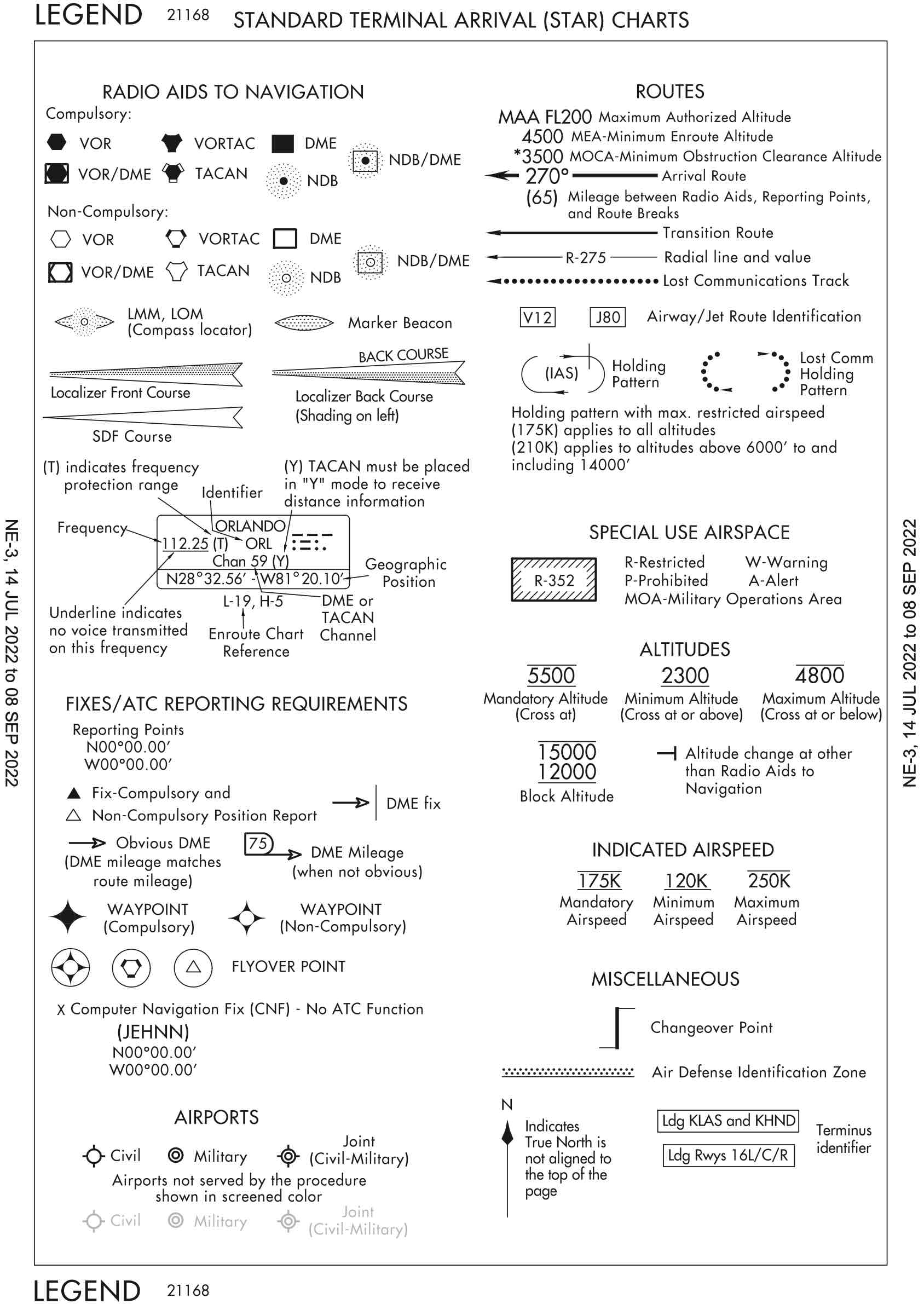
Standard Terminal Arrival (STAR)
- "Fly" vs. "Descend via" the arrival
- FAA Climb Via/Descend Via Speed Clearances Frequently Asked Questions
- Descend via
- Comply with the lateral path of the STAR
- Comply with all published speed restrictions
- Comply with all published altitude restrictions
- "Descend via" means we can descend to the lowest altitude restriction on the STAR
- So if a given waypoint has, for example, a restriction to cross at or above 10,000', then that is the lowest we can descend until cleared lower
- Can only descend lower with clearance to do so, or if cleared for an approach
- Being told to expect a particular runway or approach is not sufficient to descend lower
- Similar rules apply for "Climb Via" with respect to a SID
Terminal Arrival Areas (TAA)
- AIM 5-4-5(d)
- The TAA provides a transition from the en route structure to the terminal environment with little required pilot/air traffic control interface for aircraft equipped with Area Navigation (RNAV) systems.
- Basic RNAV approach procedure underlying TAA is the "T" structure
- 30 nm radius around each of the IAFs
- An aircraft inside a TAA is established on a published segment of an approach
- Obey minimum altitudes when in the TAA and cleared for the approach
- TAAs provide a structure to help understand how the approach will commence, including which IAF it will start from, whether the hold-in-lieu of procedure turn is needed, and what altitude to fly, but this should all be depicted anyhow via e.g. NoPT, and controller communication as to which fix the pilot is cleared to and at what altitude. If in doubt, confirm with ATC.
- BruceAir: Terminal Arrival Areas (TAA)
Instrument Approach Procedures
Approaches Overview
Instrument Approach Procedure
A series of predetermined maneuvers for the orderly transfer of an aircraft operating under instrument flight rules from the beginning of the initial approach to a landing, or to a point from which a landing may be made visually.
- There are three main types of instrument approach procedures (IAP)
- Non-Precision Approach (NPA)
- No vertical guidance
- Examples: VOR, TACAN, LNAV, NDB, LOC, and ASR
- Precision Approach (PA)
- Has vertical guidance meeting ICAO standards
- Examples: PAR, ILS, and GLS
- Approach with Vertical Guidance (APV)
- Provides course and glidepath deviation information but not to ICAO standards (Annex 10)
- Examples: Baro-VNAV, LDA with glidepath, LNAV/VNAV and LPV
- Non-Precision Approach (NPA)
- Additionally there are
- Circling Approaches
- Visual Approach
- Is not an instrument approach procedure (IAP)
- Contact Approach
- Similar to a visual approach, but with lower visibility minimums
- Approaches that do not have straight-in landing minimums are identified by the type of approach followed by a letter.
- Find Standard Instrument Approach Procedure Charts in the Digital Terminal Procedures Publication
- Updated every 28 days
- Approach Gate
- The approach gate is an imaginary point used within ATC as a basis for vectoring aircraft to the final approach course.
- The gate is established along the final approach course one mile from the FAF on the side away from the airport and is no closer than 5 NM from the landing threshold.
Aircraft Approach Categories
- Approach categories are defined in 14 CFR §97.3 Symbols and terms used in procedures
- Aircraft approach category means a grouping of aircraft based on a reference landing speed (
), if specified, or if is not specified, 1.3 at the maximum certified landing weight. - Approach categories define the minima used for a given approach
- Aircraft category also impacts circling radius
- See the following category limits noting that the airspeeds depicted are indicated airspeeds (IAS):
- Category A: Speed less than 91 knots.
- Category B: Speed 91 knots or more but less than 121 knots.
- Category C: Speed 121 knots or more but less than 141 knots.
- Category D: Speed 141 knots or more but less than 166 knots.
- Category E: Speed 166 knots or more.
- An airplane is certified in only one approach category, and although a faster approach may require higher category minimums to be used, an airplane cannot be flown to the minimums of a slower approach category.
- Cessna 172 is Category A
Altitudes
- Minimum Descent Altitude (MDA)
- The lowest altitude, expressed in feet MSL, to which descent is authorized on final approach or during circle-to-land maneuvering in execution of a standard instrument approach procedure (SIAP) where no electronic glideslope is provided.
- Decision Altitude (DA)
- Specified altitude in the precision approach at which the decision to continue or execute the missed approach must be initiated if the required visual reference to continue the approach has not been established.
- Decision Height (DH)
- With respect to the operation of aircraft, means the height at which a decision must be made during an ILS, MLS, or PAR IAP to either continue the approach or to execute a missed approach.
- Minimum Safe Altitude (MSA)
- Provided on approach charts for emergency use
- Provide 1,000' of obstacle clearance
Chart Overview
TIP
Know how to read an instrument approach chart, review charts before flight, and make sure to have the charts during flight.
- Components of approach chart
- Margins
- Briefing strip and procedure notes
- Plan view
- Profile view
- Minimums
- Airport diagram
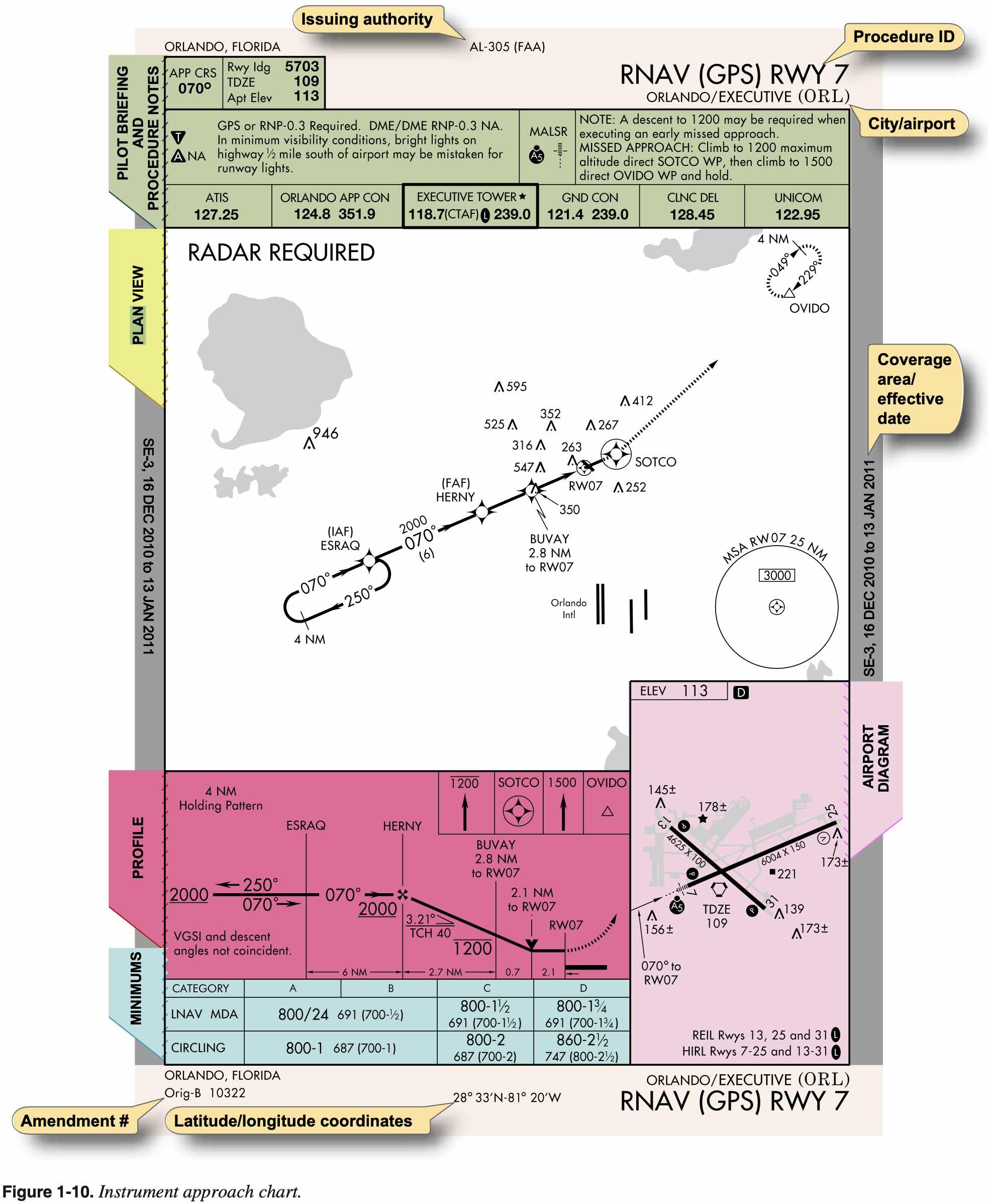
- The Digital Terminal Procedures Publication (d-TPP)/Airport Diagrams has the legend for instrument approach procedures.
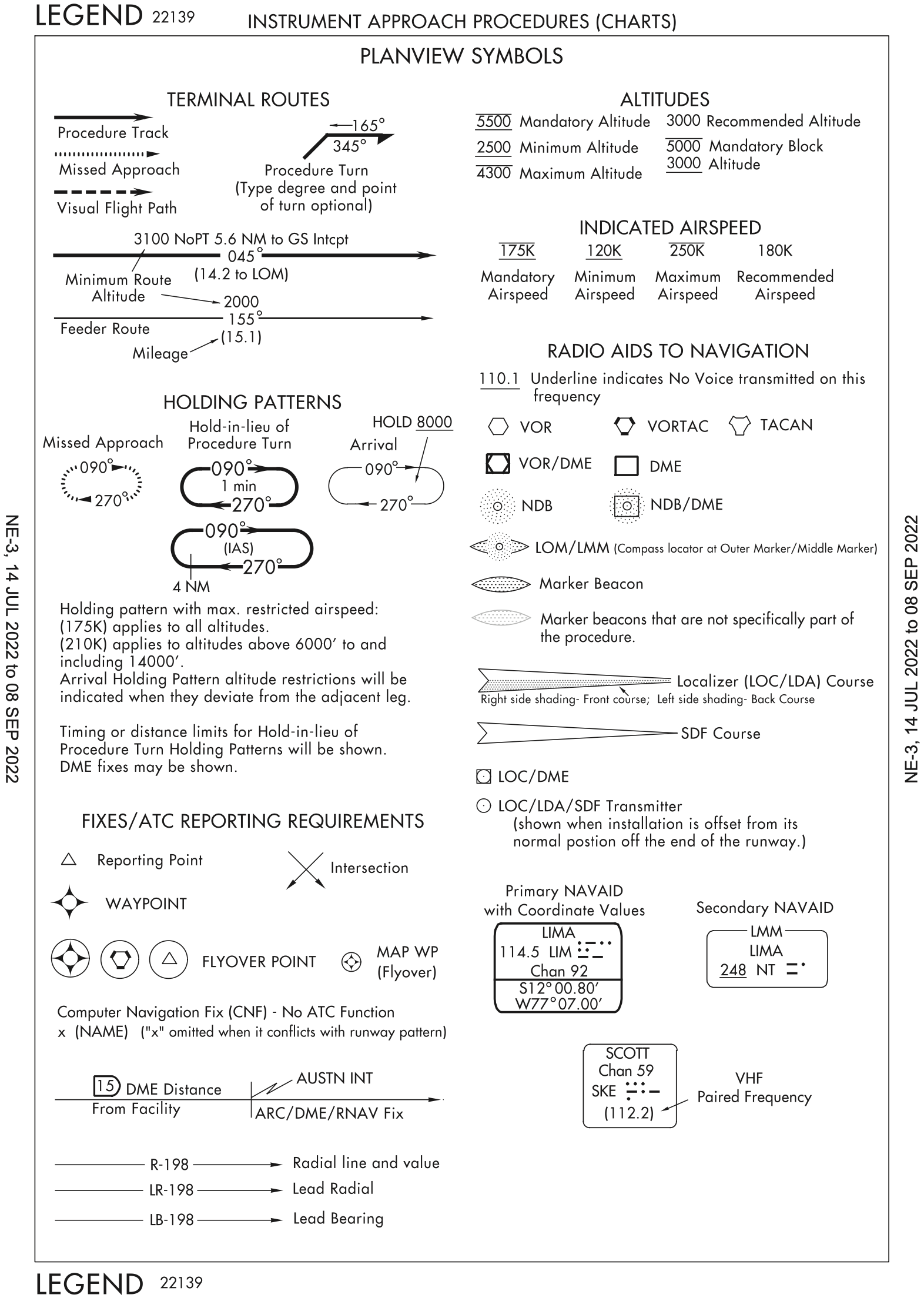
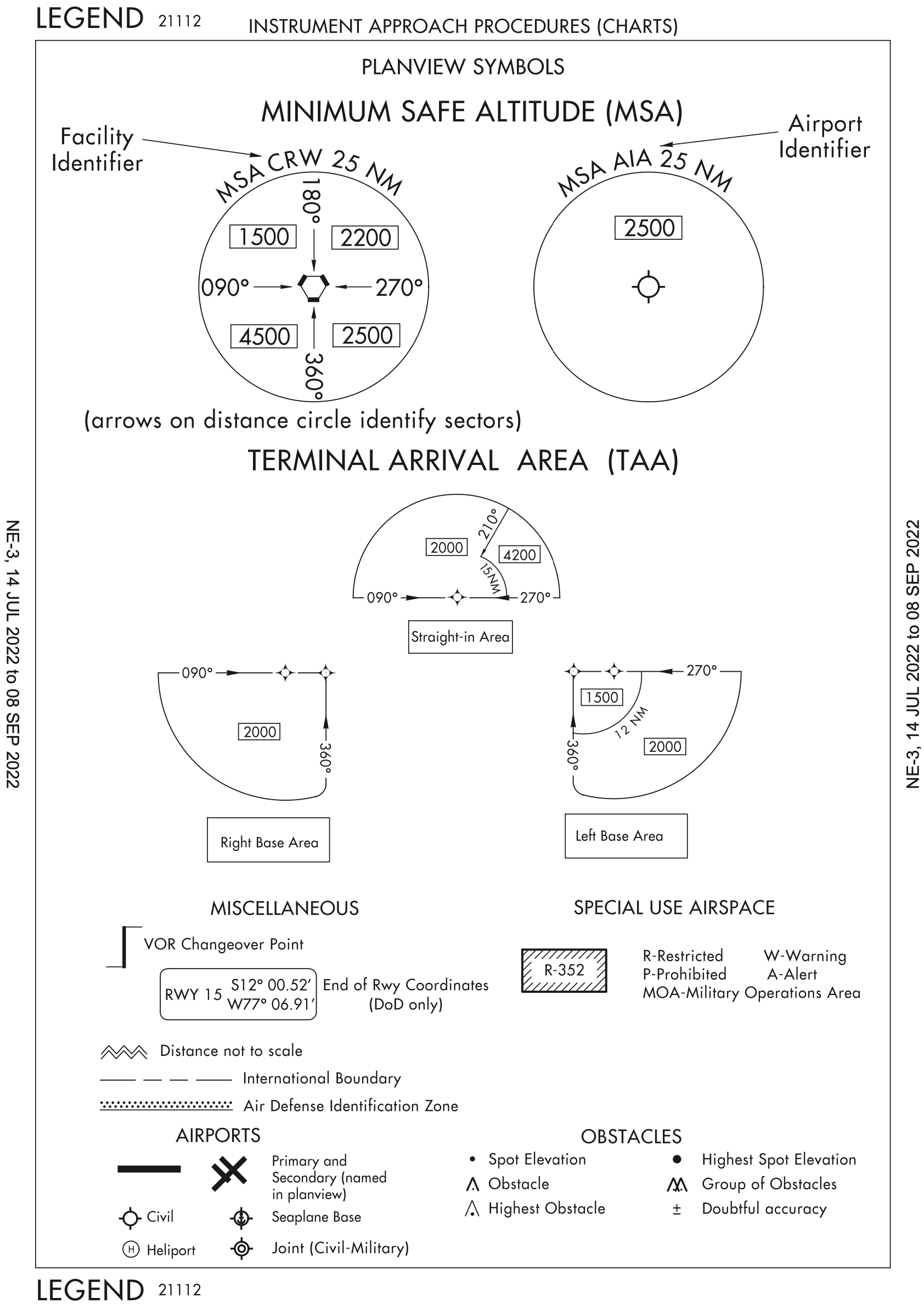
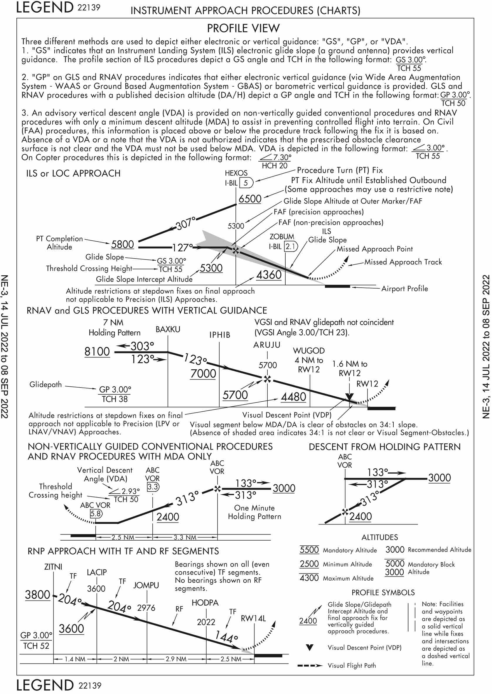
MSA and TAA
The Minimum Safe Altitudes (MSA) is published for emergency use on IAP or departure procedure (DP) graphic charts. MSAs provide 1,000 feet of clearance over all obstacles, but do not necessarily assure acceptable navigation signal coverage.
Altitudes published within the TAA replace the MSA altitude. However, unlike MSA altitudes the TAA altitudes are operationally usable altitudes. These altitudes provide at least 1,000 feet of obstacle clearance, more in mountainous areas.
Equipment Requirements
When radar or other equipment is required for procedure entry from the en route environment, a note will be charted in the planview of the approach procedure chart (e.g., RADAR REQUIRED or ADF REQUIRED). When radar or other equipment is required on portions of the procedure outside the final approach segment, including the missed approach, a note will be charted in the notes box of the pilot briefing portion of the approach chart (e.g., RADAR REQUIRED or DME REQUIRED).
Briefing the Approach
- There is no standard way to do an approach briefing
- Learn how to do a complete brief
- Depending on how low on the approach we are expecting to break out and go visual will dictate the level of depth of the approach brief
- How the Missed Approach Point (MAP) is determined must be part of briefing
- Precision: DA (Note: DA is the prefered term versus DH)
- If when shooting the approach we only see the approach lights, we can continue to descend to 100 feet above the TDZE
- That is why this is important to brief
- Tthe "identification" of some fixes on NPA which allows further stepdown
- Optional fixes - allow lower minima for aircraft that can identify them
- The WIRE checklist can be used to setup for an instrument approach
- W - Weather
- I - Instruments
- R - Radios
- E - Enroute briefing
- The ABC checklist is an alternative to the WIRE checklist for the same purpose
- A - ATIS
- B - Build + Brief
- C - Checklist
- Or alternatively:
- Listen
- Load
- Brief
- The enroute briefing is something like what's in How do you Brief an Approach Using FAA/NACO Charts although I have modified it slightly.
- Type of Approach & Location.
- Check the Date
- Navigation
- Final approach course.
- TDZE
- If you have the approach lights system at DA/MDA, you can continue to 100' above TDZE. 91.175(c)
- Type of Lighting System
- Minimum Safe Altitudes (MSA) and terrain
- Glide slope crossing altitude (precision), or final approach fix location and altitude (non-Precision).
- Glide slope intercept altitudes
- Other frequencies required for the approach. Example, DME or VOR cross radials if GPS is not available.
- DA or MDA, and visibility requirements and current visibility
- Taxi plan after you land.
- Missed approach point, and the initial portions of the missed approach procedure (heading & altitude).
- Missed approach frequencies.
- "Any questions?" if flying with another pilot
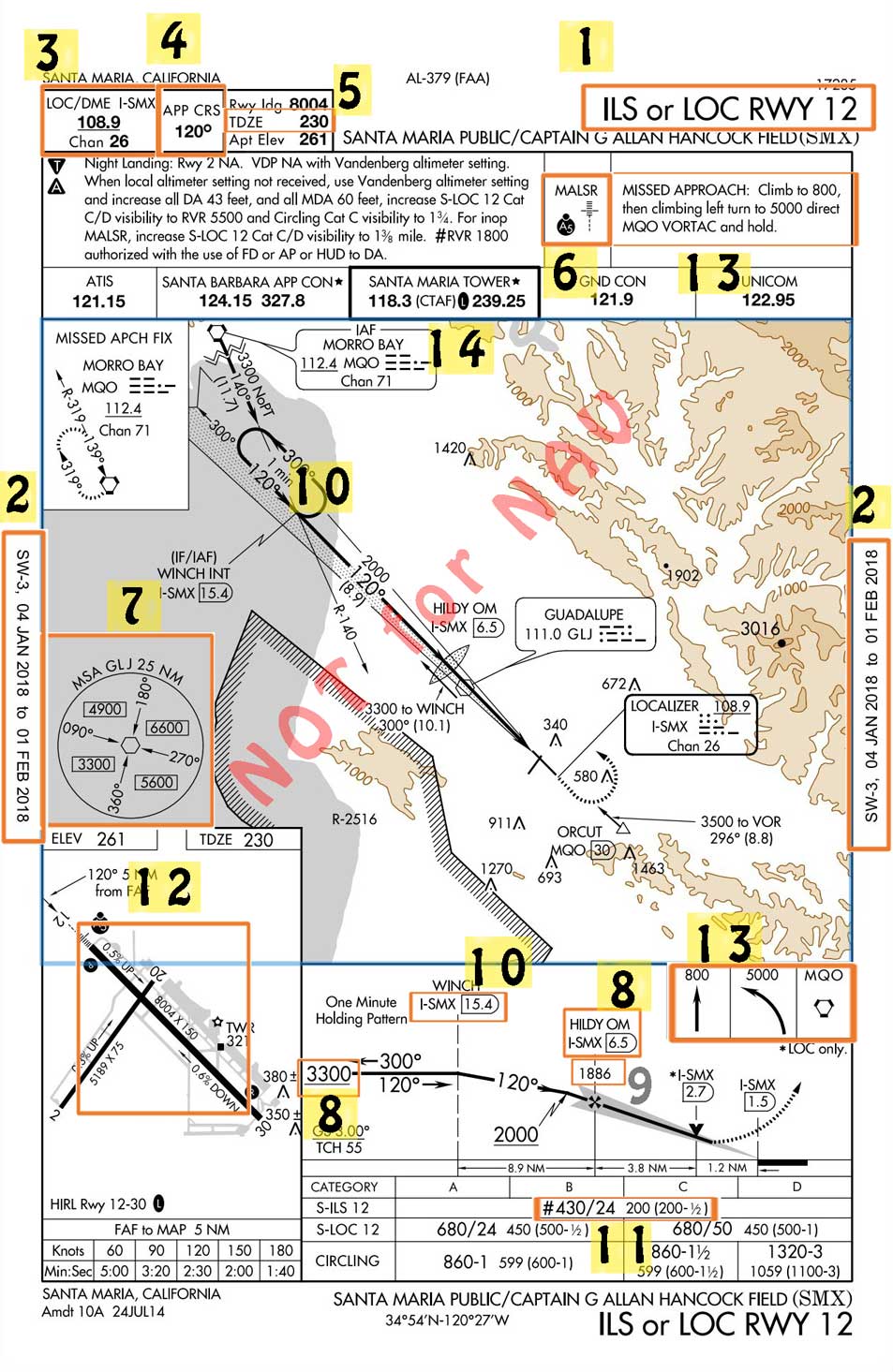
Example Approach Briefing
- Run WIRE checklist
- Weather - get the ATIS
- Instruments
- Altimeter
- Localizer frequency, course
- Missed approach in standby
- Radios
- Set up comm 1/2 active/standby preparing for missed
- Comm 1 active: approach
- Comm 1 standby: tower
- Comm 2 active: ATIS
- Comm 2 standby: doesn't matter
- Set up comm 1/2 active/standby preparing for missed
- Enroute briefing
- Before enroute briefing
- Verify correct chart for given approach
- Verify chart expiration date
- Brief
- We are doing the ILS 12 in Santa Maria.
- The chart dates are valid.
- We are currently (location relative to airport) at (altitude)
- Localizer frequency 108.9 set in nav 1 and 2 active AND identified
- Heading bug set to final approach course 120
- Touch down zone elevation TDZE is 230 feet with 8004 ft runway
- Approach light system is a MALSR, with PAPI on the right.
- Minimum Safe Altitude (MSA), 3300' from the quadrant we are approaching.
- WINCH at or above 3300' and Final Approach-HILDY 1886'.
- DME source is from the localizer frequency. We need MQO (No GPS) to identify WINCH on R-140 from MQO.
- Decision Altitude, 430'.
- If we have the approach lighting system in sight, we can descend to 330' (100' above TDZE).
- We need 1/2 sm, we have 1sm visibility.
- When we land, we can plan for a left turn on A5, right on A, and left at the FBO (look at the airport diagram).
- If we have to go missed approach, climb runway heading to 800'. Then a climbing left turn, direct Morro Bay, and hold. We are going to be doing a parallel entry.
Procedure Turns
- See FAA-H-8083-15B Instrument Flying Handbook
- Page 1-20
- Page7-30
- Common on VOR approaches
- 200 KIAS speed limit
- Remain within 10 nm
- Turn in the direction of the barb
- Give yourself enough room to descend
- Not authorized if
NoPTon approach plate - The absence of the procedure turn barbed arrow in the plan view indicates that a procedure turn is not authorized for that procedure
- From before the days of GPS and DME where often VOR were the IAF, and pilots flying for long distances between VORs arriving at the IAF could do the procedure turn to buy a bit of time
- With GPS we have distance so no need for procedure turns
- Controllers prefer to give vectors to make things faster
- If we want the procedure turn need to ask ATC for it
- When must a procedure turn be flown
- Always except
- When it says
NoPT - If you are getting vectors to the final approach course
- If it is a timed approach from a holding fix
- By pilot or controller agreement
- If ATC says, for example, cleared for the straight-in ILS 32 at KOKV
- When it says
- "Straight-in" has two meanings
- One is the alignment of final approach course with runway
- The other, in context of procedure turns, is where a procedure turn is not used
- 14 CFR §91.175(j)
- AIM 5-4-9 Procedure Turn and Hold-in-lieu of Procedure Turn
- The same is true for a hold-in-lieu of procedure turn
- If charted it must be flown, unless one of the above exceptions is met
- Always except
- Procedure turn usually needs to be completed within 10 nm
- In Cessna, go out about 8 miles and then turn out for 1 minute
- When getting vectored should be at least 2 nm or more from FAF
- This is from ATC handbook
- In 172 we teach to fly the approach at 80 knots (so Cat A)
- One good reason for this is it keeps us 5 knots below our flap speed
- Do not fly a procedure turn when SHARP TT
- S - Straight-in approach clearance
- H - Holding in lieu of a procedure turn
- A - DME Arc
- R - Radar vectors to final
- P - No PT depicted on chart
- T - Timed approach from a hold fix
- T - Teardrop course reversal
- Airliner approaches are 120 - 130 knots
- Smaller jets approach at 110 - 120 knots
- So in a 172 we can fly the approach at 120 knots and we'll fit in with most other traffic
Initiating an Approach
Minimums do not preclude flights under Part 91 from initiating an approach
- You can "take a look"
- 121 and 135 operators must have weather at or above minimums as reported on ATIS/AWOS in order to even begin the approach
Standard instrument approach procedures (SIAP) must begin at an initial approach fix (IAF) or an intermediate fix (IF) if there is not an IAF.
Continuing the Approach / Descending Below MDA or DA
- See 14 CFR §91.175(c) Operation below DA/DH or MDA
- DA, as name implies, is altitude at which a decision must be made
- Descent below DA is allowed when going missed due to downward momentum
- Up to about 40 feet below DA is acceptable
- Three requirements to descend below DA or MDA
- Flight visibility
- Flight visibility must be observed to be above minimums
- This is the visibility on the approach plate, and we as the pilots determine if that is met
- Different from reported visibility
- Note approach lights, runway markings, runway length as a gauge for flight visibility
- Approach light systems are usually 2,400 - 3,000 ft.
- TDZ markings are 500 ft. apart for a total of 3,000 ft.
- Runway lights are 200 ft. apart
- Amber lights indicate 2,000 ft. or 1/2 runway remaining
- Runway environment in sight
- Be able to distinctly identify one of the following visual references (ATRVTR)
- A - Approach lights
- Approach lights alone only allow descent to 100 ft. above TDZE
- From that point must be able to see any other parts of the runway environment to continue to descend and land
- T - Threshold
- Markings
- Lights
- R - REILS
- V - VASI (or PAPI)
- T - Touchdown
- Lights
- Zone
- Markings
- R - Runway
- Lights
- Markings
- Normal maneuvers (stabilized approach)
- No official definition
- For us, no more than a forward slip
- Want to get the airplane on the ground in first 1/3 of runway
- Flight visibility
- Learn length of MALSR/ALS etc.
- Know types of lighting or where to find them
- If we don't have the flight visibility required by the approach, are not supposed to land
- This can be because of low-lying radiation fog, for example
- So if you arrive at MAP and can see any of the above, can descend and land
- When briefing the approach, note the type of approach lights, location of VASI/PAPI, and build in your mind a picture of what you need to see in order to have the required flight visibility
- In crewed operation (with pilot flying and pilot monitoring)
- "lights" - called out by PM to indicate lights are in sight
- "continuing" - called out by PF to indicate they will descend to 100 feet above TDZE
- "runway" - called out by PM to indicate runway is in sight
- "landing" - called out by PF to indicate they will land
- Pre-make decisions
- Plan of action
- Ask ATC where people are going and getting in successfully
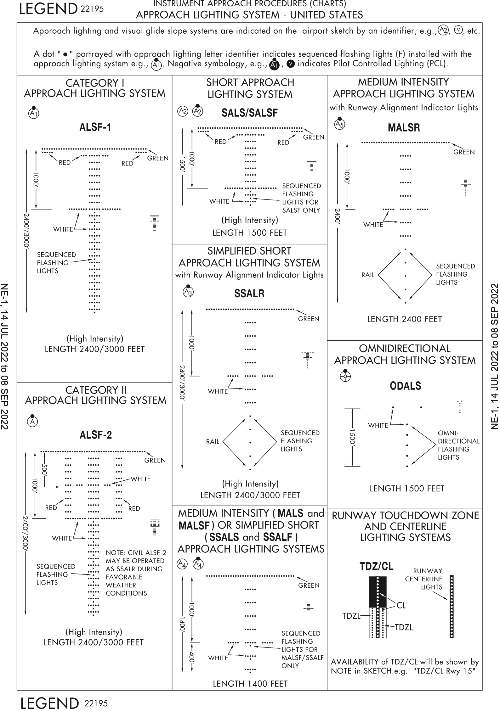
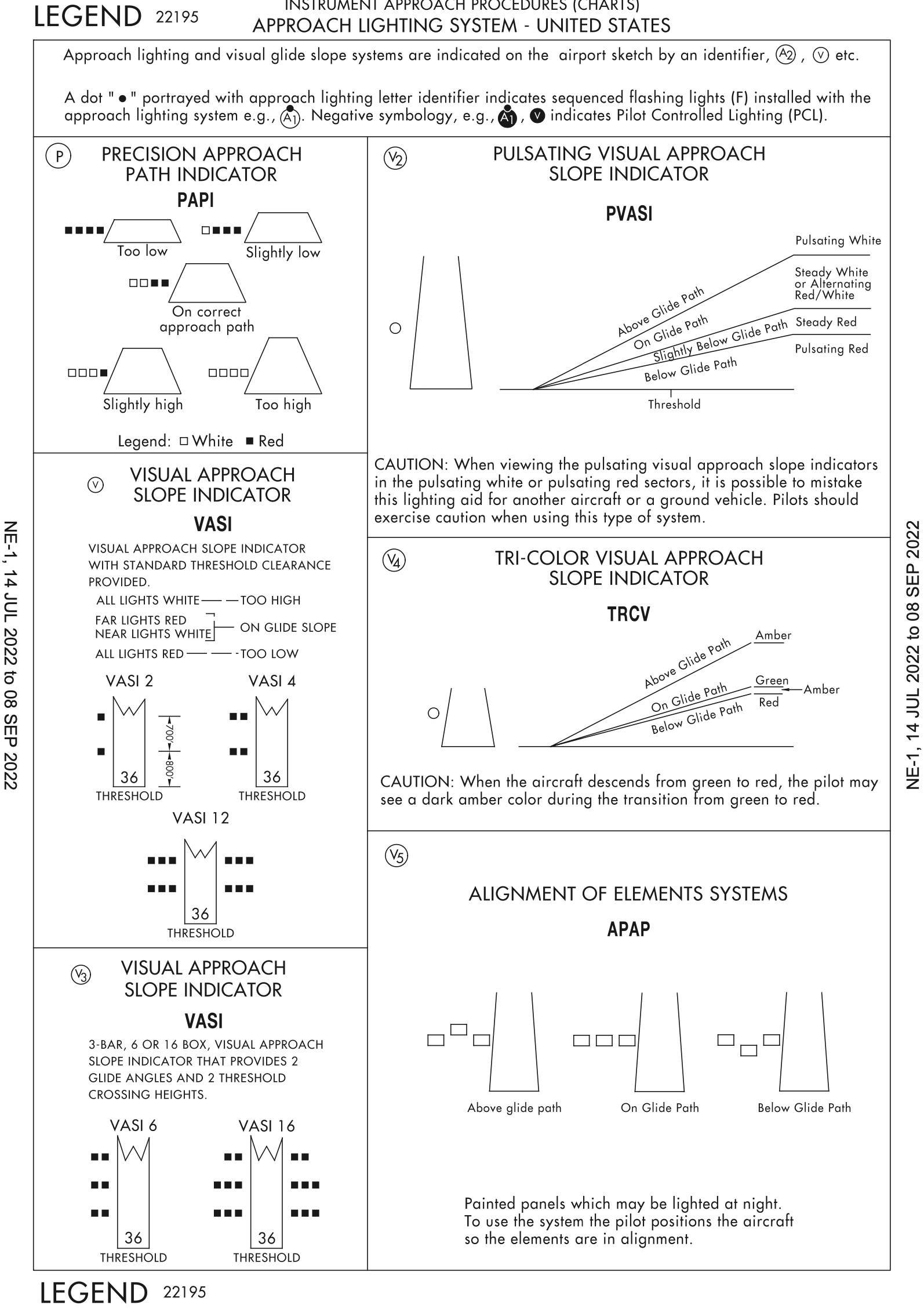
Canceling IFR
- Good idea to do as soon as you can safely make it to airport under VMC
- This frees up the runway for use by other traffic more quickly
- Locks up runway for 30 minutes or until they locate you
Precision Approach
This page covers Task B. Precision Instrument Approach (PA) from the FAA-S-8081-9E Flight Instructor Instrument Practical Test Standards.
Precision Approach Definition
Precision Instrument Approach
Uses a navigation system that provides lateral and vertical course guidance.
Types of Precision Approaches (PA)
- Instrument Landing System (ILS)
- The "standard" precision approach
- Has localizer for lateral guidance and glideslope for vertical guidance
- Requires equipment installed at the airport
- Localizer Performance with Vertical guidance (LPV)
- Is technically not a precision approach but rather an approach with vertical guidance (APV)
- For our purposes these are flown just like precision approaches, but just have a different name
- Are not precision approaches because they don't meet ICAO standards (Annex 10)
- GPS equivalent of ILS
- Same accuracy (width) as a localizer
- Requires WAAS-GPS
LPVon GPS display- See overview section on GPS Approaches
- Precision Approach Radar (PAR)
- Dedicated radar site with two dishes, one horizontal and one vertical
Chart Review
- Review
KHEF ILS RWY 16Lapproach chart - A few notes
- Triangle
AandT- Nonstandard alternate and takeoff minimums
- Alternate minimums see Digital Terminal Procedures Publication (d-TPP)/Airport Diagrams
- ForeFlight
Procedure>Arrival>ALTERNATE MINIMUMS
- ForeFlight
- Takeoff minimums see Digital Terminal Procedures Publication (d-TPP)/Airport Diagrams
- ForeFlight
Procedure>Departure>TAKEOFF MINIMUMS
- ForeFlight
- Note lighting and that is pilot controlled
- See legend below
- More on why this is important below
- Note dark
Cfor expanded circling radius- See legend in the Terminal Procedures Publication
- Final approach fix for a precision is glideslope intercept given by lightning bolt symbol
- Below profile view in the minimums strip
- Altitudes MSL, visibility, then AGL
- In parentheses for military
- Note different approach categories
- Note 3° glideslope and Threshold Crossing Height (TCH) of 58'
- For us we are flying down to Decision Altitude (DA)
- TDZE is defined as the highest elevation in the first 3,000 feet of the landing surface
- Airport elevation is defined as the highest point of an airport's usable runways measured in feet from mean sea level.
- Triangle
Beginning a Precision Approach
- Load the approach
- Load the full approach and then if getting vectored press "activate vectors to final"
- That way if ATC changes their mind about vectoring us and wants to send us to a point on the approach, it's already there and ready to go
- Load the approach on the ground with the flight plan when able
- Dial the localizer frequency into NAV radio
- This should happen automatically when the approach is loaded
- Recommend putting the ILS frequency into both NAV radios in case one fails
- Glideslope comes with "for free"
- Identify the localizer frequency
- See morse code in plan view of approach chart
- The G-1000 can identify it for us - see code next to NAV frequency
Flying an ILS
- The Course Deviation Indicator (CDI) needle indicates where the course is relative to us
- For example, if the course needle is to the right, the course is to our right
- The glideslope diamond shows the location of the glideslope relative to us
- For example, if the diamond is above center, the glideslope is above us
- Localizer and glideslope signals get more sensitive the closer we get
- Usually given a heading and told to intercept the localizer
- Plan accordingly depending on heading given and winds
- Intercept glideslope from below to avoid false glideslope
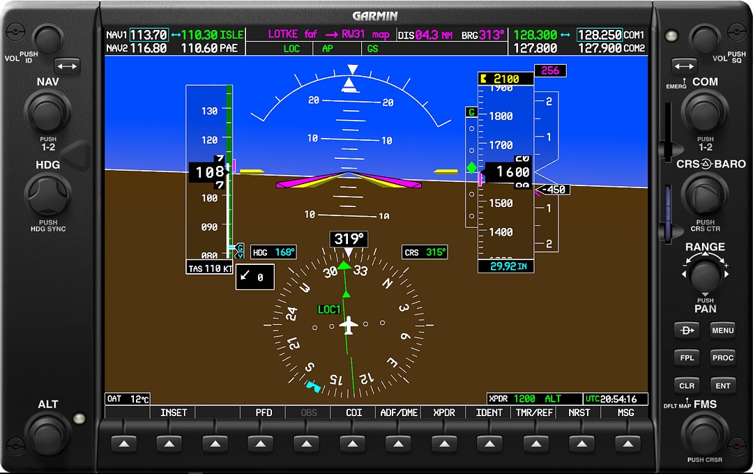

Precision Approach Procedures (Cessna 172S)
- When cleared for approach
- Taxi light on
- If non-towered field, landing light on also
- When established inbound
- Mixture rich, timer zeroed
- Half dot above GS/GP intercept
- 1800 RPM, hold altitude
- At flap speed
- 10° of flaps
- At GS/GP intercept
- Adjust pitch to glideslope/glidepath, power to 80 KIAS
- At FAF
- Start timer, cross check altitude: "GS (or GP) verified"
- Always start timer at FAF because a plane could enter the ILS critical area on ground and block glideslope, then you can keep flying as localizer approach
- Also keeps you in habit so you never forget to start the timer when you do need to
- When cleared to land
- Landing light on
- If criteria not met at Decision Altitude (DA)
- Execute missed approach
Precision Approach Radar
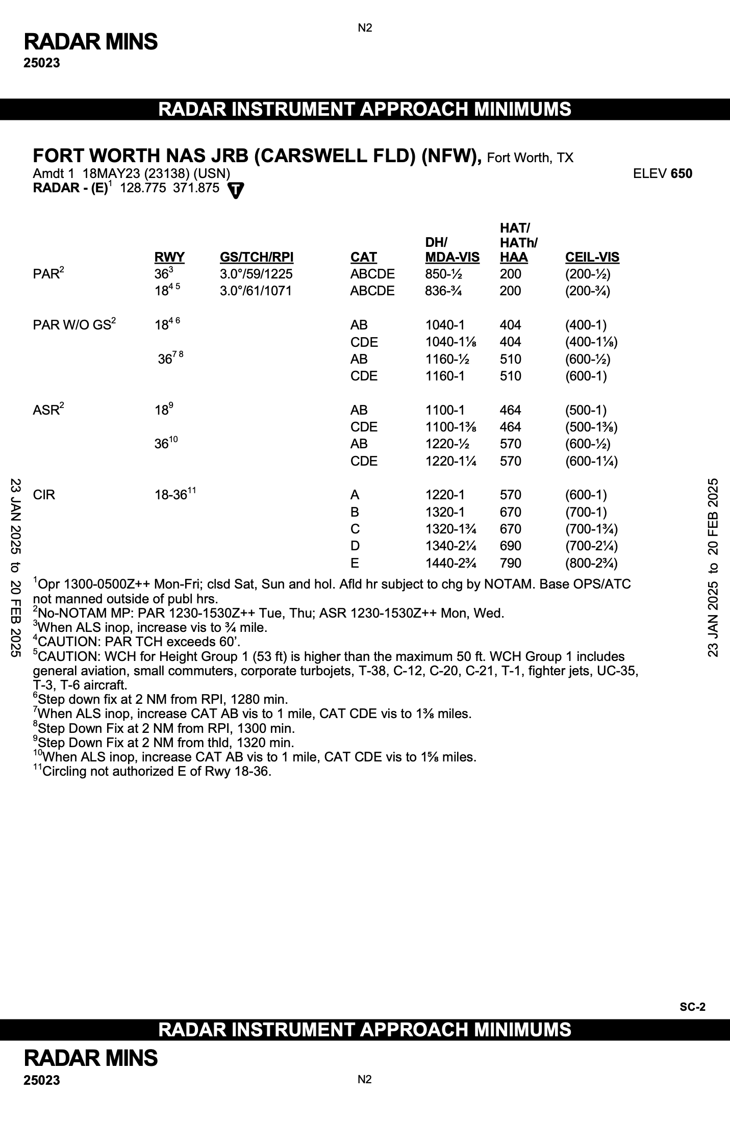

Common Errors
- Failure to have essential knowledge of the information on the instrument approach procedure chart
- Incorrect communications procedures or noncompliance with ATC clearances
- Failure to accomplish checklist items
- Faulty basic instrument flying technique
- Inappropriate application of DH/DA
Operational Errors
- Failure to understand the fundamentals of ILS ground equipment, particularly the differences in course dimensions.
- Since the VOR receiver is used on the localizer course, the assumption is sometimes made that interception and tracking techniques are identical when tracking localizer courses and VOR radials.
- Remember that the CDI sensing is sharper and faster on the localizer course.
- Disorientation during transition to the ILS due to poor planning and reliance on one receiver instead of on all available airborne equipment.
- Use all the assistance available; a single receiver may fail.
- Disorientation on the localizer course, due to the first error noted above.
- Incorrect localizer interception angles.
- A large interception angle usually results in overshooting and possible disorientation.
- When intercepting, if possible, turn to the localizer course heading immediately upon the first indication of needle movement.
- An ADF receiver is an excellent aid to orient you during an ILS approach if there is a locator or NDB on the inbound course.
- Chasing the CDI and glidepath needles, especially when you have not sufficiently studied the approach before the flight.
Adherance to Stepdowns Prior to FAF
- If the glideslope is flown prior to the final approach fix, the pilot is still required to adhere to altitude restrictions imposed by the stepdowns
- See InFO 11009
Completion Standards
Note from (the older) FAA-S-ACS-8B regarding the use of LPV approaches in lieu of an ILS:
Localizer performance with vertical guidance (LPV) minimums with a decision altitude (DA) greater than 300 feet height above touchdown (HAT) may be used as a nonprecision approach; however, due to the precision of its glidepath and localizer-like lateral navigation characteristics, an LPV minimums approach can be used to demonstrate precision approach proficiency if the DA is equal to or less than 300 feet HAT.
The language changed in the more recent FAA-S-ACS-8C:
The applicant must accomplish a precision approach to the decision altitude (DA) using aircraft navigational equipment for centerline and vertical guidance in simulated or actual instrument meteorological conditions. A precision approach is a standard instrument approach procedure to a published decision altitude using provided approved vertical guidance.
References
Nonprecision Approach
This page covers Task A. Nonprecision Instrument Approach (NPA) from the FAA-S-8081-9E Flight Instructor Instrument Practical Test Standards.
Nonprecision Instrument Approach Types
- LNAV
- See overview section on GPS Approaches
- LNAV(+V)
- LP
- LOC
- 3-6° beam width
- 4 times as sensitive as VOR
- LOC-A, for example (with letter) if approach to runway is too steep (more than 3°)
- See
CBE LOC-A
- See
- VOR
- NDB
- Need to have working ADF onboard unless the approach has a GPS overlay
NDB OR GPS
- Need to have working ADF onboard unless the approach has a GPS overlay
- LDA
- Like a localizer, but there is more than a 3° deviation in its alignment with runway heading
- FAA Order 8260.3G 8-1-2(b)
- This offset is noted on the approach chart either in the localizer box, or near it as a note
- May or may not have a glide slope
- When it has a glideslope it is an APV procedure
- Like a localizer, but there is more than a 3° deviation in its alignment with runway heading
- SDF
- Basically extinct
- Poor man's localizer
- 6-12° beam width
- GPS
- Usually the MAP is a flyover waypoint (4-pointed star with circle around it)
- Think circle or "O" around the star for "over"
- Usually the MAP is a flyover waypoint (4-pointed star with circle around it)
- ASR
- This is TRACON approach controller
- Non-precision version of PAR
Other Approach Types
- Visual approach
- requires 3 sm visibility and 1000' ceilings
- May be requested by pilot
- May be assigned by ATC
- Contact approach
- Requires 1 sm visibility and clear of clouds
- May only be requested by pilot
- Visual contact with ground or preceding aircraft
- No assurance of obstacle clearance
Other Non-precision Approach Concepts
- Visual descent points (VDP)
- Point at which a descent from MDA to runway is made with a 3° angle
- Published on some non-precision approaches with bold "V" near runway
- 3° is about 300'/nm descent so that can be used to calculate VDP if it is not on approach plate
- Should always predetermine a VDP if not published
- GPS can be used instead of the VOR receiver for a VOR approach if the underlying NAVAID is monitored for course guidance
LDA Approach Plate Examples
- May or may not have a glideslope
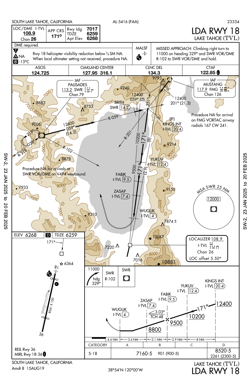
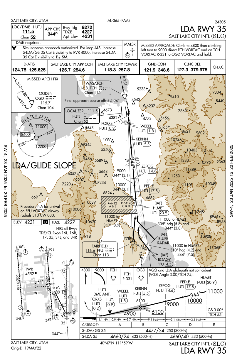
Completion Standards
References
Flight Activities
- Holds
- Unusual attitude
- Intercepting and tracking courses using electronic navigation systems
- Approaches
- Precision
- Non-precision
- Circling
- Missed
- Landing from an approach
- Partial panel approach
References
- 14 CFR §61.57(d) - Instrument proficiency check
- FAA-S-ACS-8C Instrument Rating Airplane Airman Certification Standards
- Instrument Proficiency Check (IPC) Guidance
- FAA-AC-61-98D - Currency Requirements and Guidance for the Flight Review and Instrument Proficiency Check
- FAA-H-8083-15B Instrument Flying Handbook
- Chapter 10: IFR Flight
- Page 10-5: Departure Procedures (DPs)
- Chapter 10: IFR Flight