Archer III G1000 NXi
Primary Flight Controls
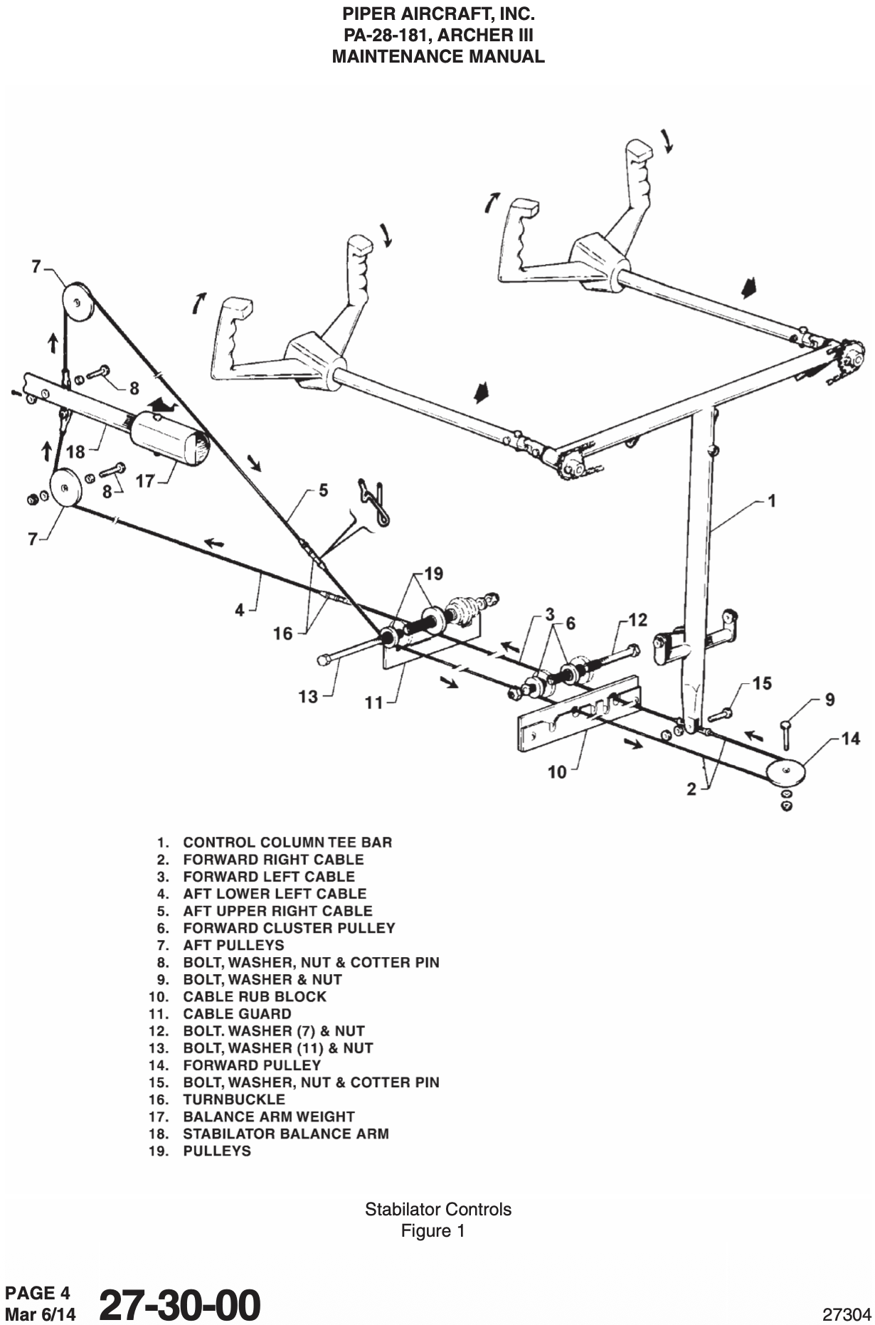
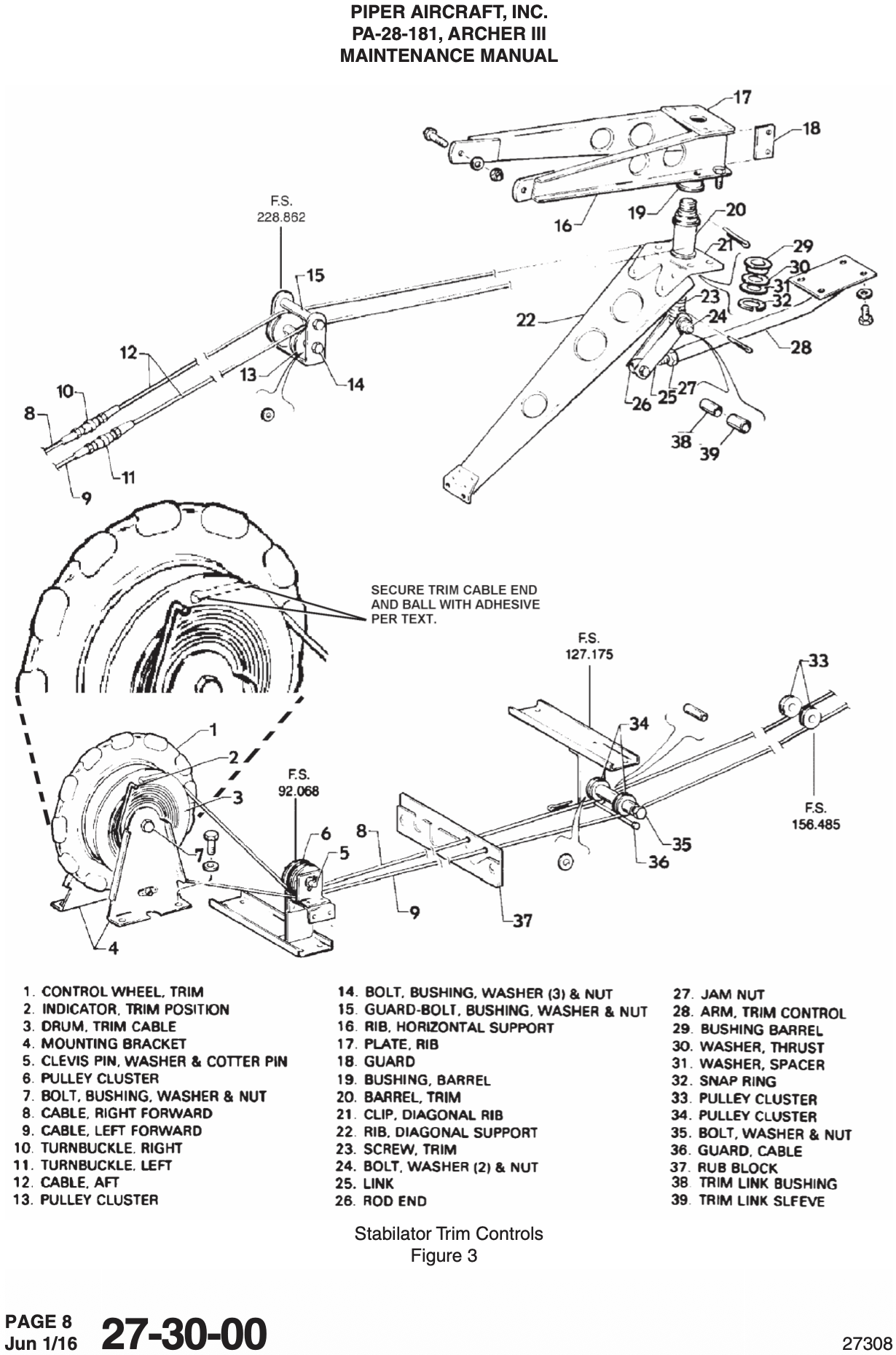
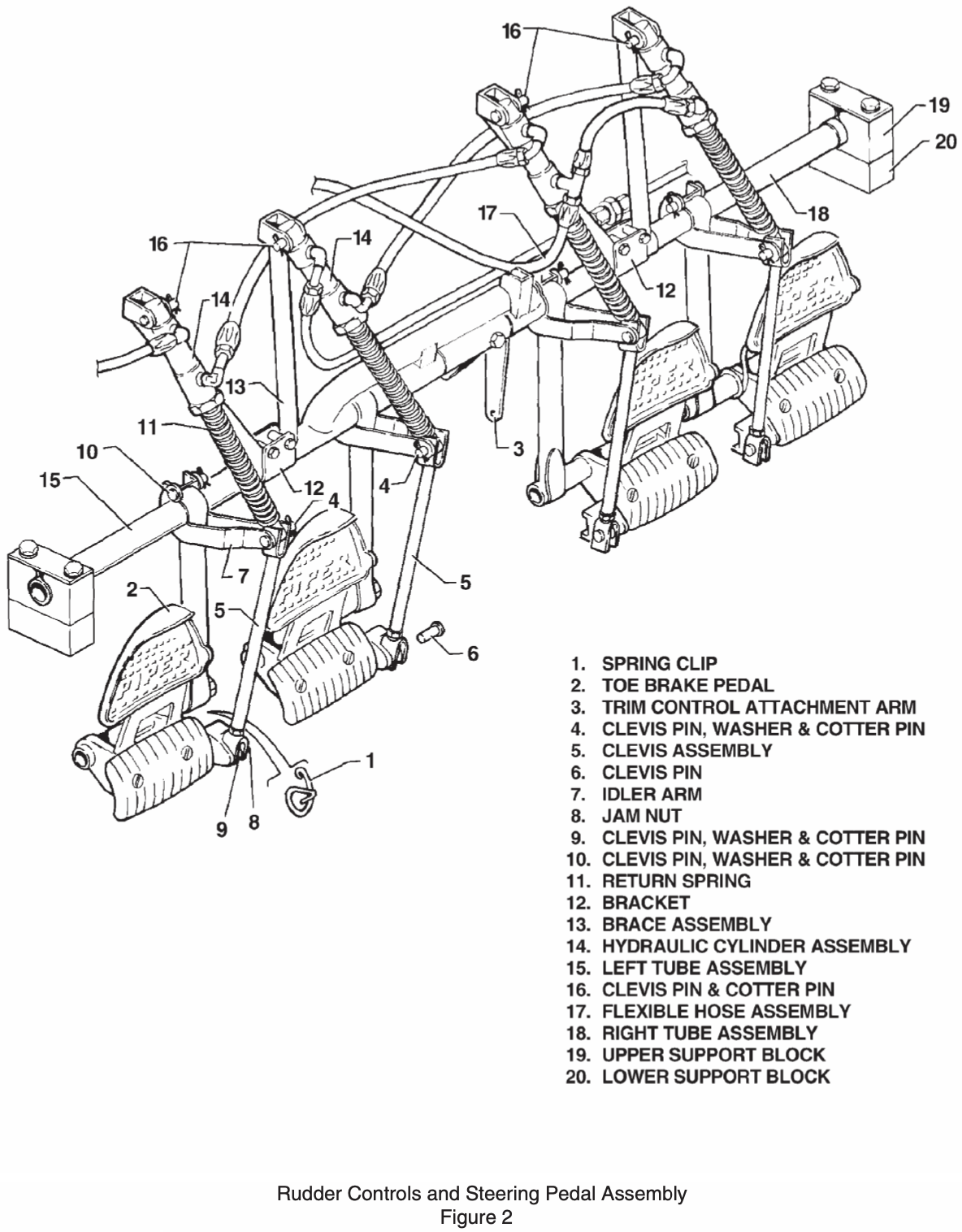
- Stabilator
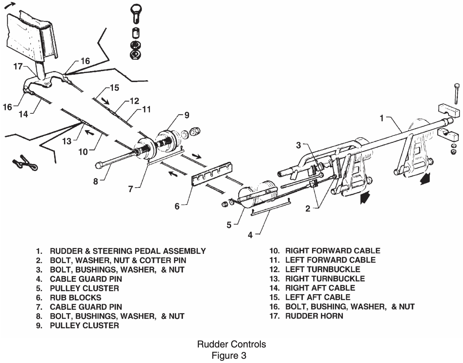
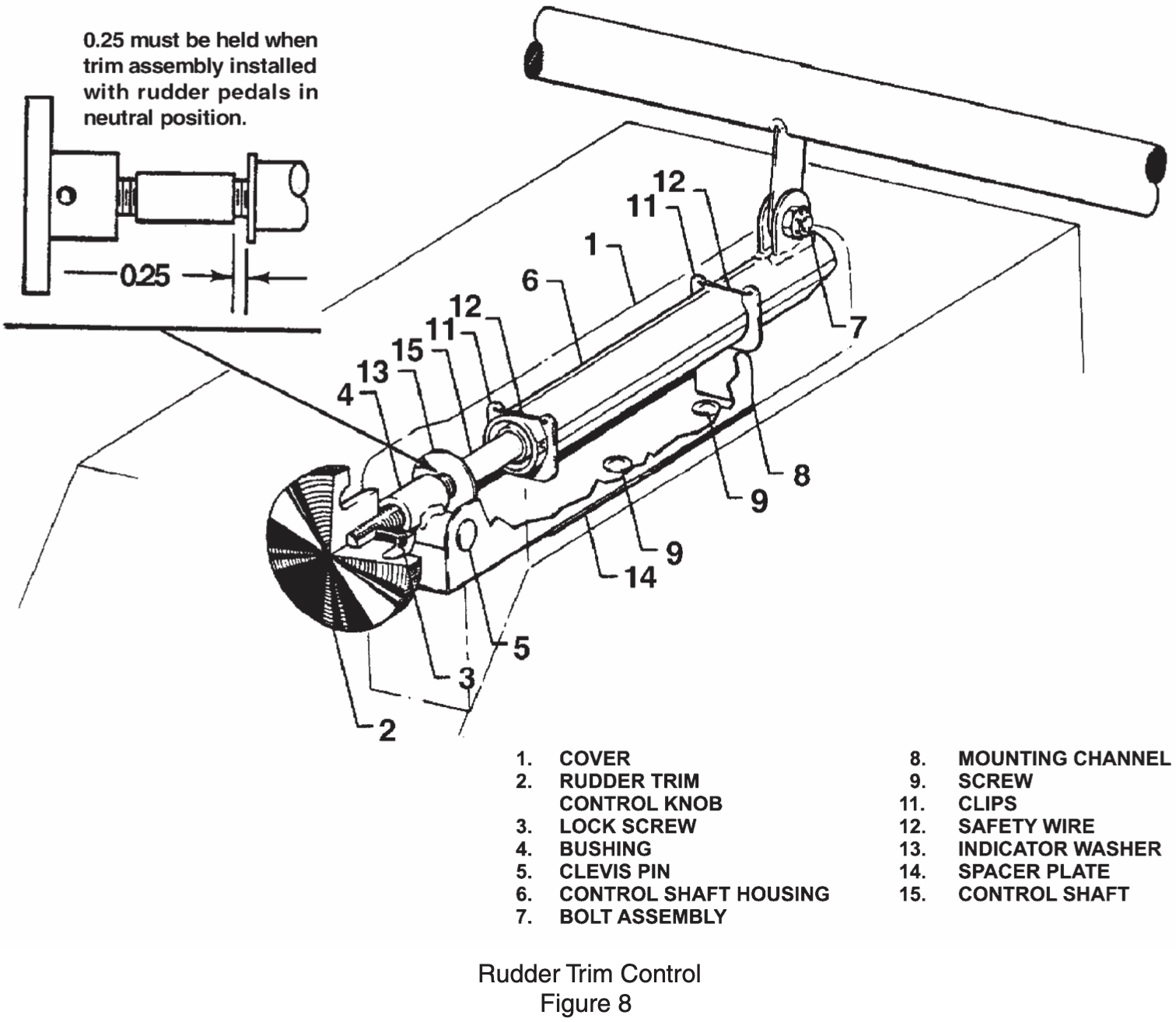
- Rudder
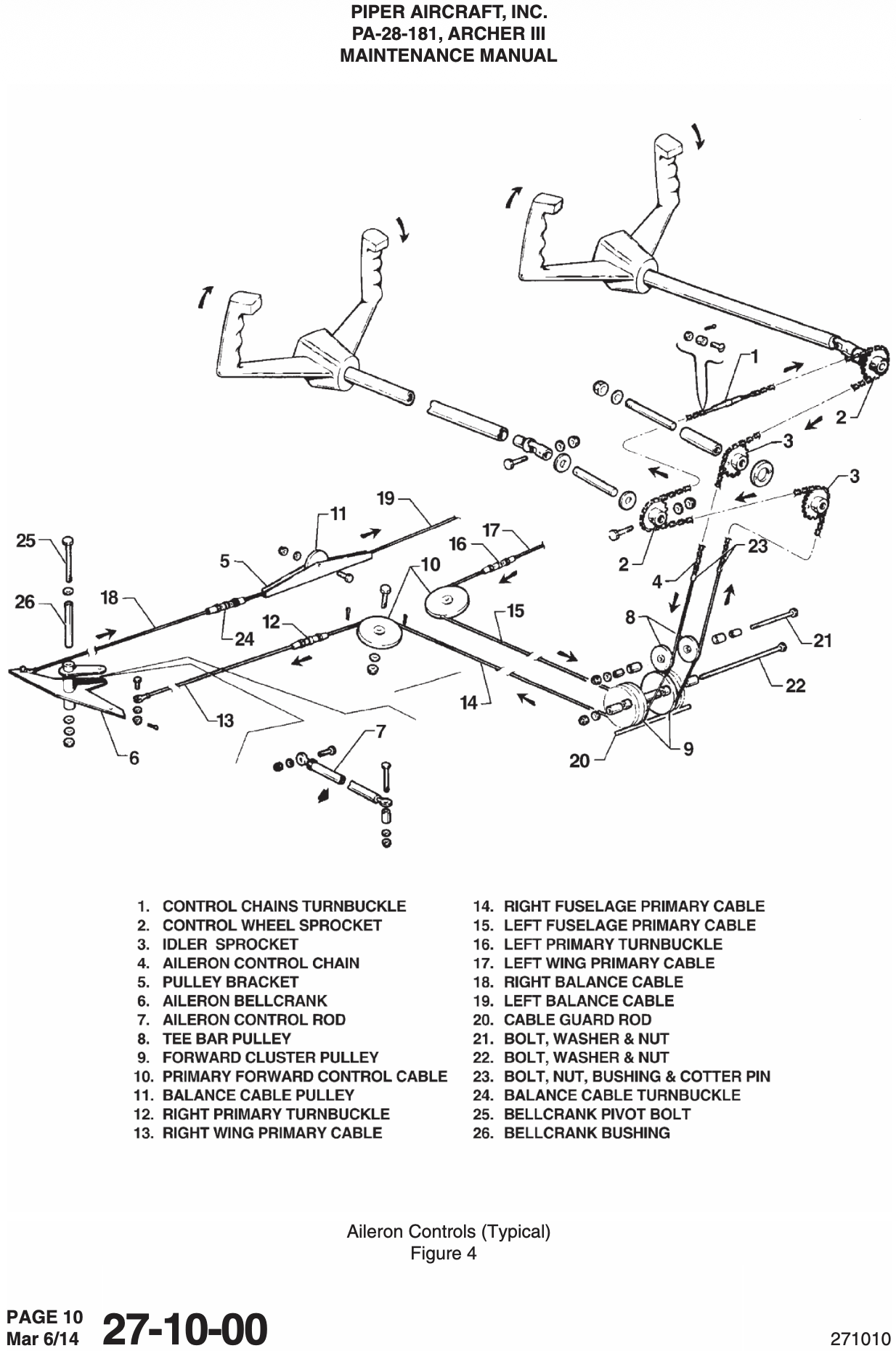
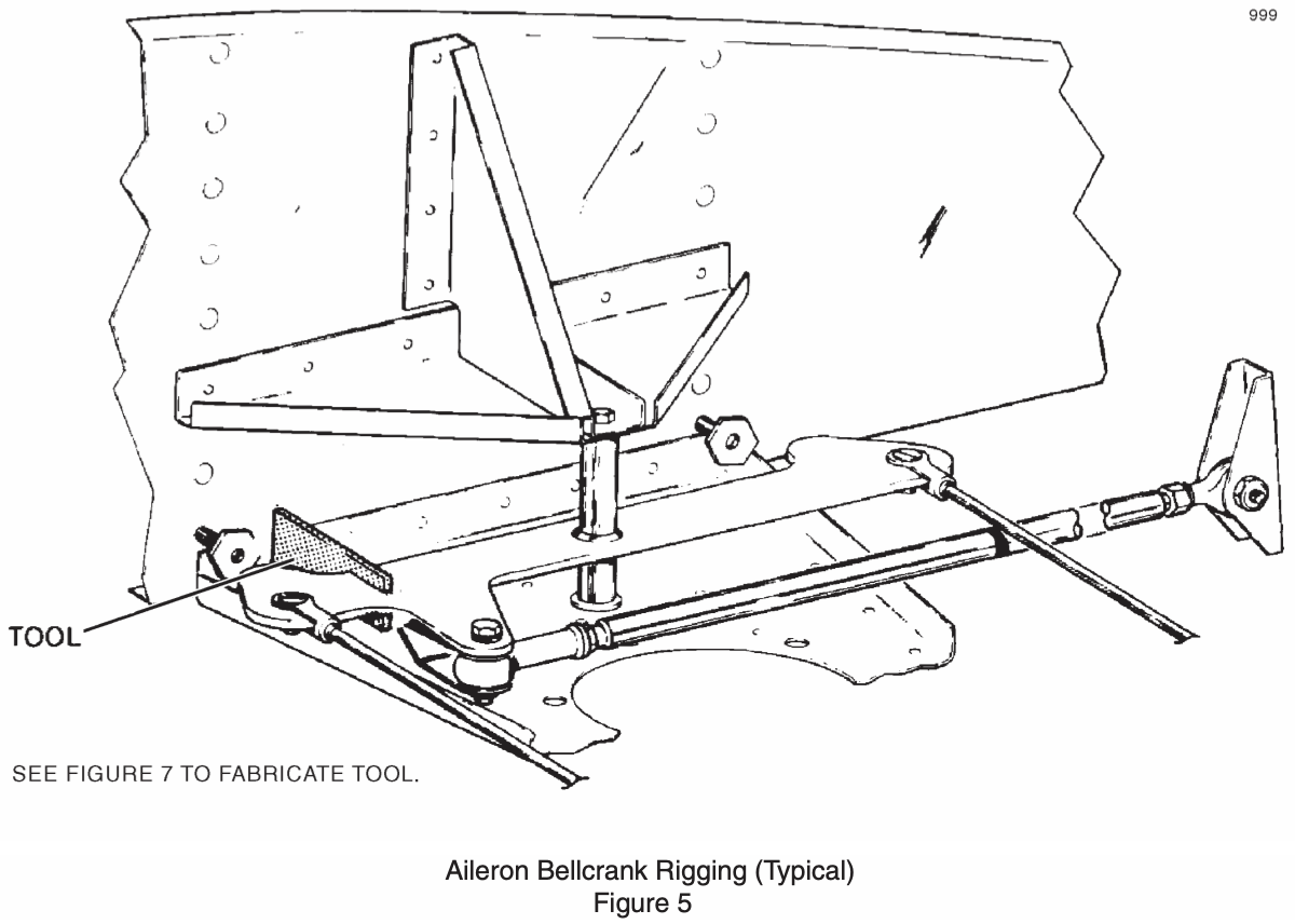
- Ailerons
- Differential
- Cables between the controls and the surfaces
- Balance weights on control surfaces prevent flutter of the control surfaces in flight
See FAA-H-8083-31B Aviation Maintenance Technician Handbook - Airframe page 4-88:
As a general rule, repair the control surface in such a manner that the weight distribution is not affected in any way, in order to preclude the occurrence of flutter of the control surface in flight. Under certain conditions, counterbalance weight is added forward of the hinge line to maintain balance. Add or remove balance weights only when necessary in accordance with the manufacturer's instructions. Flight testing must be accomplished to ensure flutter is not a problem. Failure to check and retain control surface balance within the original or maximum allowable value could result in a serious flight hazard.

Secondary Flight Controls
NOTE
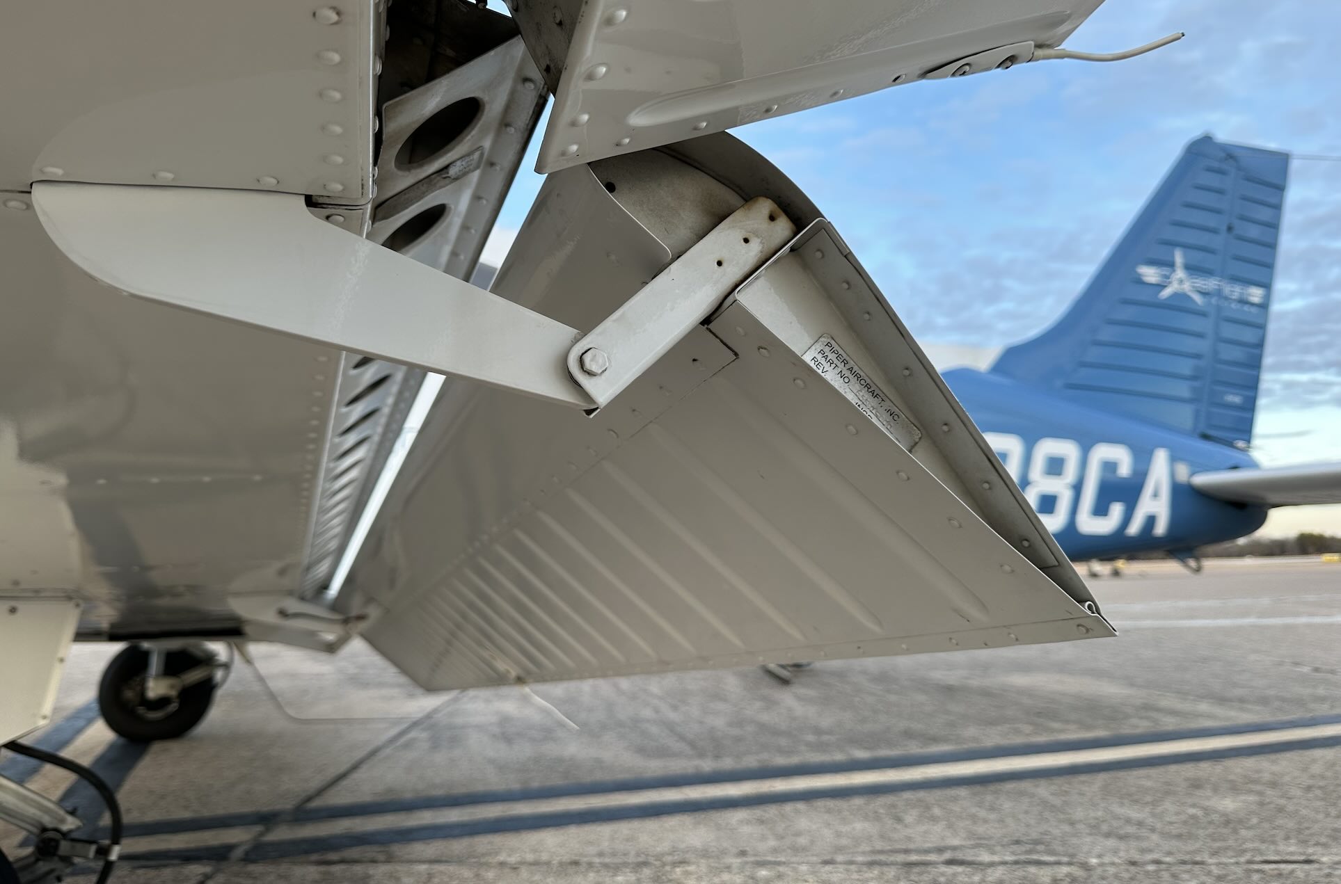
While the right flap can be used as a step while in the up position, it's generally advisable to avoid doing so if it is safe to prevent damaging the attachment bracket, which can break from the weight of a person.
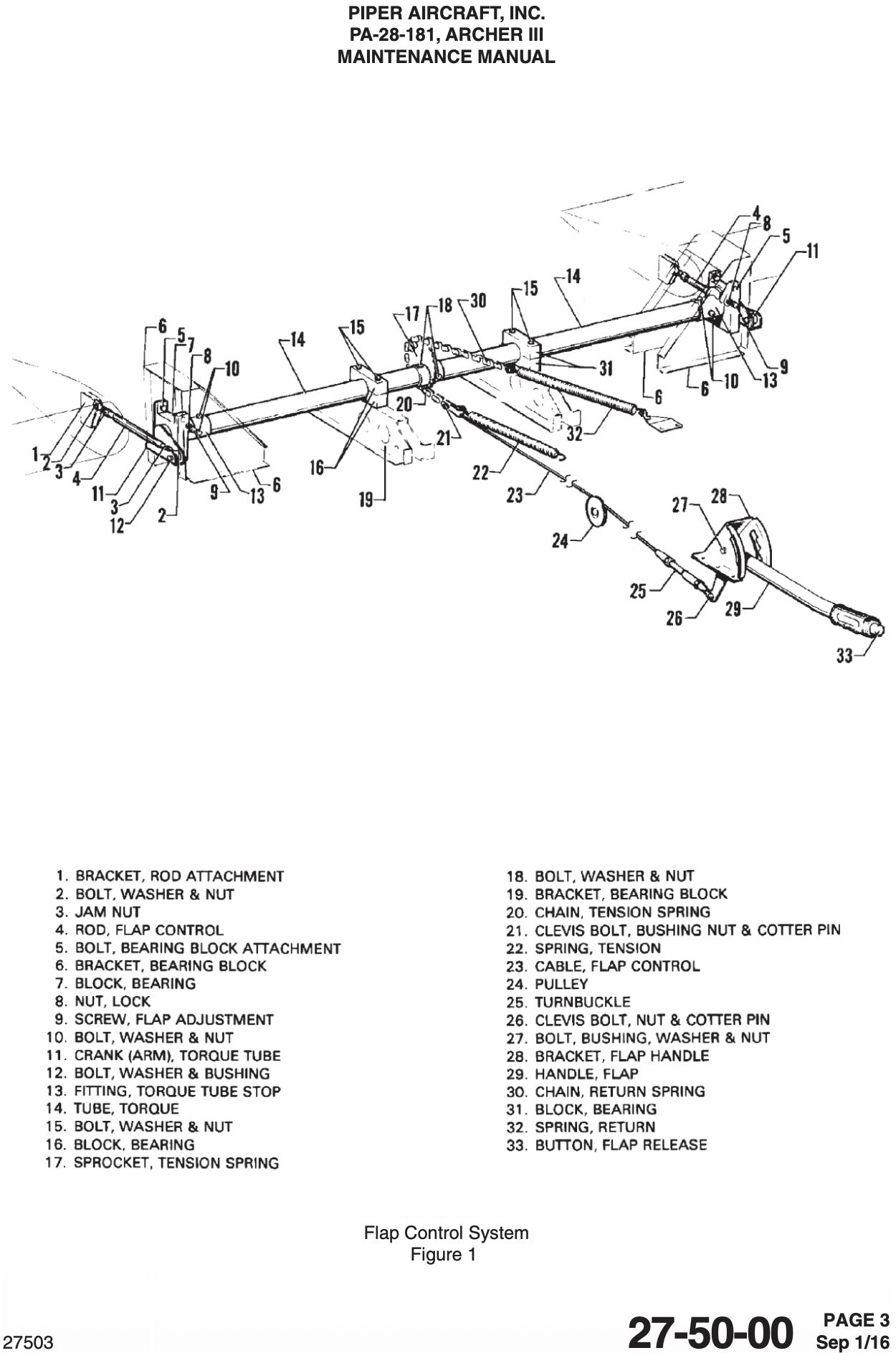
Flaps
Slotted type
Mechanically actuated with spring to return to up position
See POH (VB-2749) page 7-5:
A past-center lock incorporated in the actuating linkage holds the flap when it is in the up position so that it may be used as a step on the right side. The flap will only support a step load in the full up position.
Trim
- Stabilator
- Rudder
- Rudder trim uses a screw and spring mechanism to apply rudder pressure.
Stabilator trim is an anti-servo tab, moving in the same direction as the stabilator to increase control pressure
Powerplant
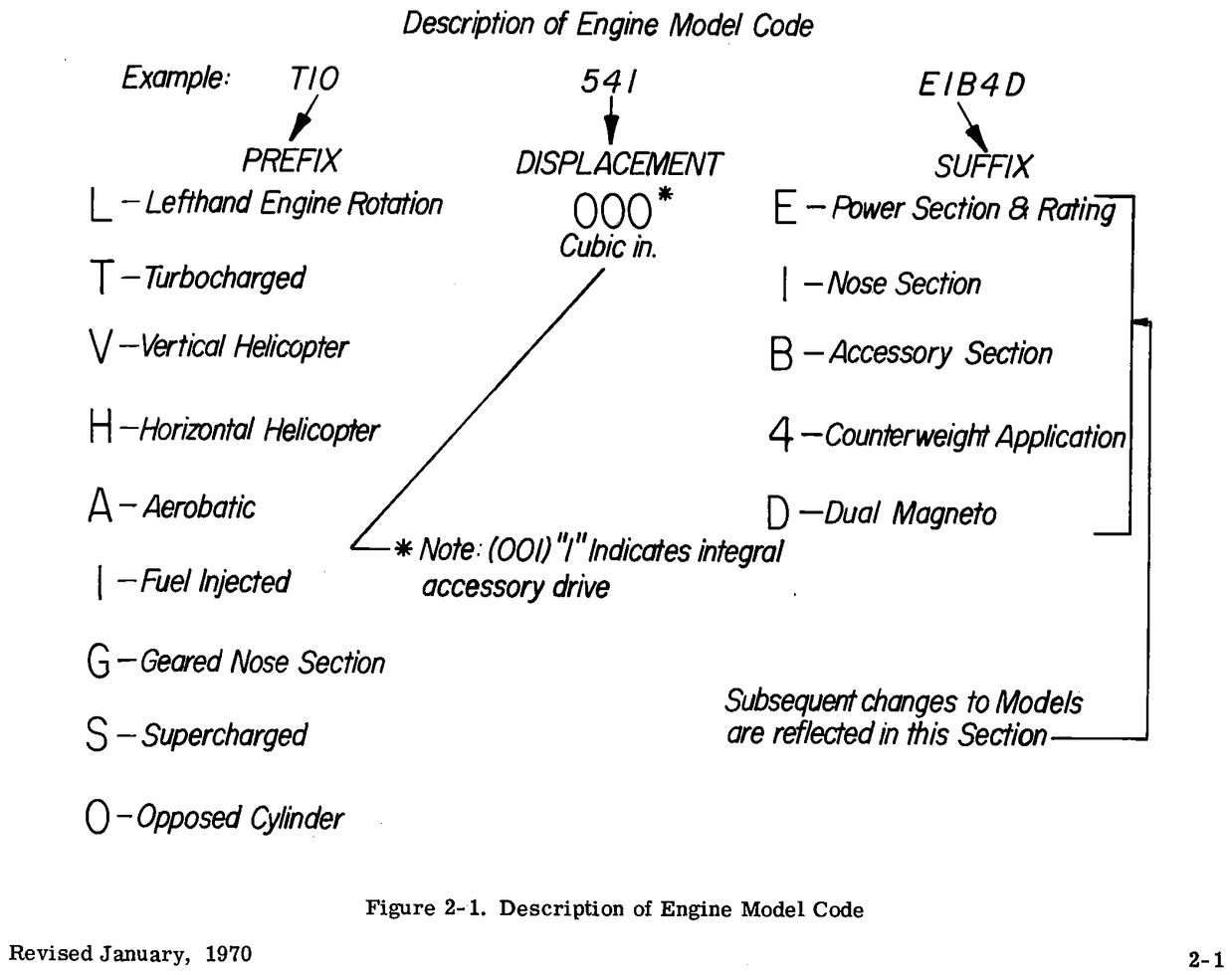
- L4HAND
- Lycoming IO-360-B4A
- I - fuel injected
- O - opposed cylinders
- 360 cubic inch displacement
- 4 cylinder
- Horizontally opposed
- Air-cooled
- Naturally aspirated
- Direct-drive
- Lycoming IO-360-B4A
- Takeoff power: 180 HP @ 2700 RPM
- Fuel injected
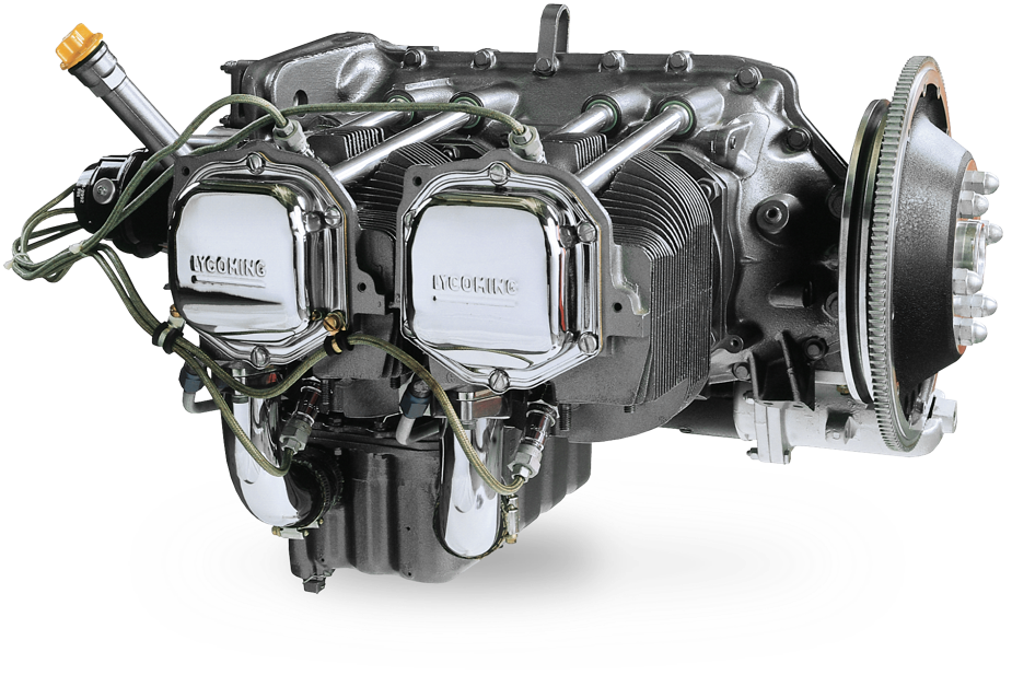
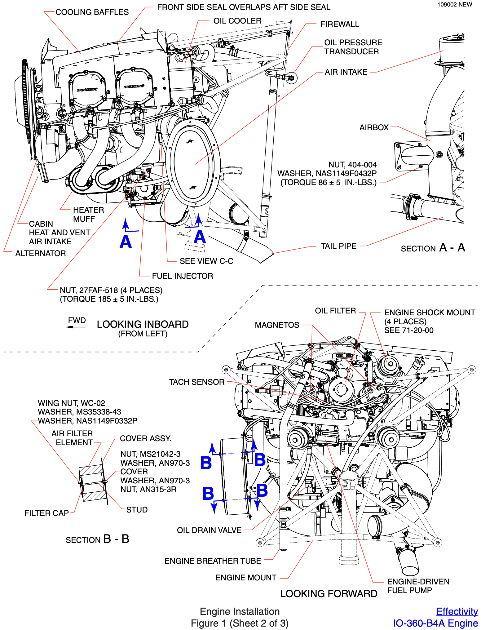
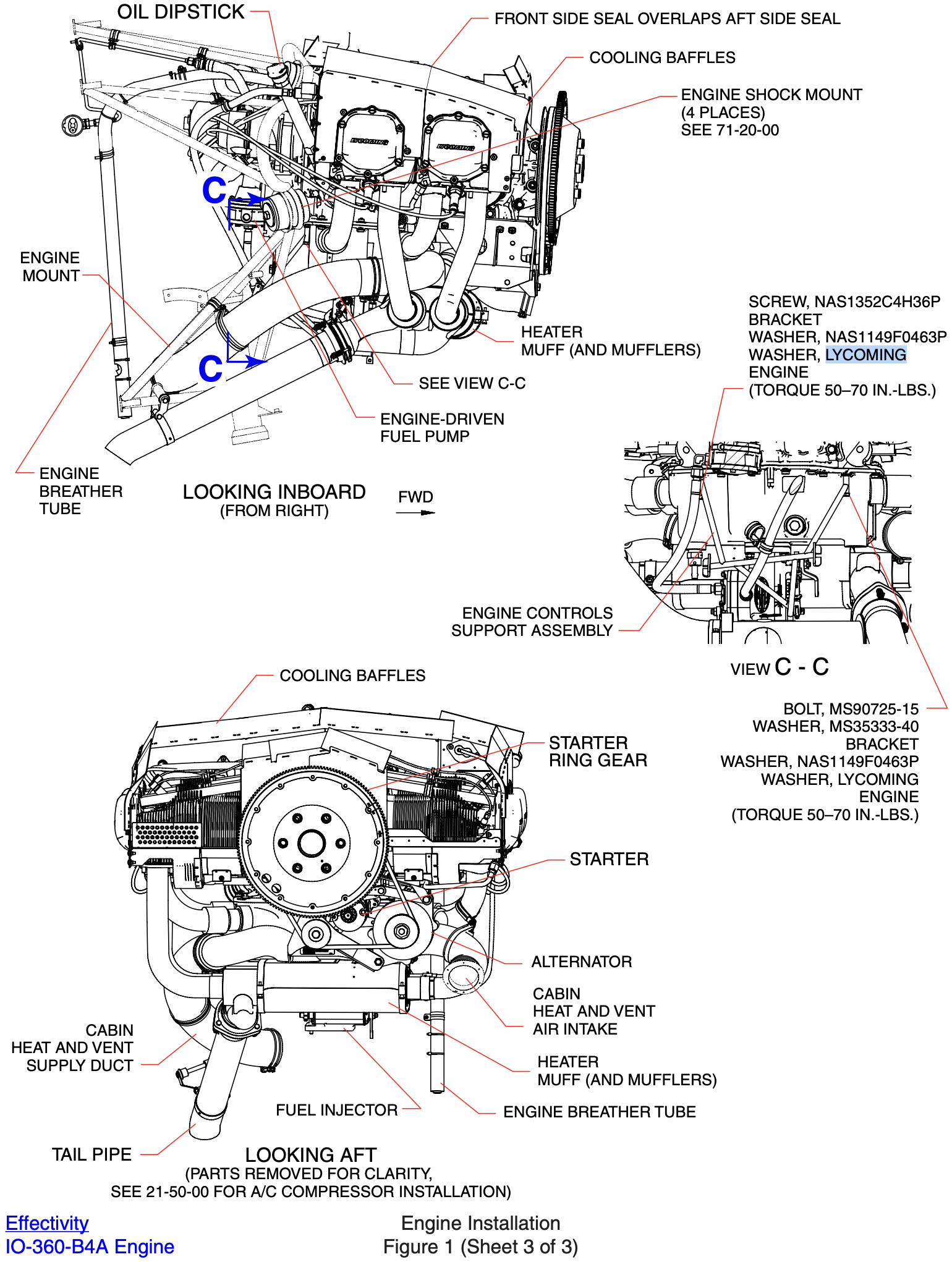
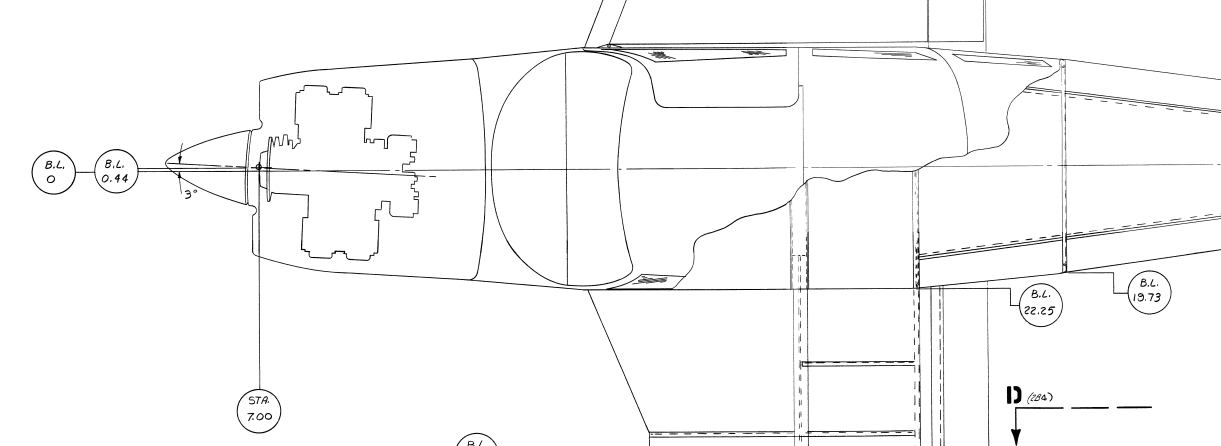
Engine Orientation
The image below is the only publically available document that I have been able to find that indicates the engine orientation in the Piper Archer.
The following images are not publically available, but are screenshots provided by Piper from their General Arrangement Drawing better showing the orientation of the engine in the plane.
Cooling System
- Air cooled
- Air flows into the inlets behind the prop, over the engine, and exits out the bottom
- Circulating oil (along with the oil cooler) aids in cooling
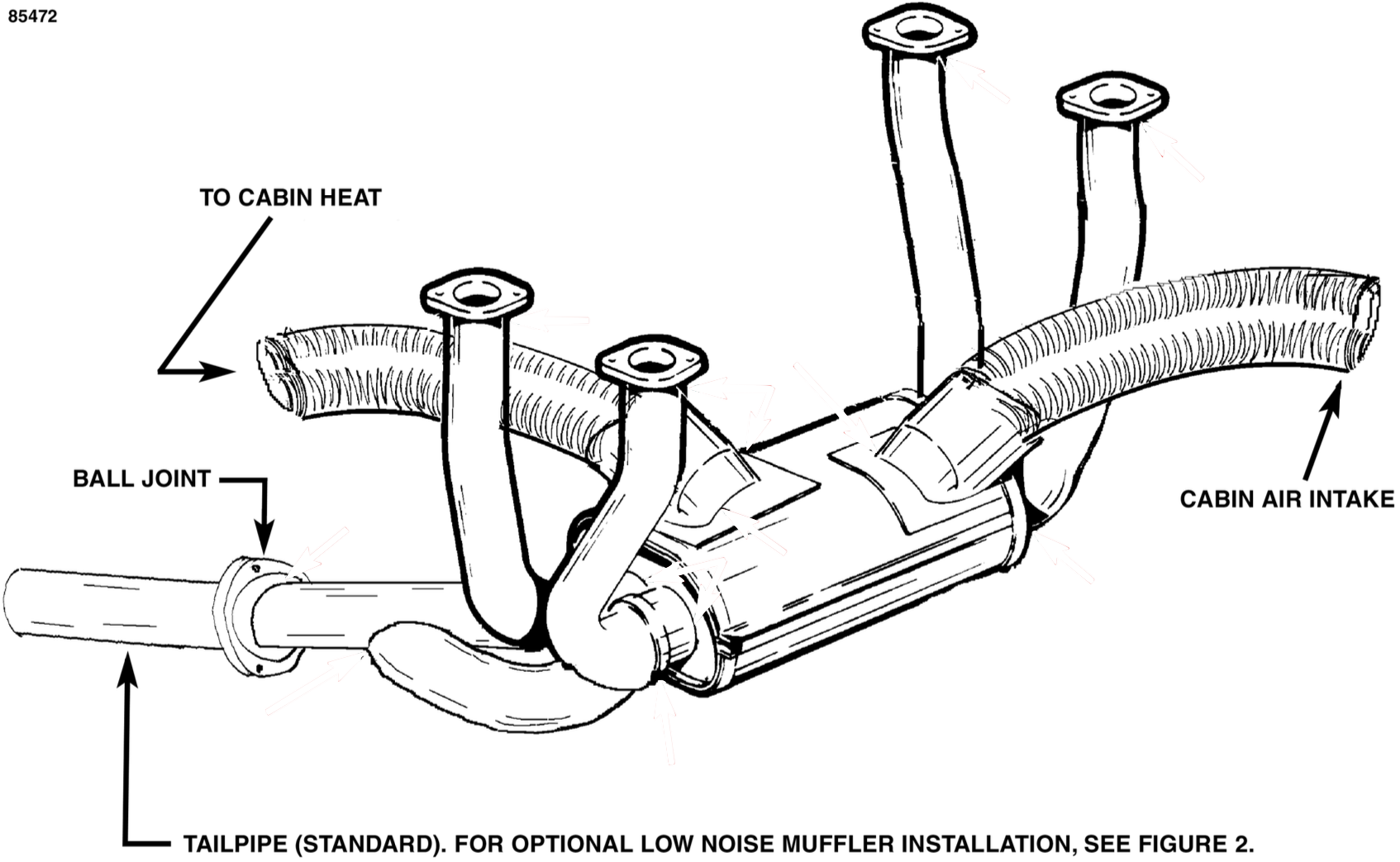
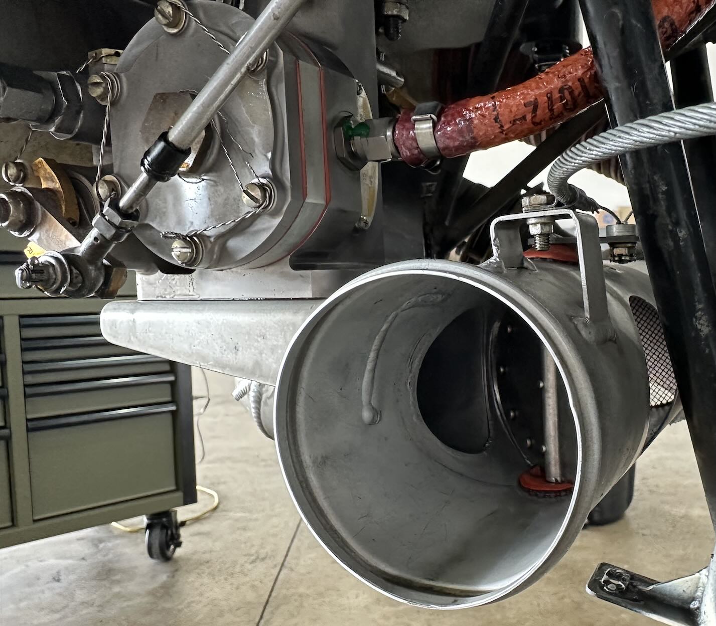
Exhaust System
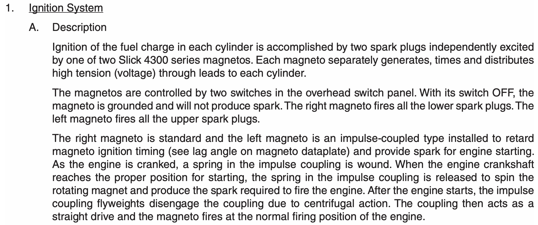
Ignition System
Archer Airplane Maintenance Manual (PN 761-883) 71-00-00 page 2:
The ARCHER III is equipped with two Slick 4373 magnetos. These magnetos are engineered to give trouble free ignition, are completely self contained, and have an impulse coupling to aid in starting.
Induction System
- Note as described in the Fuel System section below that fuel is injected into the cylinder head intake ports.
Propeller
- 2-bladed
- Fixed-pitch
- Sensenich
- Model 76EM8S14-0-62
- Aluminum
- 76 inch diameter
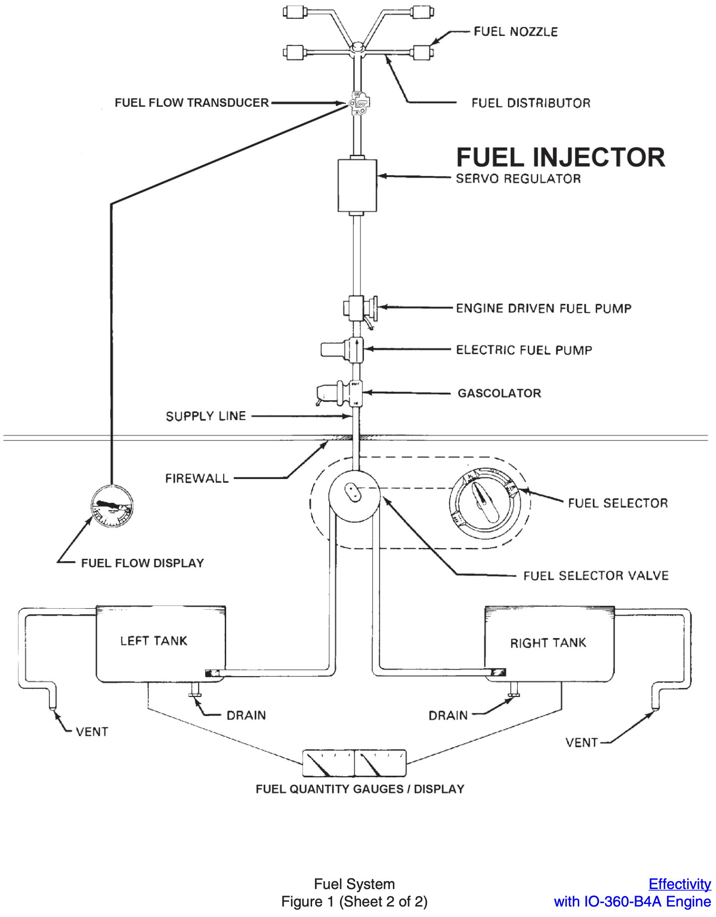
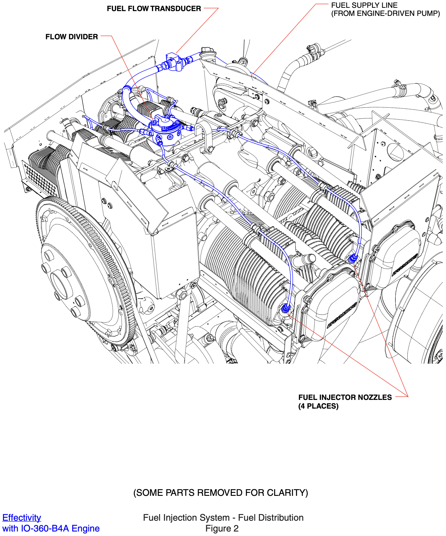
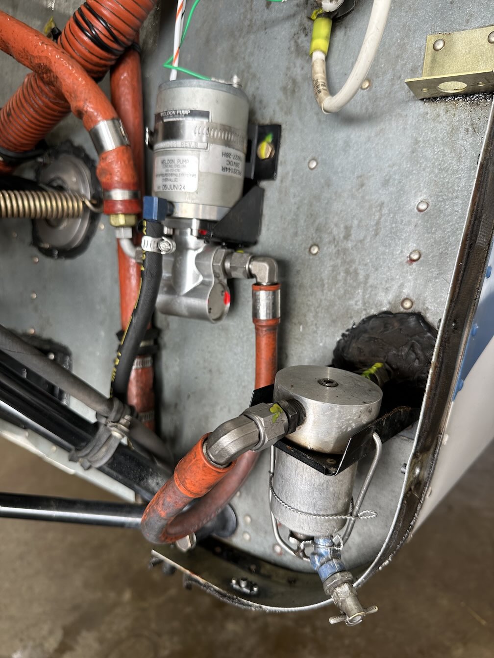
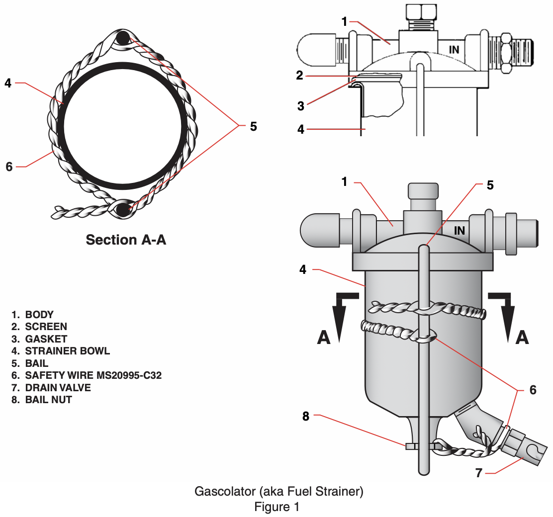
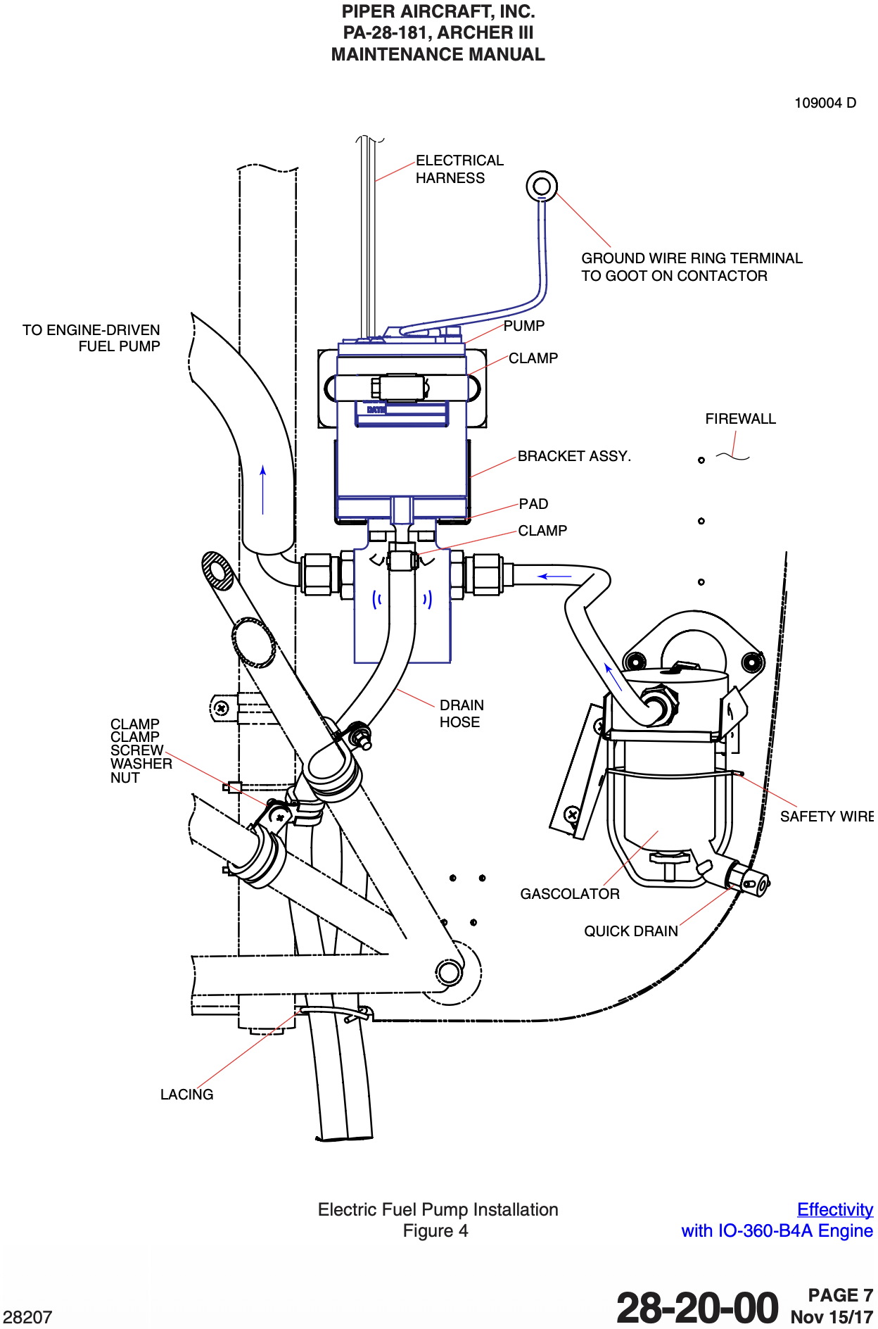
Fuel System
50 gallons total capacity
48 gallons usable
- 24 gallons usable per side
Engine driven and electric fuel pump
Archer Airplane Maintenance Manual (PN 761-883) 71-00-00 page 1:
The fuel injection system is a conventional, Bendix-type RSA5 system, consisting of a fuel injection servo that meters fuel delivery based on engine intake airflow, a flow divider that evenly distributes fuel to the 4 cylinders and injection nozzles that direct vaporized fuel into the cylinder head intake ports. An alternate air control is provided in the event of blockage of the primary, filtered airflow path to the engine. The design of the system will also continue to provide the required, minimum heat rise to prevent or eliminate icing of the system by pulling airflow from around the exhaust tailpipe.
Oil System
- Wet sump
- Capacity: 8 quarts
- Minimum safe quantity: 2 quarts
Electrical
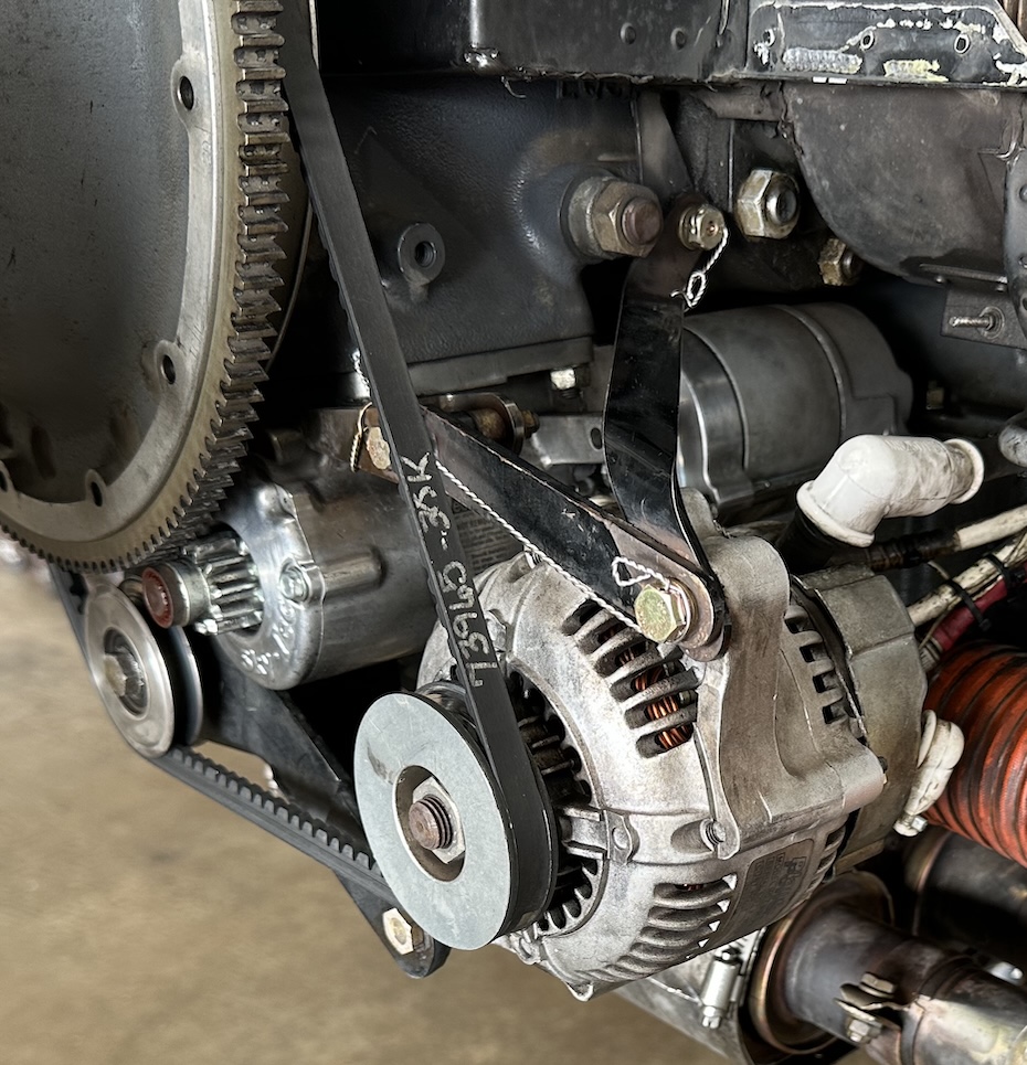
70 ampere alternator
28 volt electrical system
24 volt primary battery
Single external power connector
Isolated 24 volt emergency battery
POH Page 7-49:
When energized by the battery master switch the primary battery supplies electrical power to the starter, as well as all items on the Essential Bus, Non-Essential Bus and Lighting Bus.
The emergency battery provides electrical power to the emergency bus in the unlikely event of a complete electrical failure. With the EMERG BATT switch in the ARM position, power is applied to the emergency bus automatically if electrical power is removed from the primary electrical system. Functions available via the emergency bus include all standby instrument functions, PFD functions (nav/com #1 only), and the audio panel. The emergency battery is sized to provide a minimum duration of 30 minutes of electrical power to the emergency bus equipment.
ALTR AMPS- Positive means the alternator is providing current to the system
- This is expected and normal while the engine is running
BATT AMPS- Negative means the battery is providing current to the system
- This is normal when the electrical system is on but the engine is not running
- This is abnormal when the engine is running as it indicates the battery is discharging
Archer Airplane Maintenance Manual (PN 761-883) 71-00-00 page 2:
In addition to the previously mentioned components, each ARCHER III engine is furnished with a starter, 70 ampere alternator, 28 volt electrical system, shielded ignition, and fuel pump.
Voltage regulator see POH (VB-2749) page 7-49:
A solid state voltage regulator is located just forward of the instrument panel on the left side of the aircraft. The voltage regulator is designed to regulate the electrical system bus voltage to 28 volts and to prevent damage to the electrical and avionics equipment by removing the alternator from the circuit if its output exceeds 32 volts. In this situation an ALTR FAIL warning CAS message will illuminate.
Hydraulic System
Piper Archer has a separate master cylinder for the handbrake, see POH (VB-2749) page 7-7:
The toe and hand brakes have their own master brake cylinders, but they share a common reservoir.
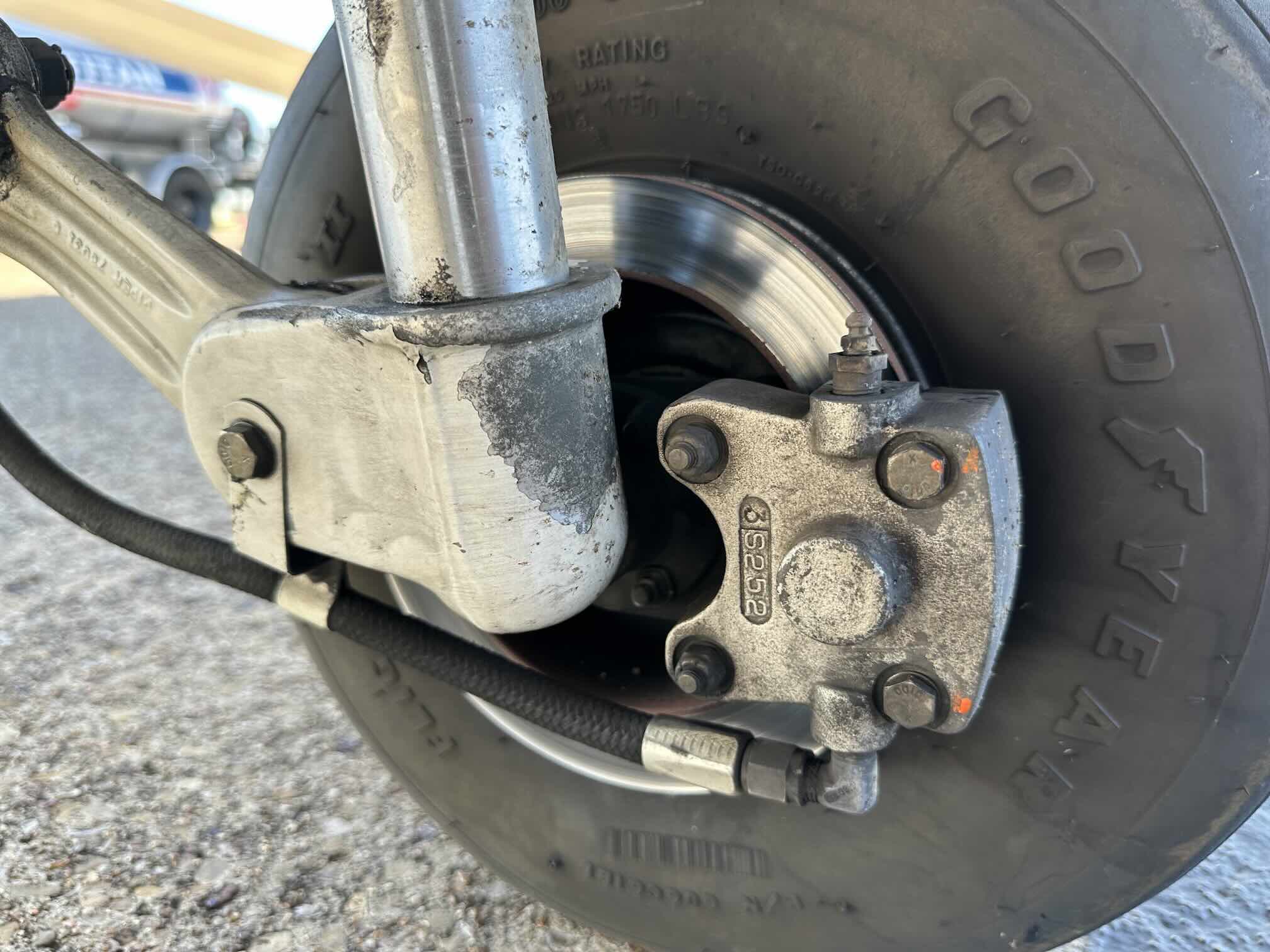
Landing Gear
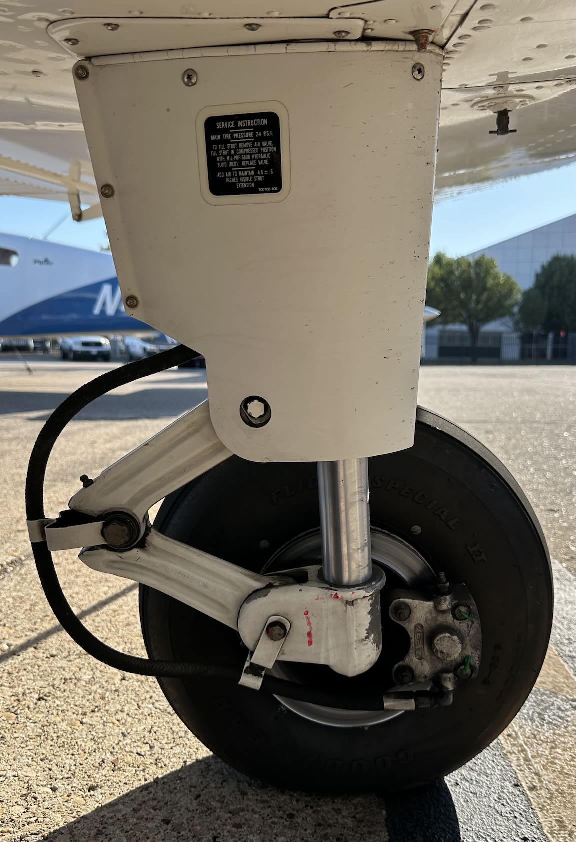
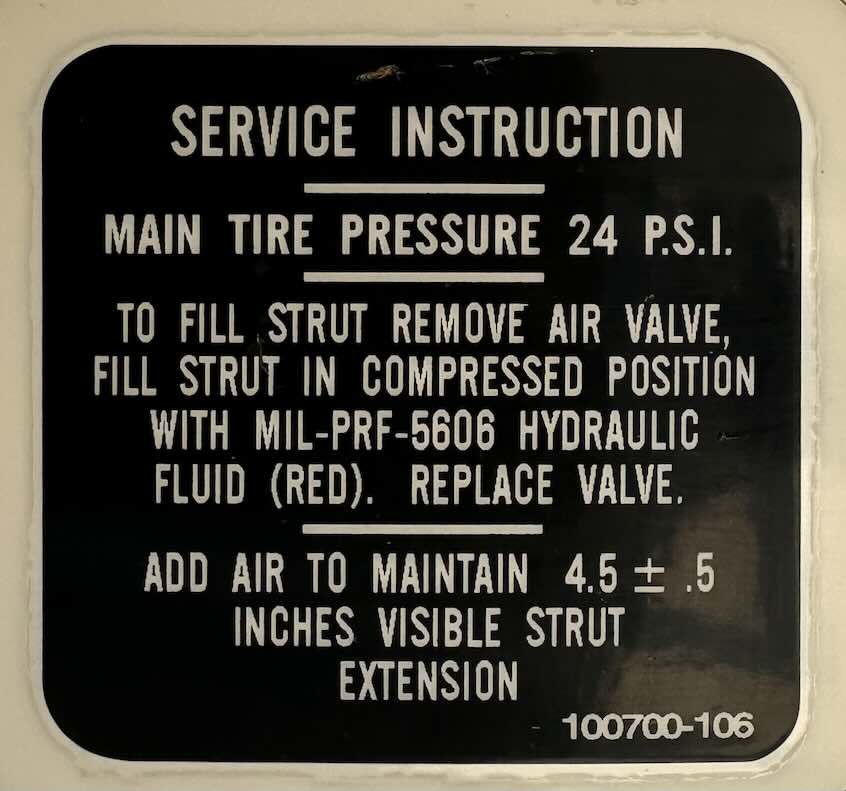
- Fixed tricycle gear
- Oleo struts
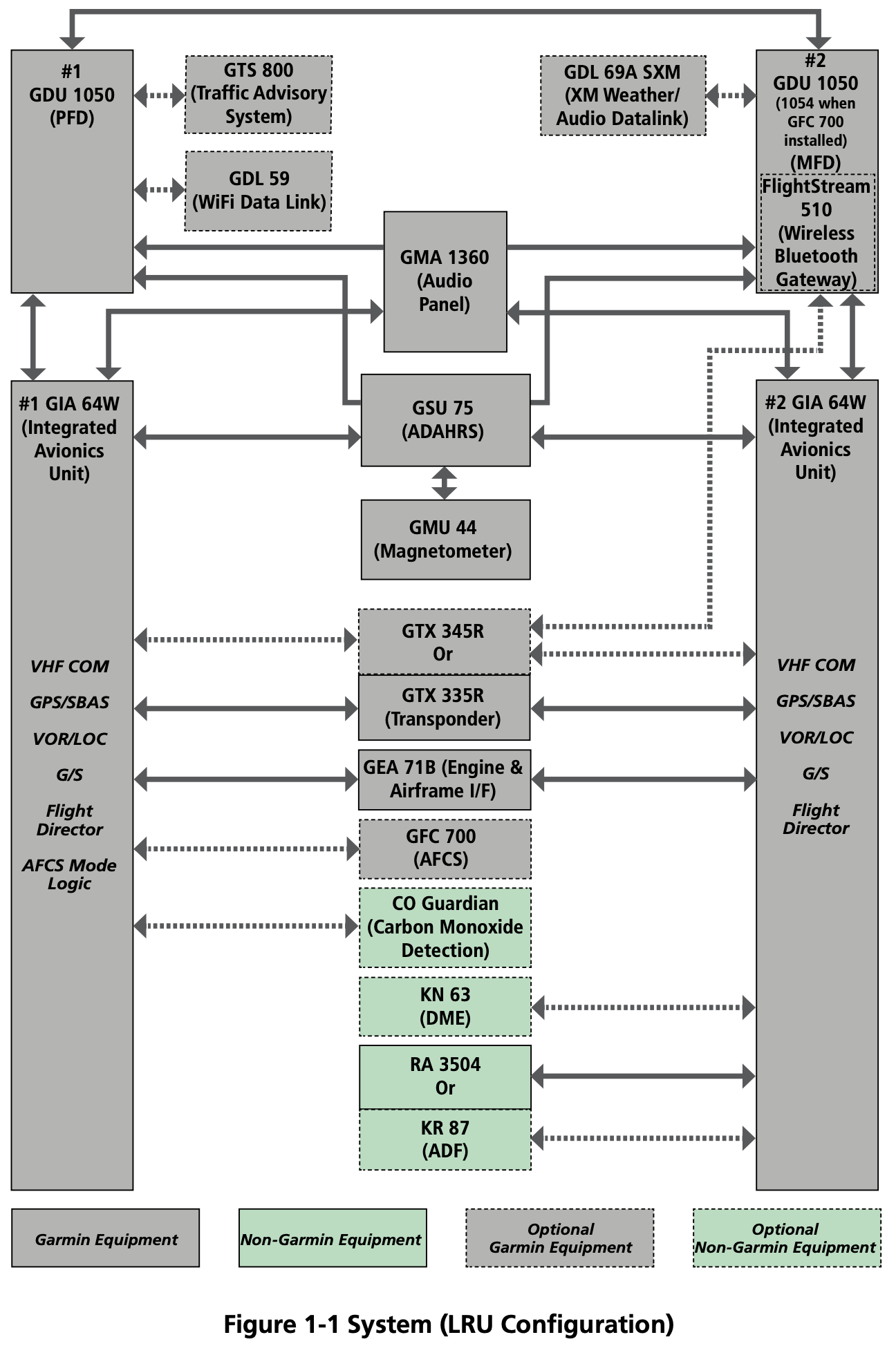
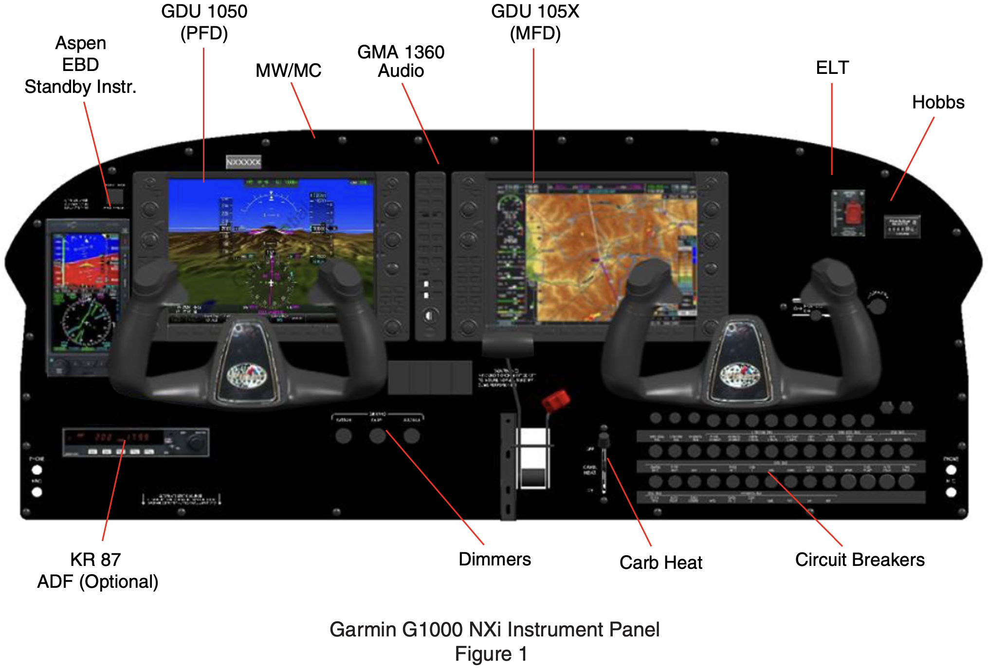
Avionics
Primary
- Garmin G1000 system
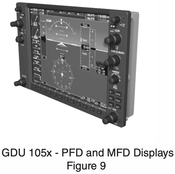
- GDU 1050
- PFD and MFD screens
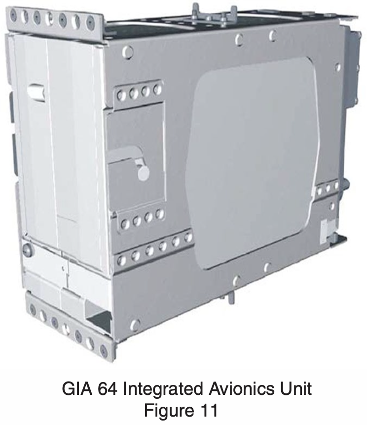
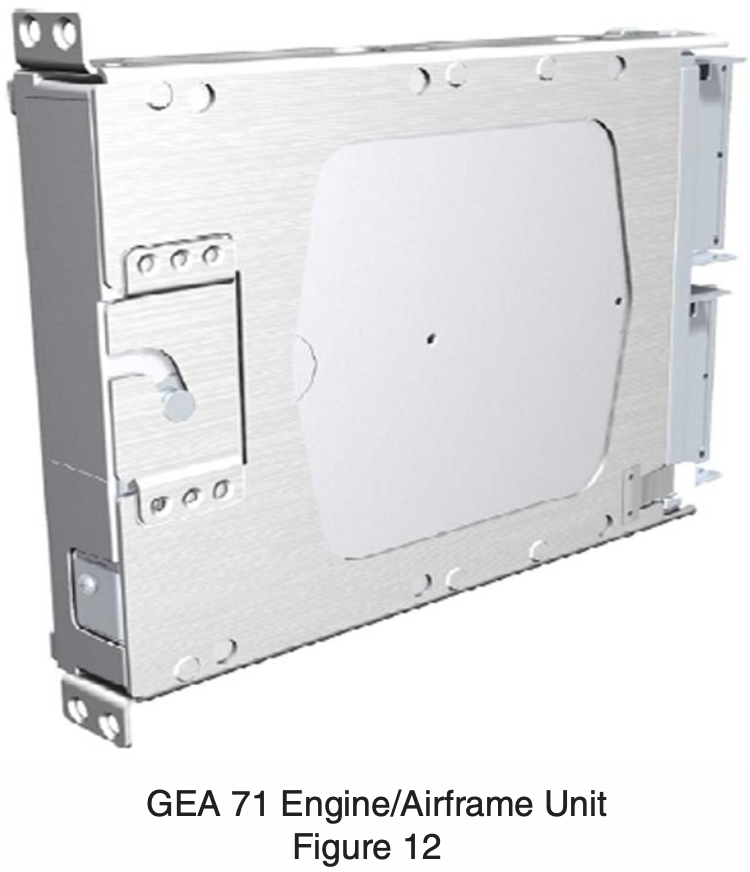
- GIA 64 Integrated Avionics Unit (IAU)
- VHF COM/ NAV receivers
- WAAS GPS receiver
- Flight Director
- Processor
- Communication interface
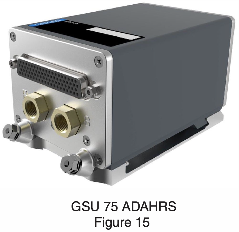
- GSU 75 ADAHRS
- Located on left rear side of fuselage
- GMU 44 Magnetometer
- Located on the underside of the left wing
- GDU 1050

Backup
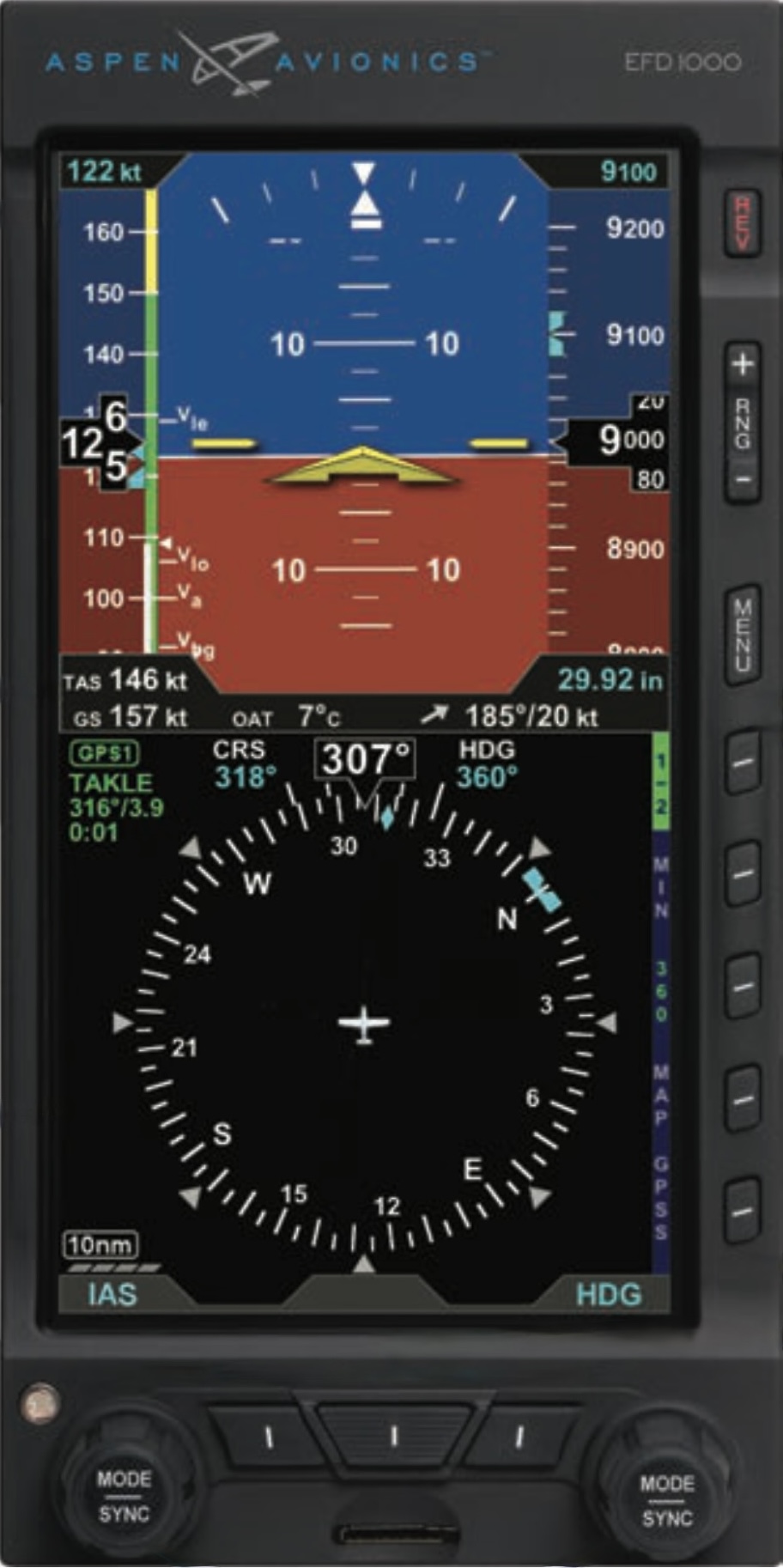
Aspen Avionics Evolution Backup Display (EBD) provides backup attitude, heading, altitude, airspeed, and VSI
The POH (VB-2749) page 2-15 states that the Evolution Backup Display Pilot's Guide (091-00027-001) is the correct supplement for the EBD
Archer Airplane Maintenance Manual (PN 761-883) 34-24-00 page 1:
The Aspen Avionics Evolution Backup Display (EBD) system provides a standby display for the primary IFDS system. The EBD contains an internal ADAHRS that is used to provide attitude and heading data for the display. The EBD as installed by Piper is connected to the emergency power buss and is powered by the emergencey battery to provide a minimum of 30 minute operation in the event of power loss under all foreseeable operating conditions. In addition, the EBD contains an internal battery which will provide an additional nominal 30 minute operation in the event emergency battery exhaustion.
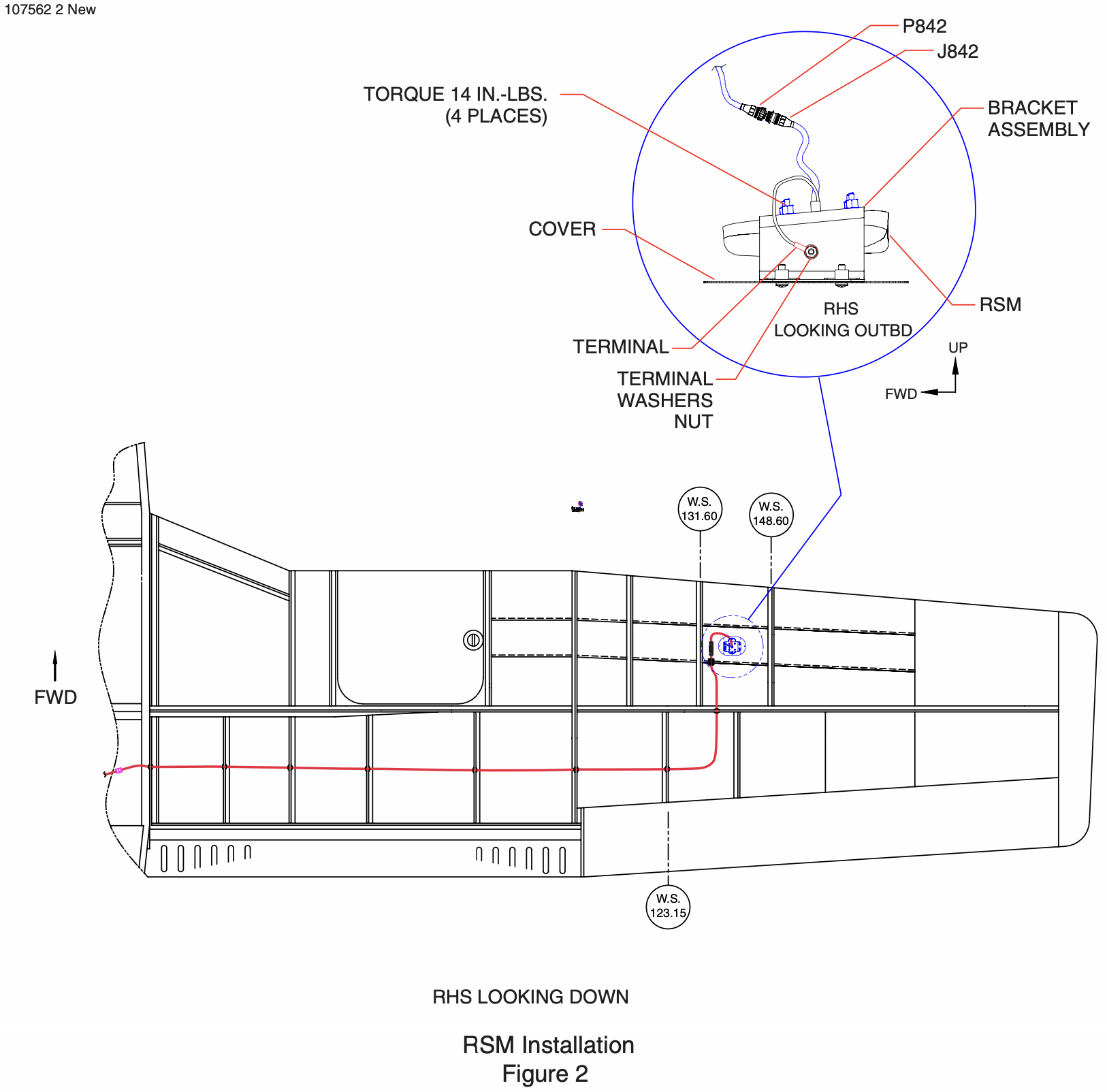
Remote Sensor Module (RSM)
- Located on the underside of the right wing
The RSM contains the following sub-systems:
- 3D magnetic flux (heading) sensors
- Outside Air Temperature (OAT) sensor
- Emergency backup GPS engine and antenna
Archer Airplane Maintenance Manual (PN 761-883) 34-24-00 page 10:
The RSM is installed internally on an access cover on the underside of the aircraft right wing.
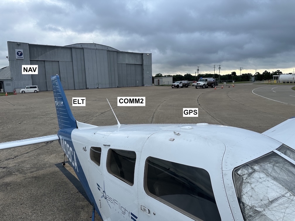
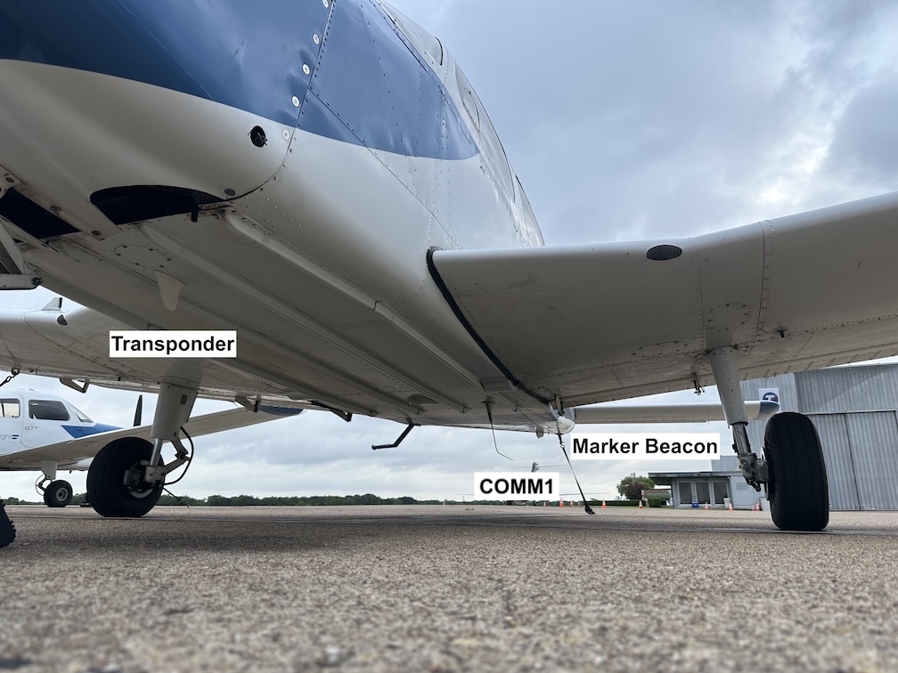
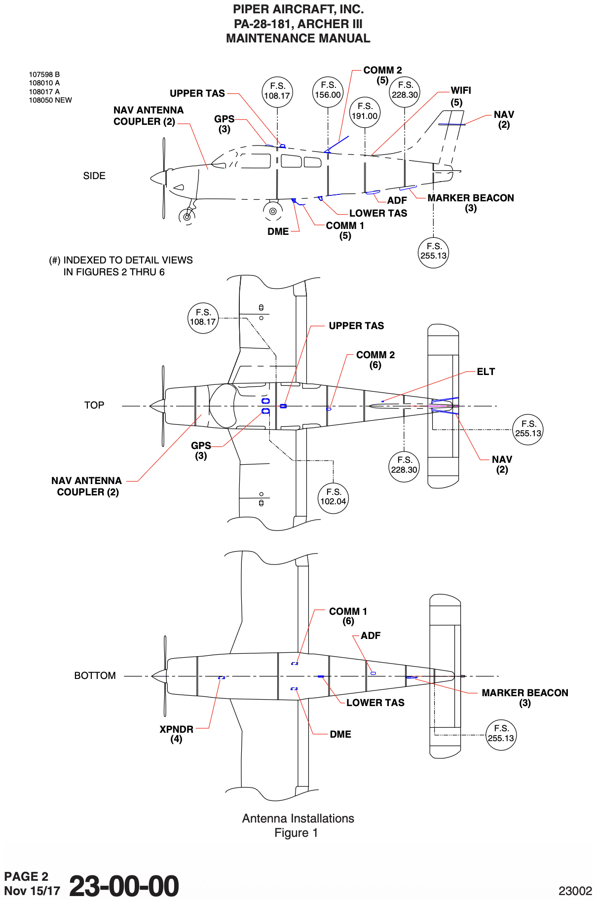
Antennas
- ADS-B shares the transponder antenna.
Pitot-static / Vacuum System

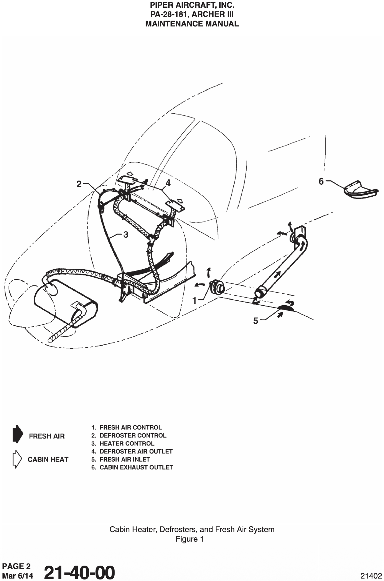
Environmental
Deicing and Anti-icing
- TBD
Appendix